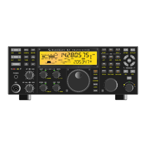
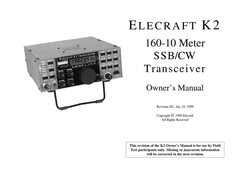
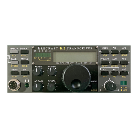
ELECRAFT K2 User manual

Alignment Instructions
Extracted from the K2 Manual
By Don Wilhelm W3FPR

Setting the AGC Threshold Exit the CAL S HI function by tapping MENU.
Make sure the RF GAIN control is rotated fully clockwise.
Locate potentiometer R1 on the Control board (right side, as
viewed from the front of the K2).
Set your DMM for DC volts. Connect the (-) lead of the
DMM to one of the ground jumpers or to the K2 chassis ground.
Touch the (+) lead to pin 5 of U2 on the Control board. (U2 is
located just above trimmer R1. Pin 5 is the pin nearest diode
D1.)
Adjust R1 for a reading of 3.80 volts on the DMM. This is the
suggested setting, but it can be adjusted later to suite the
operator.
i The S-meter must be realigned anytime
the AGC
threshold setting is changed. S-meter
alignment is covered
in the following steps:
S-Meter Alignment
Using the menu, select the CAL S LO function (S-meter
zero). Hold MENU a second time to activate it.
Turn the VFO knob until you see only the left-most segment
of the LED bargraph lit. Then turn the knob a bit more clockwise
until this LED just turns off.
Exit the CAL S LO function by tapping MENU. Enter the
menu again and select CAL S HI (S-meter full-scale
sensitivity).
Turn the RF GAIN fully counter-clockwise (minimum gain).
Adjust the VFO knob until you see segment 9 of the bar graph
lit,
then turn it a bit more counter-clockwise until segment 10 just
turns on (right-most segment).
Turn the RF GAIN control back to its full clockwise position.
1

4 MHz Oscillator Calibration PLL Reference Oscillator Range
Test
Plug the frequency counter probe into P6 (Control board).
Connect the probe tip to the PLL reference oscillator test Set up the K2 internal counter as described for 4 MHz
point, TP3 (left-front corner of the RF board, near U4). Oscillator Calibration (at left, first three steps).
Using the menu, select CAL FCTR , then hold
MENU a second time to enable the frequency counter. The
counter
If you have an external frequency counter probe connected to
TP3 along with the K2's internal counter probe, disconnect it.
should show a frequency of 12090 kHz +/- 30 kHz. If it is
0000.00,
When you’re in frequency counter mode, the BAND + and
changing rapidly, or out of range, you could have a problem with BAND - switches can be used to check the range of the PLL
the counter probe or the PLL Reference Oscillator. reference oscillator. First, tap BAND + and write down the
frequency
Use one of the following methods to adjust C22 on the
Control board (listed in order of preference): reading below (typically about 12100 kHz). Then tap BAND -
and
Connect a calibrated external frequency counter probe to
TP3,
write down this frequency reading (typically 12080-12090 kHz).
without removing the K2's internal counter probe. Adjust
C22
Ref. High Freq. Ref. Low Freq. Range (kHz)
____________ ____________ __________
until the K2's reading matches the external counter's reading.
Subtract the lower frequency reading from the higher reading.
Alternatively, you can use a calibrated short-wave or ham-
band
The range must be between 9.8 and 13 kHz (if not, see
Troubleshooting). Tap M E N U to exit CAL FCTR .
receiver. Set the receiver for LSB or USB mode. Connect a
short length of wire to the receiver's antenna jack, and lay the
end near the 4 MHz crystal on the K2 Control board. Find the
oscillator signal on the receiver. Tune the receiver to 4.000
MHz, and adjust C22 until you hear a zero-beat (pitch = 0 Hz).
If you don't have a counter or receiver, leave C22 set at its
mid-point for now. You can improve the calibration later using
a calibrated signal generator or an on-air signal, such as WWV
(at 10.000 MHz).
1

VCO (Voltage-Controlled
Oscillator) Test VCO Alignment
In the following steps you’ll adjust the VCO inductor (L30) so
that
Use BAND + or BAND - to select the 80-meter band, and set the
the VCO control voltage is in the proper range.
VFO for a frequency of about 4000.10 kHz.
Disconnect the internal frequency counter probe and remove
Connect the frequency counter probe to the VCO test point,
it completely from the K2.
TP1. Activate the frequency counter using CAL FCTR as
before.
Select 80 meters, and set the VFO for about 4000 kHz.
You should now see a frequency counter reading in the 8 to 10
Connect a DMM (digital multimeter) to the left end of resistor
MHz range. It may or may not be stable at this time (i.e., the
R30 (near the center of the synthesizer area of the RF board) and
frequency may be changing). If the reading is 0000 kHz or is
ground. Use a small alligator clip to ensure a good connection.
(You
changing rapidly, you probably don’t have the counter cable
connected to the VCO test point. If the reading is fairly stable
but can also use the built-in voltmeter to measure the VCO control
voltage. Refer to Voltmeter Probe Assembly in Part I.)
not between 8 and 10 MHz, refer to Troubleshooting. i It is possible to damage the slugs in slug-tuned inductors if
Tap MENU to exit CALFCTR .
you use a metal tool or if you tune the slug too far in or out. The
tuning tool provided will not damage the slugs.
Using the wide end of the plastic tuning tool, adjust the slug in
inductor L30 until the voltage at R30 reads 6.0 V. If the
voltmeter
reading does not change at all as you tune L30 through its full
range, refer to Troubleshooting. If the voltage changes but you
cannot get to 6.0 V, you have probably wound the VCO inductor
(T5) incorrectly or have installed the wrong value at L30 or C72.
Set the VFO for approximately 3500 kHz.
Measure and write down the VCO control voltage at this
frequency in Table 6-1 (using pencil).
For each remaining band, set the VFO to the low and high
frequencies listed in Table 6-1 and write down the VCO control
voltages.
(You can tune quickly to the approximate frequencies in
2

BFO Test
the table by selecting the 1-kHz tuning rate.)
The BFO (beat-frequency oscillator) will be tested in the
following
Table 6-1. VCO Voltage Readings
Band Low Freq. Voltage High Freq. Voltage steps.
80 m 3500 ______ 4000 ______
40 m 7000 ______ 7300 ______ Switch to the 40-m band.
30 m 10000 ______ 10150 ______
20 m 14000 ______ 15000 ______ Connect the frequency counter to the BFO test point (TP2),
17 m 18000 ______ 18200 ______ which is on the right side of the RF board near the crystal filter.
15 m 21000 ______ 21450 ______ Using the menu, select CAL FCTR . The counter should show
12 m 24800 ______ 25000 ______ a frequency between 4908 and 4918 kHz.
10 m 28000 ______ 28800 ______ i If you see a reading of 0000.00 kHz or one that is
changing rapidly, you may not have the frequency counter probe
If some VCO control voltage readings above are < 1.5 V, or connected properly, or the BFO may not be working (see
some of them are > 7.5 V, you may be able to shift the entire set
of Troubleshooting). If you see a stable frequency reading that is
nowhere near 4908-4918 kHz, you may have installed the wrong
readings so that they are all within the 1.5 to 7.5 V range. Switch
to crystals in the BFO (X3/X4).
the band (and frequency) that had the highest or lowest voltage,
When you’re in frequency counter mode, the BAND + and
then adjust L30 to bring that reading into range. Then re-measure BAND - switches can be used to check the range of the BFO.
First,
all of the voltages to make sure they're in range.
i If you have some voltages that are < 1.5 V and others that tap BAND + and write down the frequency reading below
(typically
are > 7.5 V, you have probably installed the wrong value at one
or about 4916-4917 kHz). Then tap BAND - and write down this
more of the VCO capacitors (C71-C74) or varactor diodes (D21- frequency reading (usually about 4909-4912 kHz). Finally,
calculate
D26). Another possibility is that T5 has the wrong number of
turns the BFO range (high - low) in kHz. Typical range is 4 to 6 kHz.
or that you installed the wrong type of slug-tuned inductor at
L30.
BFO High Freq. ___________ (must be >= 4916.3 kHz)
If you change any of these components, repeat the VCO
alignment BFO Low Freq. ___________ (must be <= 4912.7 kHz)
Range (High - Low)___________ (must be >= 3.6 kHz)
procedure.
If your BFO range is less than 3.6 kHz, you may have the wrong
Disconnect the DMM from R30. varactor diodes installed at D37 or D38, or the wrong crystals
installed at X3 or X4.
3
BFO Alignment
If the BFO frequencies are shifted too high or too low, it may be
due to one of the following:
The K2 uses a variable-bandwidth crystal filter, allowing the
If you didn't calibrate the K2's internal frequency counter
using operator to set up as many as four filter bandwidths for each
operating mode. Each of these filter configurations requires an
an external counter, it may not be reading accurately. If appropriate BFO setting, which determines the pitch you hear.
possible, borrow an accurate counter and re-do the 4 MHz Filter and BFO set up is done with the CAL FIL calibration
Oscillator Calibration. function. CAL FIL is described in detail in the Operation
section
The BFO range shift could be due to the inductance of L33 of the manual, under Calibration Functions. Rather than
duplicate
being too high or too low. However, since L33 is supplied
prewound this information here, the instructions and example in the
and tested, this is unlikely. Operation section will be used.
The leads of R116 may have been heated excessively
during Make sure the bottom cover is securely attached.
soldering, shorting out a portion of L33's turns. Tap PRE/ATT until the PRE annunciator is turned on.
(Turning the preamp on will provide some background noise so
you
One of L33's leads could be broken. Look closely at the
leads can hear the effect of changing filter bandwidths.)
using a magnifying glass.
Follow all instructions on page 85 to become familiar with the
One or more of the capacitors or varactor diodes in the BFO CAL FIL function.
circuit could be of the wrong value.
Perform the steps in the example on page 86 to set up all
filters. You'll use the filter and BFO data from Table 8-1 (for a
CW-only K2), since the SSB adapter is not installed. If you later
install the SSB adapter, you can easily change the settings to take
advantage of the optimized, fixed-bandwidth SSB filter.
4

VFO Linearization I.F. Amplifier Alignment
Make sure the bottom cover is securely attached. L34, located near the right front corner of the RF board, is used
to
Allow the K2 to stabilize for at least 10 minutes at room peak the output of the I.F. amplifier.
temperature (approx. 20-25°C). (Note: Avoid using a high-
wattage
Using the wide end of the plastic tuning tool, adjust the slug in
L34 until it is near the top of the can. Stop turning the
slug
work lamp direct above the K2 during calibration. With the top
cover removed, this could heat the RF board to a higher when it appears to be at the top or when
you feel resistance.
temperature than would ever be seen during normal operation.)
Connect the internal frequency counter cable to the VCO
output test point (TP1). Turn L34’s slug one full turn clockwise (down into the can).
Use the procedure listed below to linearize the VFO. If you see Set the band to 40 meters using BAND + or BAND - . Select CW
any INFO messages, refer to Troubleshooting. Normal and FL2 (700 Hz nominal bandwidth).
1. Use BAND + or BAND - to select 40 meters. Select CW normal Make sure the RF GAIN control is fully clockwise (max. gain).
mode and filter FL1.
Disconnect the antenna from J4, if one was connected.
2. Set the VFO to anywhere in the range 7000-7100 kHz.
Tap PRE/ATTN until the PRE annunciator turns on.
3. Enter the menu and select CAL PLL , then hold a
second time to start the VFO linearization sequence. Connect a pair of headphones (stereo or mono) to the front
panel jack, and turn the AF GAIN control to about midway.
4. The frequency counter will show the VCO frequency as it
decreases through a range of about 10-13 kHz. (The letter "d " Slowly tune the VFO to locate the weak internally-generated
will flash each time a calibration data point is stored.) signal near 7000 kHz. If you can't hear the signal at all, you may
have a receiver problem. Try the 40-meter Band Pass Filter
5. When calibration is completed (4-8 minutes), you'll see the Alignment, below, then refer to Troubleshooting if necessary.
message End on the LCD. You can then tap any switch to
return to normal operation. If you see an INFO message rather While listening to the signal at 7000 kHz, adjust L34 for best
than End , refer to Troubleshooting (Appendix E). signal strength and lowest noise. This setting occurs at about 1 to
1.5 turns below the top of the can. (You can use your DMM on
AC
volts, at the speaker jack, to obtain a more sensitive indication.)
5

40-Meter Band Pass Filter
Alignment
Connect an antenna or a signal generator to the antenna jack
on the rear panel. If you use a signal generator, set it for approx.
7150 kHz at an output level of about -100 dBm, or strong
enough
to activate the S-meter. If you're using an antenna, tune in a
signal
in the range of 7100-7200 kHz. If you cannot find a signal, you
can use atmospheric noise from the antenna to peak the filter.
Using the plastic tuning tool, adjust both L1 and L2 (back left
corner) for peak signal strength. You may be able to use the
bargraph if the signal is strong enough. If you do not hear any
signals or noise, see Troubleshooting.
i In CW mode, the frequency shown on the display takes into
account an offset equal to your sidetone pitch. This allows you to
determine a station's actual carrier frequency by matching their
pitch to your sidetone, rather than by zero-beating the signal. The
SPOT switch can be used for this purpose.
6

Alignment and Test, Part III
In this section you’ll complete alignment and test of the K2 on all
bands.
Make sure the power switch, S1, is in the OFF position (out).
Connect your power supply or battery. For transmitter tests, a
battery or well-regulated power supply that can handle at least 2
amps is recommended. Avoid using a switching power supply
unless
it is well shielded and includes EMI filtering. A linear-mode
supply
will typically generate much less noise in the HF bands. (See any
recent ARRL Handbook for examples of both types.)
Connect a 50-ohm dummy load to the antenna jack. The
dummy load should be rated at 10 watts or higher.
Connect a pair of headphones and a key or keyer paddle.
Set the POWER control fully counter-clockwise (minimum
power output).
Turn on the K2. You should see ELECRAFT on the LCD,
followed by the frequency display.
Select voltage/current display mode by tapping DISPLAY to
make sure the receiver is not drawing excess current. (Typical
current drain will be 180-250 mA depending on menu settings.)
Return to frequency display mode.
Switch to CW and select FL1 using XFIL.
Use the menu to set up the desired CW sidetone volume and
pitch if you have not already done so, using ST L and ST P.
The
pitch can be set from 400 to 800 Hz, although 500-600 Hz is
recommended. The sidetone volume and tone will vary a small
amount as the pitch is changed, but it should have a pleasant
sinewave sound at any setting.
Set up the desired keying device using INP. If you’re using a
hand key or external keyer, use INP HAND. To use the internal
keyer, select PDL n or PDL r (normal or reverse paddle).
You can also connect a computer or external keyer along with
the keyer
paddle. Refer to the Operation section for details on this
"autodetect"
feature (Page 92).
To verify that the sidetone is functioning, hold the SPOT
switch.
Tap any switch to turn the SPOT tone off.
7

40-Meter Transmitter Alignment Tap any switch to exit.
i To align the transmitter you’ll need some means for If necessary, repeat the adjustment of L1 and L2 two or three
monitoring power output as you adjust the band-pass filters. An times to be sure that you have the inductors peaked correctly. If
analog wattmeter or oscilloscope is ideal. However, in the you cannot get power output to 2.0 watts or higher, see
instructions that follow we’ll assume that you’re using the K2’s Troubleshooting
built-in digital wattmeter, which will also provide satisfactory .
results.
Set the POWER control for 2.0 watts.
Switch to the 40 meter band and set the VFO for about 7100
kHz.
Locate the 40-meter band-pass filter inductors, L1 and L2, and
be prepared to adjust them using the wide end of the tuning tool.
i In the following steps you’ll place the K2 into "TUNE"
mode by holding TUNE. You should limit key-down periods to
about
5 or 10 seconds during tune-up for safety reasons. If you see or
smell smoke turn the K2 off and refer to Troubleshooting.
Note: While in tune mode, it is normal to see power drift upward
several tenths of a watt. You may also see a sudden jump in
power
during alignment. The output will quickly be reduced to about
2.0 W
by the firmware if this happens.
Put the K2 into tune mode and activate the built-in wattmeter by
holding TUNE. Using the alignment tool, adjust L1 for
maximum output.
Tap any switch to exit TUNE mode.
Enter tune mode again and adjust L2 for maximum output.
8

Make sure the bar graph is set for DOT mode using the
GRPH menu entry.
Set power output to 5.0 W using the POWER control.
Tap DISPLAY to enter voltage/current display mode. When
this display is selected, you can use TUNE to check your
voltage and
current in transmit mode.
Enter tune mode and note the change in voltage and current.
Current drain at 5 watts is typically 1.3 to 1.6 amps.10 If the
current reading is much higher than this, or if the voltage drops
more than 1 V, you may have a problem in the transmitter, load,
or
power supply (see Troubleshooting).
Return to frequency display using the DISPLAY switch.
Set the POWER control for 10.0 watts.
Enter tune mode just long enough to verify that the wattmeter
reads approximately 10 watts. If you then switch to
voltage/current
display and hold TUNE again, you should see a current drain of
typically 1.8 to 2 amps. If you see a "HI CUR" warning message
(high current), use CAL CUR to set your transmit current limit
higher. If current is much higher than 2 A, see Troubleshooting.
This completes transmitter alignment and test on 40 meters.
10 The K2 transmitter is most efficient at 10 watts and higher; current
drain at 5 watts CW may be higher than expected. This is unavoidable
because the K2 is capable of up to 15 W output. Also, for a given
power level, SSB
transmission requires more transmitter "overhead" to prevent distortion.
9

Receiver Pre-Alignment Switch to 15 meters (21100 kHz) and turn on the preamp.
Adjust L10 and L11 for maximum signal strength.
Since the same filters are used on both receive and transmit, it is
possible to align all the remaining bands on transmit only. Switch to 17 meters (18100 kHz) and turn on the preamp.
However, you can pre-align the filters on receive by using a
signal Adjust C32 and C34 for maximum signal strength.
or noise generator, separate ham transceiver, or on-air signals
and Switch to 10 meters (28200 kHz) and turn on the preamp.
atmospheric noise. This pre-alignment on receive will make Adjust L12 and L13 for maximum signal strength.
transmitter alignment easier, since the filter adjustments will
already be at or close to their final values. Switch to 12 meters (24900 kHz) and turn on the preamp.
Switch to 80 meters and set the VFO for about 3750 kHz Adjust C44 and C46 for maximum signal strength.
(mid-band). Turn on the RF preamp by tapping PRE/ATTN until
you see the PRE annunciator turn on. This completes receiver alignment.
Use a signal generator or an antenna to inject a signal or noise i During receiver alignment, you may have noticed that
at this frequency.
signal strength is somewhat lower in volume when you select the
Adjust L3 and L4 for maximum signal strength. narrowest filter (100 Hz setting, FL4). This is because the K2's
i Since some inductors are shared between two bands, you crystal filter is optimized for wider bandwidths (250-800 Hz).
Despite the slightly greater attenuation, the narrower settings are
must always align the remaining bands in the order indicated. very useful in reducing QRM (interference) from strong, nearby
Always use this procedure if you re-align the filters later. signals. (Any of the filter settings can be changed, and FL2-FL4
can
Switch to 20 meters (14100 kHz) and turn on the preamp. Set even be turned OFF. See page 85 for information on customizing
C21 and C23 to their mid-points. Adjust L8 and L9 for
maximum filter settings.)
signal strength. (This step pre-sets C21, C23, L8, and L9 before
final adjustment in the next two steps.)
Switch to 30 meters (10100 kHz) and turn on the preamp.
Adjust L8 and L9 for maximum signal strength.
Switch back to 20 meters (14100 kHz). Adjust C21 and C23
for maximum signal strength.
10

Transmitter Alignment maximum power output.
Switch to 10 meters (28200 kHz) and adjust L12 and L13 for
If you did the receiver alignment, above, you may find that little
or maximum power output.
no transmit adjustment is required on most bands. Switch to 12 meters (24900 kHz) and adjust C44 and C46 for
maximum power output.
Set the POWER control for 2.0 watts.
This completes transmitter alignment.
Switch to 80 meters and set the VFO for about 3750 kHz
(mid-band).
Enter tune mode and adjust L3 and L4 for maximum power as
indicated on the internal wattmeter. (Use a more sensitive analog
instrument if available.) Limit tune-up time to 5 or 10 seconds.
i Since some inductors are shared between two bands, you
must always align the remaining bands in the order indicated.
Always use this procedure if you re-align the filters later.
Switch to 20 meters (14100 kHz).
Set C21 and C23 to their mid-points.
Adjust L8 and L9 for maximum power output. (This
step pre-sets C21, C23, L8, and L9 before final adjustment in the
next two steps.)
Switch to 30 meters (10100 kHz) and adjust L8 and L9 for
maximum power output.
Switch to 20 meters (14100 kHz) and adjust C21 and C23 for
maximum power output.
Switch to 15 meters (21100 kHz) and adjust L10 and L11 for
maximum power output.
Switch to 17 meters (18100 kHz) and adjust C32 and C34 for
11

Filter Settings (CAL FIL)
This section explains how to use CAL FIL to select the
bandwidth and BFO settings. An example appears on the next
page. The Elecraft web site provides information on other filter
setup methods, including a method that uses a personal computer
sound card. For a discussion of how the crystal filter and BFO
settings are related, see page 104.
Basic CAL FIL Setup
1. Connect the frequency counter test cable to TP2 (BFO).
2. Set AF GAIN high enough to hear some background noise.
3. Switch to a band between 160 m and 17 m.
(The sideband is
inverted on 15 m and above, which may be confusing during
filter setup.)
4. Select CW mode using MODE. If a bar appears above the C,
the K2 is in CW Reverse mode; hold CW REV to select CW
Normal mode.
5. Tap XFIL until FL1 is selected.
6. Tap MENU and scroll to CAL. Hold EDIT to move the
underline to OFF, then scroll until you see CAL FIL .
Finally, hold EDIT again to activate the filter display.
Filter Bandwidth Display
The initial CAL FIL display shows the present filter bandwidth
and the operating mode, e.g. FL1 1.50c . The number 1.50
indicates a bandwidth of roughly 1.50 kHz.14 This parameter
has
a range of 0.00 - 2.49. Above 2.49, the parameter changes
to
OP1 - OP5 , which can be used to select optional filters. For
example, the filter on the SSB adapter (KSB2) is OP1.
Note the present bandwidth setting, then try using the VFO knob
to change it. You'll hear the "shape" (or pitch) of the noise
change. (Return to the original bandwidth after experimenting.)
14 The number shown should be used only as a relative indication of
filter bandwidth. Actual bandwidth will probably be narrower.
12

BFO Displays
Tap BAND - to display the BFO setting for filter FL1, which will
be similar to BF1 t 110 c . The 3-digit number is the BFO
control parameter. This number can be changed using the
VFO knob, but you'll use a different BFO-setting method
described below. The letter t after BF1 is a reminder that the
BF1 BFO frequency is always used on transmit, which is
important for SSB operation.
Whenever the BFO control parameter is displayed, you can tap
DISPLAY to show the actual BFO frequency in kHz. The VFO
knob can then be used to set the BFO directly. This method is
used in the filter-setup example.
Note: After changing the BFO setting, you can tap AGC to
remeasure and save the BFO information without
switching filters. This is useful if you want to try
various BFO settings for a particular filter to find the one with
the best audio peak.
Other CAL FIL Operations
When you're in CAL FIL you can always tap XFIL to change
to the next filter, tap MODE to change modes, and hold CW REV
to switch from CW normal to CW reverse. Whenever you
switch modes or filters, the K2 will first
record your new settings, if they have been
changed.
BAND + switches to the filter bandwidth display, and BAND –
switches to the BFO display. Tapping MENU exits CAL FIL
and returns to the normal display. (On exit from CAL FIL,
changes are saved.)
Turning Selected Filters Off
FL2, 3, or 4 can be individually disabled. To turn off a filter,
display the filter bandwidth using CAL FIL , then set the
bandwidth number to OFF. (To get to OFF , go to 0.00 first,
then turn the VFO knob a bit farther counter-clockwise.)
13

14
Table 8-2. Filter and BFO Settings Used (record in pencil)
Table 8-1. Recommended Filter and BFO Settings, CW-
only K2
9. Tap BAND + to return to the filter bandwidth display. Use the
13. If you use settings that differ from the defaults, record them
in
CAL FIL Example (setting up all filters):
Table 8-1 shows the recommended filer settings for a CW-only
2. Do the Basic CAL FIL Setup from the previous page
K2. If you already have the SSB adapter installed, use the SSB
11. Tap BAND - and set up each LSB BFO as you did for CW.
knob to select the value shown in the table. Typically you'll be
1. Read the CAL FIL instructions on the previous page if you
exactly as described. You should then see a display similar to
3. Using the VFO knob, set FL1 to the value shown for CW
7. Tap XFIL to save the new value and move to BF2. Repeat
steps
8. Switch to CW Reverse by holding CW REV. Then repeat
steps 6
Normal (1.50). Tap XFIL to save the new value and move to
5. Use XFIL to return to FL1 . Tap BAND - to show BF1 .
10. Set up each LSB filter bandwidth according to the table.
(This
6. Tap DISPLAY to show the actual BFO frequency. Use the
VFO
MODE switch to select LSB, and return to FL1 using XFIL.
FL2 . (The CW Reverse bandwidth will also be updated.)
haven't already. You'll need to be familiar with CAL FIL
12. Tap MODE to select USB, and set up each USB BFO.
Table 8-2. Use pencil, since you may change them later.
and 7 for each CW Reverse BFO setting (BF1 -BF4).
able to get to within +/- 20 Hz of the target frequency.
4. Set up FL2, FL3, and FL4 in the same manner.
also updates the USB filter bandwidths.)
displays and controls before proceeding.
6 and 7 to set up BF2, BF3, and BF4.
settings from the KSB2 manual.
FL1 1.50 c .
Other manuals for K2
7
Other ELECRAFT Transceiver manuals

ELECRAFT
ELECRAFT K2 User manual

ELECRAFT
ELECRAFT K144XV Owner's manual

ELECRAFT
ELECRAFT K3 User manual

ELECRAFT
ELECRAFT KPA3 User manual

ELECRAFT
ELECRAFT K3 User manual

ELECRAFT
ELECRAFT K3 User manual

ELECRAFT
ELECRAFT K4 User manual

ELECRAFT
ELECRAFT K4 Reference manual

ELECRAFT
ELECRAFT K2 User manual

ELECRAFT
ELECRAFT K2/100 User manual

ELECRAFT
ELECRAFT K3S User manual

ELECRAFT
ELECRAFT K2 User manual

ELECRAFT
ELECRAFT K3 User manual

ELECRAFT
ELECRAFT K3EXREF Owner's manual

ELECRAFT
ELECRAFT K3S User manual

ELECRAFT
ELECRAFT K3 User manual

ELECRAFT
ELECRAFT K3 User manual

ELECRAFT
ELECRAFT K3 User manual

ELECRAFT
ELECRAFT KX3-2M Supplement

ELECRAFT
ELECRAFT K3 User manual