ELECRAFT KAT500 User manual
ELECRAFT
KAT500 AUTOMATIC ANTENNA
TUNER
OWNER’S MANUAL
Revision C5, March 31, 2015
Copyright © 2015, Elecraft, Inc.
All Rights Reserved

Contents
Introduction............................................................................................................................................... 1
Quick Start ................................................................................................................................................ 1
Customer Service and Support ................................................................................................................. 1
Technical Assistance....................................................................................................................................... 1
Repair / Alignment Service............................................................................................................................. 1
Specifications............................................................................................................................................ 2
Setup ......................................................................................................................................................... 3
Elecraft K3 Transceiver and KPA500 Amplifier ................................................................................................ 3
Placement........................................................................................................................................................ 3
Firmware ......................................................................................................................................................... 3
Cabling............................................................................................................................................................ 3
Icom Transceivers with AH-4 ATU Interface..................................................................................................... 8
Cabling............................................................................................................................................................ 8
Other Transceiver and Amplifier or Stand-Alone Transceiver ......................................................................... 11
Operation ................................................................................................................................................ 14
Front Panel Controls and Indicators.................................................................................................................. 14
Key Line Hot Switching.................................................................................................................................... 15
Tune Operation and Memories.......................................................................................................................... 16
Tune Operation ............................................................................................................................................. 16
Memories ...................................................................................................................................................... 16
Bandswitching................................................................................................................................................... 17
Elecraft K3 and KPA500 Amplifier Combination........................................................................................ 17
Non-Elecraft Amplifiers ............................................................................................................................... 17
Operating Tips................................................................................................................................................... 18
Rapid QSY After Antenna Change:.............................................................................................................. 18
Automatic Bypass on Selected Bands:.......................................................................................................... 18
Fault Conditions ................................................................................................................................................ 19
Utility Program ....................................................................................................................................... 20
KAT500 Configuration ..................................................................................................................................... 20
Amplifier Key Interrupt Power ..................................................................................................................... 20
Antennas........................................................................................................................................................ 20
VSWR Thresholds ........................................................................................................................................ 21
Erase Memories............................................................................................................................................. 21

Saving Configuration .................................................................................................................................... 21
Reset to Factory Default ............................................................................................................................... 21
Updating Firmware ........................................................................................................................................... 21
Forcing a Firmware Load...................................................................................................................... 22
Kit Assembly Procedure ......................................................................................................................... 23
Preventing Electrostatic Discharge Damage ..................................................................................................... 23
Tools Required .................................................................................................................................................. 23
Assembly Procedure.......................................................................................................................................... 24
Appendix A Parts List ............................................................................................................................ 42
KAT500 Cable Set ............................................................................................................................................ 42
KAT500 Circuit Board...................................................................................................................................... 42
KAT500 Core Assembly – E850561 ................................................................................................................ 43
Wrapped Covers E850565 ............................................................................................................................ 43
Wrapped Panels E850564 ............................................................................................................................. 43
Miscellaneous Bag E850562......................................................................................................................... 44
Ant 1 SO-239 Assembly E850553................................................................................................................ 46
Ant 2 SO-239 Assembly E850560................................................................................................................ 46
Ant 3 SO-239 Assembly E850559................................................................................................................ 46
XMTR SO-239 Assembly E850554 ............................................................................................................. 47
Elecraft manuals with color images may be downloaded from
www.elecraft.com.

1
Introduction
The KAT500 Automatic Antenna Tuner is designed to be closely integrated with the Elecraft K3
transceiver and the Elecraft KPA500 amplifier although it may be easily used with other transceivers and
amplifiers. Features include:
Automatic band switching, covering the spectrum from 1.8 through 54 MHz.
Automatic antenna switching to connect one of three antennas according to the band selected.
L and C settings for lowest SWR are stored in memory for extremely rapid frequency and band
changes.
Robust self-protection circuits that guard against damage from switching high-power RF or trying
to match loads outside of its tuning range.
Static bleed resistor built in to avoid damage from normal static buildup on antennas.
Low profile enclosure that matches the footprint of the KPA500 and K3, allowing the KAT500 to
be placed on top or under either unit (the KAT500 is designed to support the weight of the
KPA500).
If you purchased your KAT500 as a kit, turn to page 23 for assembly instructions.
Quick Start
To quickly set up and get started with your KAT500 Automatic Antenna Tuner, turn to page 3 to hook up
the unit and page 14 for operating instructions.
Customer Service and Support
Technical Assistance
Monday through Friday. Telephone assistance is available from 9 A.M. to 5 P.M. Pacific time (weekdays
only) at 831-763-4211. Please use e-mail rather than calling when possible since this gives us a written
record of the details of your problem and allows us to handle a larger number of requests each day.
Repair / Alignment Service (We want to make sure everyone succeeds!)
If necessary, you may return your Elecraft product to us for repair or alignment. (Note: We offer
unlimited email and phone support to get your kit running, so please try that route first as we can usually
help you find the problem quickly.)
IMPORTANT: You must contact Elecraft before mailing your product to obtain authorization for the
return, what address to ship it to and current information on repair fees and turnaround times. (Frequently
we can determine the cause of your problem and save you the trouble of shipping it back to us.) Our
repair location is different from our factory location in Aptos. We will give you the address to ship your
kit to at the time of repair authorization. Packages shipped to Aptos without authorization will incur an
additional shipping charge for reshipment from Aptos to our repair depot.

2
Specifications
Frequency Range 1.8 to 54 MHz, continuous.
Supply Voltage and
Current
11 to 15 VDC, 1.0 A max (200 mA typical).
Weight 4.6 lbs (2.1 kg).
Size Enclosure only, 1.5 x 10.8 x 10.0 in., HWD (3.8 x 27.4 x 25.4 cm). With projections, 1.75
x 10.8 x 11.8 in. (4.4 x 28.4 x 30.0 cm). The projections are the bottom feet and the cable
connectors on the rear.
Typical Matching
Range and Power
Limits
3 — 30 MHz 600 W into 5 Ωto 500 Ω(10:1 SWR).
1000 W into 16 Ωto 150 Ω(3:1 SWR).
1.8 — 2 MHz 600 W into 10 Ωto 500 Ω(5:1 Low Impedance, 10:1 High Impedance
SWR).
30 — 60 MHz 500 W into 5:1 SWR (10 Ωto 250 Ω).
Matching specified to a 1.0:1 to 1.6:1 output SWR. Power rating is ICAS (Intermittent
Commercial and Amateur Service: equal time on and off, 5 min., max. at full power.)
Autotune Power Range
7 W —100 W.
For better matching accuracy, tune with >20 W.
Elecraft's 1-Year Limited Warranty
This warranty is effective as of the date of first consumer purchase (or if shipped from the factory, the date the
product is shipped to the customer). It covers both our kits and fully assembled products. For kits, before
requesting warranty service, you should fully complete the assembly, carefully following all instructions in the
manual.
Who is covered: This warranty covers the original owner of the Elecraft product as disclosed to Elecraft at the
time of order. Elecraft products transferred by the purchaser to a third party, either by sale, gift, or other method,
who is not disclosed to Elecraft at the time of original order, are not covered by this warranty. If the Elecraft
product is being bought indirectly for a third party, the third party’s name and address must be provided at time
of order to ensure warranty coverage.
What is covered: During the first year after date of purchase, Elecraft will replace defective or missing parts
free of charge (post-paid). We will also correct any malfunction to kits or assembled units caused by defective
parts and materials. Purchaser pays inbound shipping to us for warranty repair; we pay shipping to return the
repaired equipment to you by UPS ground service or equivalent to the continental USA and Canada. For Alaska,
Hawaii, and other destinations outside the U.S. and Canada, actual return shipping cost is paid by the owner.
What is not covered: This warranty does not cover correction of kit assembly errors. It also does not cover
misalignment; repair of damage caused by misuse, negligence, battery leakage or corrosion, or builder
modifications; or any performance malfunctions involving non-Elecraft accessory equipment. The use of acid-
core solder, water-soluble flux solder, or any corrosive or conductive flux or solvent will void this warranty in its
entirety. Also not covered is reimbursement for loss of use, inconvenience, customer assembly or alignment
time, or cost of unauthorized service.
Limitation of incidental or consequential damages: This warranty does not extend to non-Elecraft equipment
or components used in conjunction with our products. Any such repair or replacement is the responsibility of the
customer. Elecraft will not be liable for any special, indirect, incidental or consequential damages, including but
not limited to any loss of business or profits.

3
Setup
To provide maximum flexibility and the most convenient operation with your existing equipment, there
are several ways you can connect the KAT500 to your station.
The following cabling diagrams show how to use the KAT500 with any transceiver and amplifier in the
20 to 1,000 watt output range. Choose the one that fits your station needs:
Elecraft K3 transceiver and KPA500 amplifier.
Icom transceiver and amplifier equipped with the Icom AH-4 ATU interface.
Other transceiver and any amplifier.
NOTE: Although the KAT500 works equally well with either a transceiver or a
stand-alone transmitter, transceiver is used throughout this manual for simplicity.
Three cables are supplied with your KAT500:
Computer interface cable, either the KXUSB (USB port) or KXSER (serial port) cable
chosen when you ordered your KAT500. The KXSER cable may be in a bag marked
E850369.
Power cable.
Key Line cable with RCA type male connectors.
Elecraft K3 Transceiver and KPA500 Amplifier
Placement
The KAT500 may be placed under or above either the Elecraft K3 transceiver or the KPA500 amplifier.
The KAT500 can easily handle the weight of the KPA500 amplifier.
Although the KAT500's feet do not provide the full clearance recommended in the KPA500 Owner’s
manual, they provide adequate clearance for cooling air to enter the KPA500 for typical operation with
low duty-cycle modes (e.g. CW or voice SSB). Operation at higher duty-cycles (e.g. contesting, RTTY,
etc.) will cause the amplifier temperature to increase, resulting in higher speed cooling fan operation. For
those cases we recommend placing the KAT500 underneath or alongside the KPA500.
Firmware
We strongly recommend that you update your K3 and KPA500 with the latest firmware available from
www.elecraft.com. Details about how to do this are in your K3 and KPA500 Owner’s manuals. This may
not be necessary in every case, but it will help avoid the possibility of some functions not working as
expected.
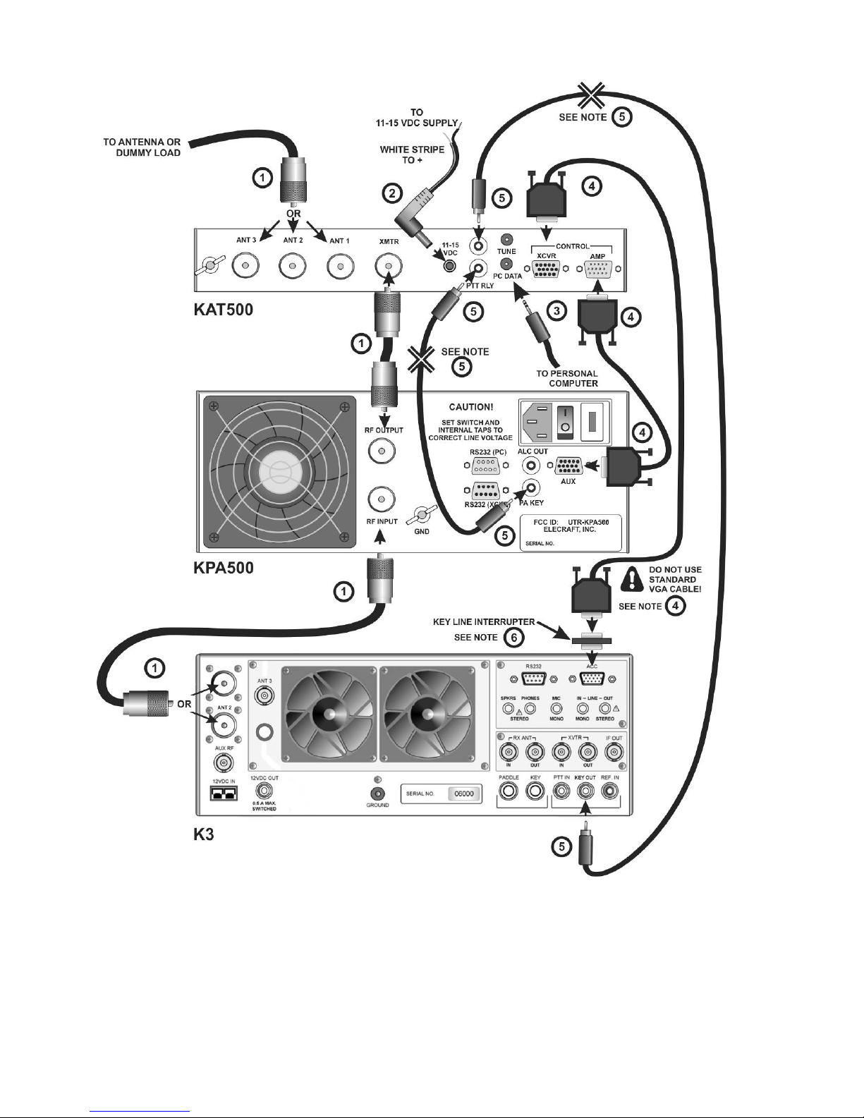
Cabling
The Elecraft K3 and KPA500 amplifier normally use the E850463 Aux interface cable that communicates
band selection and other information between the K3 and KPA500. The KAT500 can be included in the
E850463 Aux interface path and use the data to switch to the correct band along with the K3 and
KPA500. Although not strictly required, the E850463 Aux cable provides the best integration of the
KAT500, KPA500 and K3 equipment.

4
In addition to the supplied cables, you will need two E850463 Aux cables. Normally you will have one
already connected between your K3 and KPA500, so you may need one additional cable. This is the same
cable included in the KPAK3AUX cable set. You can purchase the cable from Elecraft (order E850463)
or, you can construct your own cable using male and female DB-15 connectors wired as follows.
IMPORTANT
Do not use standard VGA cables. The E850463 Aux cables are wired differently.
Table 1. E850463 Aux Cable Wiring.
CONNECTOR PINS SIGNAL
2 2 AUXBUS
3 3 BAND 1
5 5 GND
9 9 BAND 2
10 10 PTT (or KEY)
11 11 Inhibit
12 12 GND
13 13 BAND0
14 14 BAND3
15 15 ALC (Normally not used. See your KPA500 Owner’s Manual)
The basic E850463 Aux cabling setup is shown in Figure 1. If your station setup requires that other
equipment (e.g. SteppIR controller) have access to the key line to inhibit the amplifier, use the cabling
described in Figure 2.
50-ohm coaxial RF cables with PL-259 connectors.
Be sure you select the antenna output on the K3 that connects to the KPA500.
The KAT500 allows up to three antenna connections, selected from the front panel (See
Operation, page 14).
Two wire power cable with a female 2.1 mm coaxial connector.
Connect to the station 11 to 15 VDC power supply with the white striped lead to the positive
terminal.
Computer interface cable.
Not required, but used for controlling the KAT500 from a personal computer, customizing
the KAT500’s operation or for updating firmware (see Utility Program on page 20).
E850463 Aux interface cables with male and female connectors.
Do not use common VGA cables; they are not wired correctly for this use. You can order
E850463 from Elecraft or you can make your own (See E850463 Aux Cable Wiring, above).

5
Figure 1. Cabling Diagram: Elecraft K3, KPA500 and KAT500 Using E850463 Aux Interface Cables.
6
Figure 2. Cabling Diagram: Elecraft K3, KPA500 and KAT500 Using E850463 Aux Interface Cables
with Separate Key Line.

7
Key Line Cables
The Key Line (sometimes called a PTT line) controls the amplifier, enabling it for normal
transmission and inhibiting it when necessary to protect the amplifier other equipment. The
key line consists of a two conductor (center wire and shield) cable and connects to the
Elecraft equipment using RCA-type male connectors.
The K3 transceiver grounds the Key line to enable the KPA500 amplifier. Opening this line
anywhere between the K3 and the KPA500 will inhibit the amplifier. If you have an external
device that must control the key line, such as a SteppIR controller, you may insert it series
with the key line in either place indicated with the using connectors that match those on
the external device.
If you need additional cables, you can make your own or order additional cables from
Elecraft (part number E100416). The Elecraft cables use RG59 coaxial cable for optimum
shielding against incidental RF pickup.
IMPORTANT
When using a separate Key Line cable, you must:
1. Interrupt the key line in the E850463 Aux cable as described
in note below.
2. Use a separate key line cable between the transceiver and
between the KAT500 and between the KAT500 and the
amplifier. You cannot use an E850463 Aux cable in one
location and a separate key line cable in the other.
Key Line Interrupter
The E850463 Aux cable includes the key line that inhibits the amplifier when needed to
protect other equipment. This circuit must be broken when using an external key line cable or
the key line in the E850463 Aux cable will bypass the external cable and the external
equipment will not be able o inhibit the amplifier. If you purchased the Elecraft Aux cable as
part of the KPAK3AUX cable set, you received with it a small device called the Key Line
Interrupter that opens the key line. The key line is cut inside the Inhibiter so you do not need
to modify your E850463 Aux cable in any way. If you only purchased the E850463 Aux
cables you can order a key line interrupter separately. Order E850462 from
If using a homemade cable, you can cut the circuit at pin 10 (see Table 1. E850463 Aux Cable
Wiring. on page 4)

8
Icom Transceivers with AH-4 ATU Interface
Icom transceivers equipped with the interface connector for the Icom AH-4 ATU can operate the
KAT500 through the AH-4 interface.
Icom transceivers not equipped with the AH-4 interface can use the KAT500 as described under Other
Transceiver and Amplifier or Stand-Alone Transceiver on page 11.
Cabling
Cables with the proper connectors is required wired as follows.
Table 2. Icom AH-4 Interface Cable Wiring.
MOLEX CONNECTOR TO
ICOM TRANSCEIVER SIGNAL T-R-S CONNECTOR
TO KAT500 POWER CONNECTOR
TO KAT500
Pin 1 Key Tip NC
Pin 2 Start Ring NC
Pin 3 +12 VDC NC Center
Pin 4 Ground Shield Outer Shell
NOTES:
Molex Connector: Pin 1 is at the triangular end of the connector.
T-R-S is tip, ring and shield on a 3.5mm “stereo” plug. NC = No connection.
Power Connector is a 2.1mm barrel type connector. NC = No connection.
Table 3. Icom Key Line Cable Wiring.
DIN CONNECTOR TO
ICOM TRANSCEIVER SIGNAL RCA TYPE
CONNECTOR TO
KAT 500
POWER CONNECTOR
TO KAT500
Pin 3 HSEND Tip NC
Pin 2 Ground Shell NC
NOTES:
The DIN connector varies with the model of Icom transceiver. See your owner’s manual for
the specific connector required.

9
Connect the equipment as described in Figure 3 and the associated notes.
50-ohm coaxial RF cables with PL-259 connectors.
Be sure your transceiver is configured to deliver power to the antenna output that connects to
the KPA500.
The KAT500 allows up to three antenna connections, selected from the front panel (See
Operation, page 14).
AH-4 Interface Cable.
Wire the cable as shown in Table 2, Icom AH-4 Interface Cable Wiring, above.
The Interface Cable includes the Key Line (sometimes called a PTT line) which controls the
amplifier, enabling it for normal transmission and inhibiting it when necessary to protect
other equipment.
The transceiver grounds the Key line to enable the KPA500 amplifier. Opening this line
anywhere between the transceiver and the KPA500 will inhibit the amplifier.
Key Line Cables
The Key Line (sometimes called a PTT line) controls the amplifier, enabling it for normal
transmission and inhibiting it when necessary to protect the amplifier other equipment.
The key line between the KPA500 and the KAT500 consists of a two conductor (center wire
and shield) cable and connects to the Elecraft equipment using RCA-type male connectors.
The key line between the KAT500 and the Icom transceiver must be wired as shown in
Table 3. Icom Key Line Cable Wiring.
External Device Controlling the Key Line.
If you have an external device that must control the key line, you may insert it series with the
key line an either place indicated with the using the appropriate connectors to match the
external device.
Computer interface cable.
Not required, but used for controlling the KAT500 from a personal computer, customizing
the KAT500’s operation or for updating firmware (see Utility Program on page 20).

10
Figure 3. Cabling Diagram: Icom Transceiver with AH-4 Tuner Interface.

11
Other Transceiver and Amplifier or Stand-Alone Transceiver
The KAT500 works well with any H.F. transceiver covering 1.8 through 54 MHz and amplifier delivering
up to 1,000 watts output (see Specifications, page 2). If you have an Elecraft K3 transceiver and KPA500
amplifier you can connect them to the KAT500 as shown here. However, for best integration of the K3
equipment, we recommend that you use the E850463 Aux interface cable as shown on page 3 and
Figure 1.
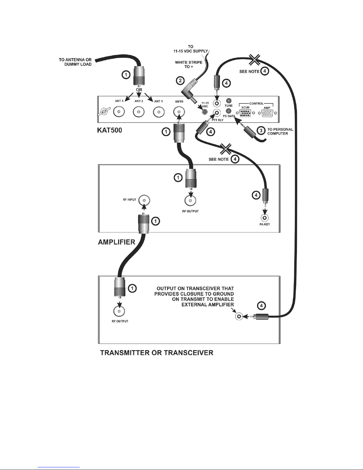
The basic cabling requirements for a transceiver and amplifier combination are shown in Figure 4.
Figure 5 shows the basic cabling for a stand-alone transceiver. Refer to the following notes for details of
the connections.
50-ohm coaxial RF cables with PL-259 connectors.
The KAT500 allows up to three antenna connections, selected from the front panel (See
Operation, page 14).
Two wire power cable with a female 2.1 mm coaxial connector.
Connect to the station 11 to 15 VDC power supply with the white striped lead to the positive
terminal.
Computer interface cable.
Not required, but used for controlling the KAT500 from a personal computer, customizing
the KAT500’s operation or for updating firmware (see Utility Program on page 20).
Key Line Cables
The Key Line (sometimes called a PTT line) controls the amplifier, enabling it for normal
transmission and inhibiting it when necessary to protect other equipment. The key line
consists of a two conductor (center wire and shield) cable and connects to the KPA500 using
RCA-type male connectors. You’ll need to equip your cables with whatever connector types
are used on the transceiver and amplifier.
If you have an external device that must control the key line, you may insert it series with the
key line an either place indicated with the using the appropriate connectors to match the
external device.
12
Figure 4. General Cabling for Transceiver and Amplifier.

13
Figure 5. General Cabling Requirements - Stand-Alone Transmitter or Transceiver.

14
Operation
The KAT500 turns on automatically when power is applied. You can turn the KAT500 off from the front
panel by holding the MODE switch. A brief tap on the MODE switch will turn the KAT500 on again.
IMPORTANT!
IF YOUR TRANSCEIVER OR AMPLIFIER HAS A BUILT-IN ATU, be sure it
is in bypass before attempting to use the KAT500.
IF YOU ARE USING THE KAT500 WITH A K3 CONNECTED USING THE
E850463 AUX CABLE (Setup Figure 1 or Figure 2): Apply power to the KAT500
before or at the same time you turn the K3 on. If you turn the K3 on first the K3 may
not initialize until you apply power to the KAT500.
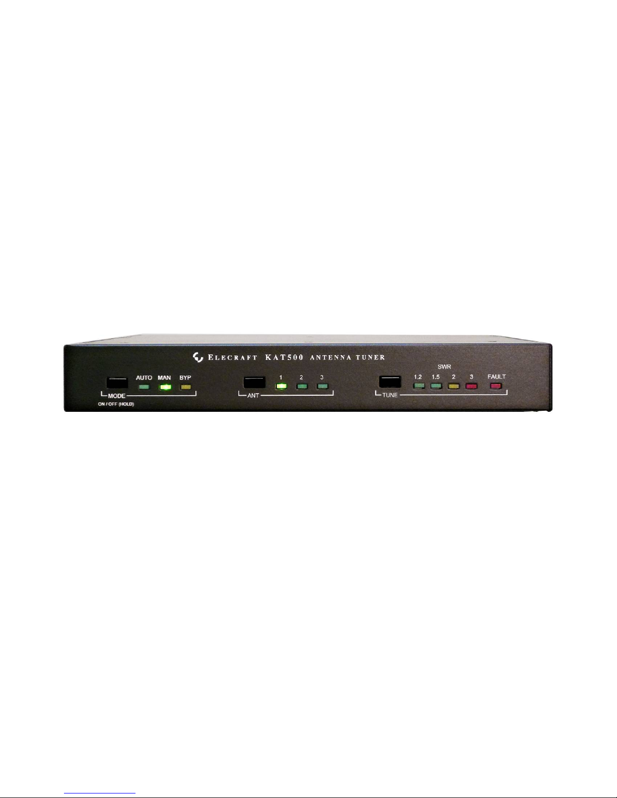
Front Panel Controls and Indicators
Figure 6. KAT500 Front Panel Controls.
The KAT500 is normally operated using the simple front panel controls (see Figure 6). Optionally, it can
be operated using the Utility program (See Utility Program on page 20).
Mode Control and Indicators. Tap the MODE switch to select:
1. AUTO (Automatic): When at least 7 watts of RF is present and the SWR is greater than a
predetermined limit, the KAT500 automatically initiates a tune cycle to find a setting that
produces a low SWR. (See Tune Operation on page 16 for a description of what happens
during the tune cycle) The predetermined SWR limit at which an automatic tune cycle
begins can be chosen using the Utility Program (page 20). The default SWR value is
1.8:1.
2. MAN (Manual): The KAT500 does not initiate a tune cycle automatically, regardless of
the SWR. If the SWR is dangerously high, the KAT500 will open the key line to disable
the amplifier. A tune cycle can be initiated manually as described under Tune Control,
SWR and FAULT Indicators below.
3. BYP (Bypass): RF is passed straight through the KAT500, bypassing the tuning elements
in the matching network. The RF does pass through the SWR bridge so the SWR seen at
the input to the antenna feed line is displayed. Also, the KAT500 will switch to the
antenna chosen for each band (see Antenna Selector and Indicators below). Whenever
power is off, the KAT500 switches to BYP and antenna 1.

15
Antenna Selector and Indicators. Until you choose a different antenna, the KAT500 uses
antenna 1 on all bands.
1. Tap the ANT switch to select the desired rear panel antenna connection: 1 (ANT 1), 2
(ANT 2), and 3 (ANT 3):
2. The antenna selection is remembered for each band, so the KAT500 will automatically
return to the chosen antenna when the KAT500 returns to that band.
3. The KAT500 switches to ANT 1 whenever the power is off.
4. Unused antenna connections have bleeder resistors that drain off accumulated static from
rain, wind, etc.
Tune Control, SWR and FAULT Indicators. Tap the TUNE switch to manually initiate a tune
operation that will search for the settings needed to produce a low SWR. To cancel a tune
operation, tap the TUNE switch a second time. When initiating a tune operation:
1. The indicator for the mode selected (AUTO or MAN) flashes.
2. If the KAT500 was in BYP mode, it will automatically switch to MAN mode.
3. The KAT500 opens the key line to disable the external amplifier provided the RF power
present is less than the limit specified for hot-switching (see Key Line Hot Switching
below)
4. The tune operation begins when 7 watts or more of RF is applied (see Tune Operation
below for details of what happens during tuning).
5. The SWR lights indicate how well the KAT500 has matched the antenna to the
transceiver. Typically an indication of 1.5 or lower is considered a good match. The
FAULT indicator will light if an abnormal condition occurs (see Fault Conditions on page
18).
6. The KAT500 closes the key line to enable the amplifier provided the RF power is below
the limit specified for Key Line Switching (see below) and the SWR is below 2.0. If the
SWR is above 2.0 the KAT500 will hold the key line open to protect the amplifier.
Optionally you can initiate a tune operation through the rear panel TUNE jack with a transceiver
using the AH-4 protocol or by momentarily shorting the ring to ground. Also, a tune operation
can be initiated through the RS232 port using the KAT500 Utility Program (page 18).
Key Line Hot Switching
The Elecraft KPA500 is designed to have its key line switched to disable or enable the amplifier even
while it is producing full RF power, but many other amplifiers may be damaged doing that. To protect
those amplifiers, the KAT500 is supplied configured so that the key line will not be switched if 30 watts
or more of RF power is present. This value may be changed to match the key line switching capability of
any amplifier using the Utility Program (see page 20).

16
Tune Operation and Memories
Tune Operation
A tune operation begins when RF power between 7 and 100 watts is applied and the SWR is above the
tuning threshold in AUTO mode, or when the TUNE switch is tapped in either AUTO or MAN modes. The
RF power must be below the key line hot switching limit (see Key Line Hot Switching, above) so the
KAT500 can disable the amplifier. The KAT500 will not respond to less than 7 watts of drive and over
100 watts will cause a fault condition (see Fault Conditions on page 18)
Relays in the KAT500 operate to search for values of inductance (L) and capacitance (C) that match the
impedance of the antenna to 50 ohms non-reactive for the transceiver.
The SWR lights indicate how close the antenna impedance is matched to the transceiver. The L and C
values switched in will provide a good match for most situations, but if you feel the resultant SWR is high
you can tap TUNE again within 3 seconds to initiate a second, fine tuning process in which smaller
changes in L and C values are tried. That may result in a lower SWR. You can also manually adjust the L
and C values using the KAT500 Utility Program (page 20).
If you have a high-Q (narrow bandwidth) antenna that benefits from a fine tune operation on certain
bands, you can configure the KAT500 to automatically do a fine tune operation without pressing the
TUNE switch again with the Utility Program (see Auto Fine Tune, page 21).
If the SWR is 1.2 or less when a tune operation begins, the KAT500 bypasses the matching network
without searching for a tuning solution. The KAT500 remains in either AUTO or MAN mode but the
matching network is switched out of the RF path (bypassed). The bypass setting will be stored as the
tuning solution so the matching network will be bypassed whenever you return to that frequency. This
SWR threshold can be changed with the Utility Program (see Automatic Bypass on Selected Bands on
page 18 and VSWR Thresholds page 21).
Memories
After successfully tuning, the KAT500 stores the L and C settings or the bypass setting in memory. They
will be recalled almost instantly when returning to that frequency later. The entire spectrum from 1.8
through 60 MHz is divided into frequency segments and tuning information is stored for each segment in
which you have successfully completed a tune operation.
When starting a tune operation for a frequency segment that has no previously stored L and C values, the
KAT500 first tries the settings in the nearest frequency segment that has tuning data.
Since retuning is normally required over a narrower frequency range on the lower frequencies to maintain
a low SWR, the lower frequencies have narrower segments assigned as follows:
Below 3 MHz the segments are 10 kHz wide.
From 3 MHz through 26 MHz the segments are 20 kHz wide.
From 26 MHz to 38 MHz the segments are 100 kHz wide.
From 38 MHz to 60 MHz the segments are 200 kHz wide.
The KAT500 also stores the antenna output that you selected for each band.

17
Frequency Tracking with an Elecraft K3Transciever
When the KAT500 is used with an Elecraft K3 transceiver, the K3 can be configured to cause the
KAT500 to follow changes in the K3’s VFO frequency during receive. The KAT500 will change to the
tuning solution for each frequency segment as the K3’s VFO frequency is tuned across the band. To use
frequency tracking:
Connect the KAT500 and K3 using the Aux interface cable as shown in Figure 1 (page 5) or
Figure 2 (page 6).
Ensure that your K3 is equipped with firmware revision 4.82 or later. See Firmware Upgrades in
your K3 Owner’s Manual for instructions about how to upgrade your firmware, if needed.
Enable the frequency tracking function at the K3: select CONFIG:KAT3 and then tap the 1switch
to toggle between KAT500N (no KAT500) and KAT500Y (KAT500 connected and frequency
tracking enabled).
Bandswitching
Elecraft K3 and KPA500 Amplifier Combination
When using the KAT500 with an Elecraft K3 transceiver and KPA500 amplifier connected with the
E850463 Aux interface cable (Setup Figure 1or Figure 2), the KAT500 changes bands when you change
bands at the K3. The mode selected (AUTO, MAN or BYP) applies to all bands. Only the ANT selection
and the L/C settings are stored in memory and recalled for each band.
Non-Elecraft Amplifiers
Change bands as follows to avoid damage to your amplifier:
Switch the transceiver to the new band.
Switch the amplifier to the new band.
Apply RF power between 7 and 30 watts (see note 1 below). This will cause the KAT500 to
change bands, switch to the last used antenna on that band (see note 2 below), switch to the
tuning values for that frequency stored in memory or perform a tune cycle, if in AUTO mode. If a
tune cycle is performed, 20 watts or more will produce more accurate tuning.
If your amplifier requires manual tuning, connect it to a suitable dummy load. (You can attach the
dummy load to one of the KAT500 antenna connectors, switch the KAT500 to BYP and select
that connector with the ANT switch.)
Tune up your amplifier into the dummy load per the manufacturer’s instructions.
When finished return the KAT500 mode to AUTO or MAN and, if needed, change back to the
original antenna selection.
Notes:
1. At 30 watts and above the KAT500 will refuse to open the key line to protect amplifiers that
cannot be “hot switched”. That is the default value. If your amplifier is capable of handling
higher powers you can change this value using the Utility Program (page 20). The KAT500
will not respond to less than 7 watts of RF power.
2. If you are not using a K3 with an E850463 Aux cable connected between your K3 and the
KAT500, you must make the KAT500 change bands by applying RF power. Only a very
Other manuals for KAT500
3
Table of contents
Other ELECRAFT Tuner manuals

ELECRAFT
ELECRAFT KAT2 User manual

ELECRAFT
ELECRAFT T1 User manual

ELECRAFT
ELECRAFT KAT100 User manual

ELECRAFT
ELECRAFT KAT1 User manual

ELECRAFT
ELECRAFT KXAT1 User manual

ELECRAFT
ELECRAFT KAT500 Installation manual

ELECRAFT
ELECRAFT KAT500 User manual

ELECRAFT
ELECRAFT KAT500 User manual

ELECRAFT
ELECRAFT KXAT2 User manual
Popular Tuner manuals by other brands

Harman Kardon
Harman Kardon HA160-0004-A owner's manual

Sirius Satellite Radio
Sirius Satellite Radio SIRIUS SiriusConnect SIR-SNY1 installation guide

Telefunken
Telefunken RT200 User information

AMX
AMX DAS-SIRIUS installation guide

Conceptronic
Conceptronic CMT2D Firmware Upgrade Instructions

Kenwood
Kenwood KTC-HR300 - HD Radio Tuner Box instruction manual


