Elecro Engineering G2 Installation instructions

G2 Heat Exchanger
Installation & Operating Manual

ENGLISH
www.elecro.co.uk
Contents
Page
ENGLISH ........................................................................................................ 1 - 13
ESPAÑOL ....................................................................................................... 14 - 27
FRANÇAIS ..................................................................................................... 28 - 41
DEUTSCH ...................................................................................................... 42 - 55
PORTUGUÊS ................................................................................................. 56 - 69
ITALIANO ....................................................................................................... 70 - 83
SVENSKA ....................................................................................................... 84 - 97
Русский ....................................................................................................... 98 - 110

ENGLISH
1
www.elecro.co.uk
Important Notes!
Congratulations on purchasing your new Elecro Heat Exchanger. Elecro
heat exchangers are manufactured in the UK, to exacting standards and
use the highest quality materials, to ensure exceptional performance and
reliability please take a moment to read these instructions. Your new heat
exchanger must be installed and operated as specied.
This heat exchanger must be installed correctly by qualied
personnel only, and in accordance with any national/ regional
requirements / regulations.
Product Overview
Standard G2 Heat Exchanger
Fig 1.
Nipple
End Cap
Coupling
Primary Coupling
Outer Tank
Blanking Cap
Nipple
Thermostat
pocket cap
1.5”/50mm Union
Expansion Springs
DO NOT ADJUST!

ENGLISH
www.elecro.co.uk
2
Specication
With optional Equipped kit
Transfer values
ΔT = Temperature dierence between Primary (Hot) and Secondary (Pool)
To calculate BTU multiply kW x 3412
kW x 3412 = BTU Output
Note: Maximum primary operating temperature is 95ºC
Primary booster
pump Digital / Analogue
control assembly
One way
valve
Flow
switch
1.5”/50mm Union
Thermostat
pocket cap
Expansion Springs
DO NOT ADJUST!
Standard
Power
Output
Primary
(HOT) Flow
(m³/h)
Primary
(HOT) Head
Loss (kpa)
Secondary
(POOL) Flow
(m³/h)
Secondary
(POOL) Head
Loss (kpa)
ΔT 15ºC (kW)
ΔT 20ºC (kW)
ΔT 30ºC (kW)
ΔT 40ºC (kW)
ΔT 50ºC (kW)
ΔT 60ºC (kW)
ΔT 70ºC (kW)
30-kW 1.1 6.1 10 5.0 9 11 16 20 26 30 33
30-kW 1.3 6.8 10 5.0 10 13 18 23 31 34 39
30-kW 1.3 6.8 14 7.0 11 15 20 26 34 41 46
49-kW 1.6 7.7 16 9.2 13 18 25 34 41 50 56
49-kW 1.8 8.3 16 9.2 14 20 28 38 45 55 62
49-kW 2.2 9.6 17 9.8 16 22 33 44 52 64 73
85-kW 2.4 11.3 17 10.6 22 28 40 53 64 75 81
85-kW 2.7 12.9 17 10.6 26 32 46 60 73 82 89
85-kW 3.2 14.7 17 10.6 28 34 49 64 77 90 102
122-kW 3.8 18.3 19 12.6 33 43 68 75 93 108 120
122-kW 4.2 20.0 19 12.6 36 48 70 89 108 126 143
122-kW 4.6 21.1 19 12.6 38 52 73 95 116 137 156

ENGLISH
Dimensions (mm) - Optional equipped kit
Dimensions (mm) - Standard G2 heat exchanger
Installation
Your Elecro Heat Exchanger can be installed either horizontally or
vertically. (Please see gures 4 / 5 ) A wall bracket is supplied for the
Horizontal installation only, see gure 6.
3
www.elecro.co.uk
L3
L2 (without unions)
L1
278
210
L1 L2 L3
30-kW 540 426 247
49-kW 710 596 417
85-kW 840 726 547
122-kW 1000 886 707
Fig 2.
Fig 3.
L3
L1
L2 (without unions)
131

www.elecro.co.uk
4
ENGLISH
With optional Equipped kit
Horizontal installation
POOL
POOL
PUMP
PUMP
PUMP
FILTER
FILTER
BOILER
BOILER
ELECRO HEAT
EXCHANGER
ELECRO HEAT
EXCHANGER
NON RETURN
VALVE
NON RETURN
VALVE
WATER
TREATMENT
WATER
TREATMENT
Fig 4.
Fig 5.

5
www.elecro.co.uk
ENGLISH
Horizontal wall mounting:
Your Elecro Heat Exchanger should be connected to the two
independent water circuits as follows:
1. Connection to Water Filtration Circuit (Secondary)
The heat exchanger should be plumbed inline, after the ltration pump
and lter and before any water treatment equipment. It should be fed
with clean water. Weed / debris should not be allowed to enter the heat
exchanger. Universal 1.5” / 50mm ABS plastic adapter unions for connec-
tion to rigid PVC or ABS pipe are included (stepped internal diameter to
accommodate both sizes). The heat exchanger should be installed as close
as possible to the boiler to minimise heat loss.
To assist with correct air purging and to ensure that the heat exchanger
remains full of water during operation, it should be installed at the lowest
point in the ltration circuit.
If the heat exchanger is installed in a vertical plain, it is essential that
the pool/pond water (secondary circuit) enters low and exits high.
Fig 6.
1. Fix the supplied wall bracket
as shown securing with
two screws (xings not supplied)
2. Hang the Heat Exchanger unit onto the bracket
NOTE: Wall bracket not suitable for Vertical
mounting
Wall bracket

www.elecro.co.uk
6
ENGLISH
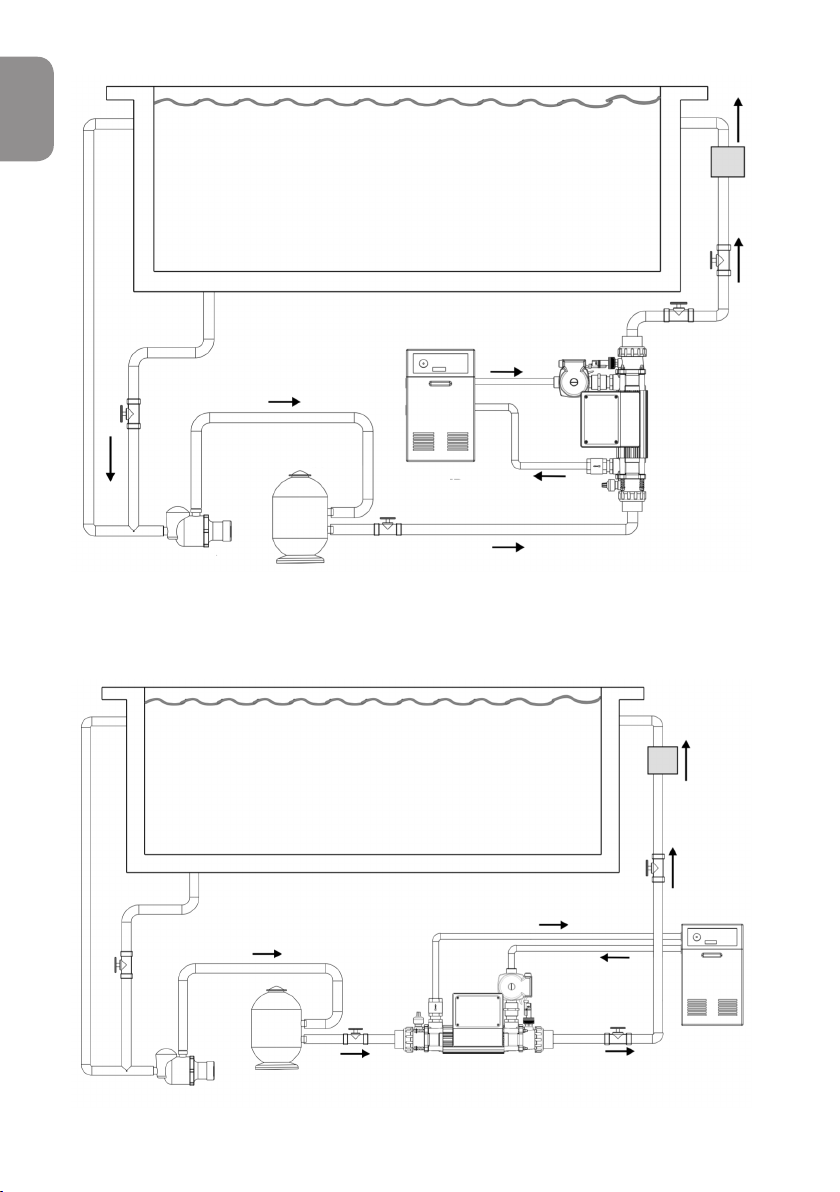
2. Connection to Heating or Cooling Circuit (Primary)
The heat exchanger should be connected directly to the primary heating
circuit i.e. boiler, via the provided 1” BSP male brass connectors, see
diagram below.
NOTE: The circulation pump of the primary circuit should be
controlled by a thermostat, which should be connected via the
ltration pump to allow heating only when the ltration pump is
running.
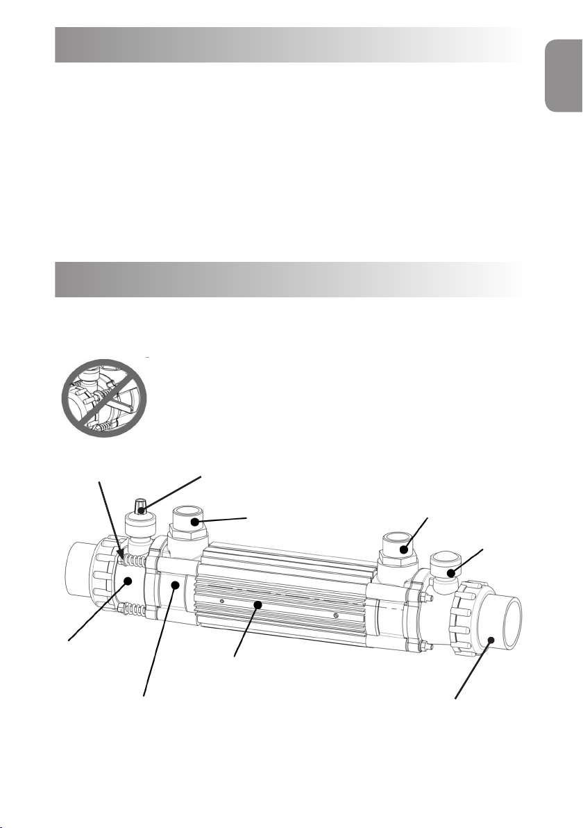
Air bleed valves should be installed at the high points of the primary
circuit. To ensure correct temperature detection, it is essential that
the thermostat / thermistor is positioned at the water inlet of the heat
exchanger. The thermostat pocket and ow switch use a common port,
and can thus be swapped as required.
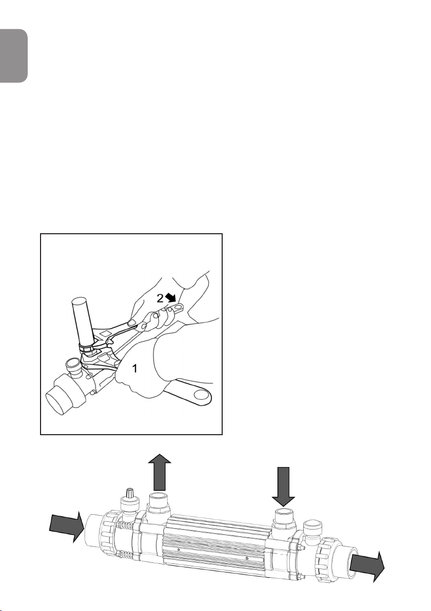
Use two wrenches to fasten ttings.
Wrench No. 1 should remain steady. NOTE: The Thermostat Control is
only included with the ’Optional’
fully equipped kit. The standard
unit is supplied only with a
Thermostat pocket and blanking
cap.
Care should be taken not to over
tighten any connections, as this
could result in damage to the heat
exchanger. Only use the supplied
brass connectors as other uncertied
connectors may leak or cause
damage to the unit.
Fig 7.
Fig 8.

7
www.elecro.co.uk
ENGLISH
Circulation direction:
The primary and secondary circuits should be installed so water ows are
counter current i.e. The hot water from the primary circuit should ow in
the opposite direction to the water in the secondary circuit.
CAUTION
If the heat exchanger is not used during winter months it must be drained
to prevent frost damage.
NOTE: For Winterising / maintenance - it is recommended that the heat
exchanger is installed with isolation valves on both water input and out-
put sides of the primary and secondary circuits. This will allow the water to
be shut o on both sides and aid removal from the system, when
required.
Water quality
To prevent damage to your heat exchanger, the water quality must be kept
within the following limits:
Chlorine Content: Max 3mg/l (ppm)
Chloride Content: Max 150mg/l
PH: 6.8-8.0
Calcium Hardness: 200-1000mg/l (ppm)
Stainless Steel heater exchangers are NOT suitable for use with salt
Water.
Equipped Heat Exchanger
(optional equipped kit)
For Elecro heat exchangers purchased with the optional equipped kit,
these include the following items:
Primary Booster Pump (Primary heating circuit)
Flow Switch
Digital or analogue temperature control
If installing with the equipped kit it is essential to take note of the
ow direction indicated on the, non-return valve and
primary booster pump.

www.elecro.co.uk
8
ENGLISH
The heat exchanger should be set up as per the following diagrams,
taking care to respect the indicated ow directions. For pool / pond water
entering on the left side of the heat exchanger, the primary water ow and
equipment should be arranged as shown in g.9.
For pool / pond water entering on the right side of the heat exchanger, the
primary water ow and equipment should be arranged as shown in g.10.
Secondary Water ow - left to right
Pump
One way valve
Thermostat
1” femal nipple
Flowswitch
Fig 9.

9
www.elecro.co.uk
ENGLISH
Secondary water ow right to left
The control box can be attached to the Elecro Heat Exchanger as shown in
the diagram above using the xings provided.
Electrical connection
Electrical connection:
Undo the lower cover screws and remove the electrical cover. All electri-
cal connections should be made into the relevant terminal block position,
according to the labelled positions.
Connection explanation:
Ensure that the Earth ring is securely connected using the Controller x-ing
bolts and washers as shown g:11 (this is then looped to terminals 3 & 6
internally).
Terminals 1, 2 & 3 connect to the mains incoming power supply as
indicated.
Terminals 4, 5 & 6 connect to the Grundfos pump supply cable as
indicated.
Terminals 7 & 8 connect to the ow switch.
Pump
Flowswitch
Fig 10.
1” femal nipple One way valve
Thermostat

www.elecro.co.uk
10
ENGLISH
For Analogue only:
Terminals 9 & 10 is the volt free switched output to control the heating
appliance.
Electrical
For Digital only:
Terminals 9 & 10 connect to the temperature sensing probe.
Terminals 11 & 12 is the volt free switched output to control the heating
appliance.
Terminals 13 & 14 is the Priority Heating volt free switched output to
control the ltration pump (explained later).
Controller instructions
For Elecro Heat Exchangers, equipped with analogue control, the control
dial should be rotated to the desired water temperature.
For Elecro Heat Exchangers, equipped with digital control. The current
water temperature is displayed in the red upper display. The lower green
display ‘required temperature’ can be selected by the user. This is the
temperature you would like your water to be maintained at.
Earth terminal ring secured
using enclosure xing
Bolts and washers
located behind the
lower access cover.
Fig 11.

11
www.elecro.co.uk
ENGLISH
Press and hold for 2 seconds to power the control on/o
Press to increase set temperature (required water temperature)
Press to decrease set temperature (required water temperature)
Press and release to activate / deactivate ‘Priority Heating’
Time switching delay
To prevent overheating of the switch components within the heating
appliance caused by frequent on and o switching (cycling), the digital
controller has been pre-programmed with a time delay function.
This prevents rapid uctuations in temperature or velocity from switching
the heating appliance on and o more than once in a two minute period.
The time delay mode is indicated by the ashing LED next to the
symbol on the digital display (gure 12).
Dierential
When the water has reached the required temperature the heating
appliance will switch o and will not switch back on until the water
temperature has dropped 0.6˚C. This value is known as the dierential and
is also in place to prevent overheating of the switch components caused
by cycling.
Priority Heating function ensures your water is constantly maintained at
the required temperature. When priority heating is activated the Priority
Heating Icon on the bottom right of the display will illuminate. The control
will now monitor the water temperature, and start both the circulation
pump and heating process when necessary.
NOTE: Priority Heating requires electrical connection to the ltration
pump contactor as shown g. 13.

www.elecro.co.uk
12
ENGLISH
Fig 12.
Inline
Priority Heating wiring schematic
Guarantee
Your Elecro heat exchanger is guaranteed for two years from the date of
purchase against faulty workmanship and materials.
ELECRO ENGINEERING LTD will replace or repair, at it’s discretion, any faulty
units or components returned to the company for inspection. Proof of
purchase may be required.
ELECRO ENGINEERING LTD will not be liable in cases of incorrect
installation, inappropriate use or neglect.
PUMP
POWER
SUPPLY
Supply in
230V
L
NContactor Connects to
terminals 13 & 14
Filtration
Pump
Pump Time Clock
Inline
Isolation Switch
A1 A2
Fig 13.

13
www.elecro.co.uk
ENGLISH
RoHS compliance statement
Elecro Engineering Limited certify that our Electric Swimming Pool
Heater Range/Heater Exchanger range complies in accordance with RoHS
Directive 2011/65/EU on the restriction of hazardous substances.
Waste of Electrical / Electronic Equipment
This product complies with EU directive 2012/19/EU
Do Not dispose of this product as unsorted municipal waste.
This symbol on the product or on its packaging indicates
that this product should not be treated as household
waste. Instead it should be handed over to the applicable
collection point for the recycling of electrical and
electronic equipment.
By ensuring this product is disposed of correctly you will
help prevent potential negative consequences for the
environment and human health, which could otherwise
be caused by inappropriate waste handling of this product.
The recycling of materials will help to conserve natural
resources. For more information please contact your local
Civic oce, your household waste disposal service or the
retailer where you purchased the product.

www.elecro.co.uk
14
ESPAŇOL
Notas importantes
Gracias por adquirir el nuevo intercambiador de calor Elecro. Los
intercambiadores de calor Elecro se fabrican en el Reino Unido de
conformidad con las normas más exigentes y utilizando los materiales
de la más alta calidad. Con el n de obtener un rendimiento y una
abilidad excepcionales, le rogamos que dedique unos minutos a leer
estas instrucciones. Su nuevo intercambiador de calor debe instalarse y
manipularse de la manera que se especica aquí.
Este intercambiador de calor debe instalarse correctamente. La
instalación debe llevarla a cabo personal debidamente cualicado
y realizarse de conformidad con los requisitos y reglamentos
nacionales y regionales.
Visión general del producto
Intercambiador de calor G2 estándar
Fig 1.
BoquillaaBoquillaa
Acoplamiento
de la cubierta
Acoplamiento primario
Carcasa exterior
Tapón
Tapa de
la caja del
Racor de conexión de
1,5”/50mm
Muelles de expansión
¡NO LOS MODIFIQUE!

15
www.elecro.co.uk
ESPAŇOL
Especicaciones
Con kit de complementos opcional
Valores de transferencia
ΔT = Diferencia de temperatura entre el agua del circuito primario
(caliente) y del secundario (piscina)
Para calcular BTU, debe multiplicarse kW x 3412
kW x 3412 = BTU saliente
Nota: La temperatura primaria máxima de funcionamiento es de 95ºC.
Bomba elevadora
de presión Conjunto de
control digital / Válvula
Interruptor
de caudal
Racor de conexión de
1,5”/50mm
Tapa de
la caja del
Muelles de expansión
¡NO LOS MODIFIQUE!
Potencia
de salida
estándar
Caudal
primario
(CALIENTE)
Pérdida
de carga
primaria
Caudal
secundario
(PISCINA)
Pérdida
de carga
secundaria
ΔT 15ºC (kW)
ΔT 20ºC (kW)
ΔT 30ºC (kW)
ΔT 40ºC (kW)
ΔT 50ºC (kW)
ΔT 60ºC (kW)
ΔT 70ºC (kW)
30-kW 1.1 6.1 10 5.0 9 11 16 20 26 30 33
30-kW 1.3 6.8 10 5.0 10 13 18 23 31 34 39
30-kW 1.3 6.8 14 7.0 11 15 20 26 34 41 46
49-kW 1.6 7.7 16 9.2 13 18 25 34 41 50 56
49-kW 1.8 8.3 16 9.2 14 20 28 38 45 55 62
49-kW 2.2 9.6 17 9.8 16 22 33 44 52 64 73
85-kW 2.4 11.3 17 10.6 22 28 40 53 64 75 81
85-kW 2.7 12.9 17 10.6 26 32 46 60 73 82 89
85-kW 3.2 14.7 17 10.6 28 34 49 64 77 90 102
122-kW 3.8 18.3 19 12.6 33 43 68 75 93 108 120
122-kW 4.2 20.0 19 12.6 36 48 70 89 108 126 143
122-kW 4.6 21.1 19 12.6 38 52 73 95 116 137 156

www.elecro.co.uk
16
ESPAŇOL
Dimensiones (mm) - Con kit de complementos opcional
Dimensiones (mm) - Intercambiador de calor G2 estándar
Instalación
Su intercambiador de calor Elecro puede instalarse tanto de manera
horizontal como vertical (véase guras 4 y 5). El intercambiador viene de
fábrica con un soporte para instalar el aparato en la pared de manera
horizontal solamente; véase gura 6.
L3
L2 (sin racores)
L1
278
210
L1 L2 L3
30-kW 540 426 247
49-kW 710 596 417
85-kW 840 726 547
122-kW 1000 886 707
Fig 2.
Fig 3.
L3
L1
L2 (sin racores)
131

17
www.elecro.co.uk
ESPAŇOL
Con kit de complementos opcional
Instalación en horizontal
PISCINA
PISCINA
BOMBA
BOMBA
BOMBA
FILTRO
FILTRO
CALENTADOR
CALENTADOR
INTERCAMBIADOR
DE CALOR ELECRO
INTERCAMBIADOR
DE CALOR ELECRO
VÁLVULA
ANTIRETORNO
VÁLVULA
ANTIRETORNO TRATAMIENTO
DEL AGUA
TRATAMIENTO
DEL AGUA
Fig 4.
Fig 5.

www.elecro.co.uk
18
ESPAŇOL
Instalación en horizontal:
El intercambiador de calor Elecro debe conectarse a los dos
circuitos independientes de agua de la siguiente manera:
1. Conexión al circuito de ltrado de agua (secundario)
El intercambiador de calor debería instalarse de manera que quede
integrado en el circuito después de la bomba de ltrado y del ltro y
antes de cualquier equipo de tratamiento del agua. El agua que llegue
al intercambiador debe ser agua limpia. Debe evitarse la penetración de
hierbas o partículas en el intercambiador de calor. El intercambiador viene
provisto de racores adaptadores de plástico ABS de 1,5” / 50mm para
conectar el aparato a tuberías rígidas de PVC o ABS (el diámetro interno de
los racores es escalonado para poderlos adaptar a ambos tamaños). Con
tal de minimizar la pérdida de calor, el intercambiador debe instalarse lo
más cerca posible del calentador.
Para contribuir a que la purga del aire se realice correctamente y
garantizar que el intercambiador de calor esté constantemente lleno de
agua mientras esté en marcha, éste debe instalarse en el punto más bajo.
Fig 6.
1. Instale en la pared el soporte provisto
tal y como se muestra en la ilustración
utilizando dos tornillos (no incluidos).
2. Coloque la unidad intercambiadora de calor en
el soporte
NOTA: Este soporte de pared no es adecuado
para la instalación del aparato en posición
vertical
Soporte para
pared
Other manuals for G2
2
Table of contents
Languages:
Other Elecro Engineering Industrial Equipment manuals