Power Tec 71539 User manual

INSTRUCTION SHEET
71539 Drill Press Table 14" x 24" with
Fence System
21_0303
QUESTION...
1•847•780•6120
WARNING
This product is to be used with a drill press. Before using this
product, always read, understand and follow the instructions
and safety warnings in the owner’s manual for the drill press. If
you do not have the owner’s manual, obtain one from the tool’s
manufacturer before using it with this product.
You must be familiar with the use of any tool or accessory used
with this drill press table/fence system. The supplier cannot be
held responsible for any accident, injury or damage incurred
while using this drill press table/fence system with any tool.
It is the responsibility of the purchaser of this product to ensure
that any person using this product reads and complies with all
instructions and safety precautions outlined in this manual and
the operating manual of the tool being used prior to use.
CAUTION
Do not modify or use this drill press table/fence system for any
application other than that for which it was designed.
WARNING
• To avoid serious injury, turn off and unplug the drill press
before attaching, adjusting or changing accessories.
CAUTION
Think safety! Safety is a combination of operator common sense
and alertness at all times when tool is being used.
WARNING
Do not use the drill press table/fence system until it is completely
assembled and you have read and understood this entire
operating manual and the operating manual of the tool being
used with this drill press table/fence system.
SAVE ALL WARNINGS AND INSTRUCTIONS
FOR FUTURE REFERENCE
PACKAGING CONTENTS
ITEM DESCRIPTION QTY
A Multi T-Track Fence 1
BTable 1
CRemovable/adjustable Insert 1
DAdjustment Screws (Table Insert) 4
E71083 POWERTEC T-Track
Hold-Down Clamp
4
F71367 POWERTEC 3" Fence Flip Stop 1
GL-Shaped Multi T-Track Brackets 2
Figure 1
A
B
C
F
D
E
G
ASSEMBLY
Table Insert
Refer to Figure 2–3
1. There is an opening in the table for the insert, thread the
four adjustment screws into the recessed area of this
opening as shown in Figure 2.
Adjustment Screws
Figure 2
Adjustment Screws

2. Place the insert into the opening and check with a straight
edge. Use a Phillips screw driver to adjust the screws until
the insert is flush with the top of the table.
10
9
8
7
6
5
4
3
2
10
321 4 5 6 7 8 9 10 11 12 13 14 15 16 17 18 19 20 21 22 23 24 250
Figure 3
Table Insert
Table
Table
Refer to Figure 4–6
The POWERTEC 71539 drill press table features a T-Track
system that allows for quick and secure mounting to most sizes
and styles of drill press tables.
1. Place the table on top of your existing drill press table
and determine the best position based on your drill press
and requirements. NOTE: The insert opening is not in the
center of the table. The shorter side of the table should be
positioned towards the column as shown in Figure 6.
-For drill presses 12" or larger - center the table
opening on the drill press chuck in both directions.
-For drill presses 12" or less - center the table
opening left to right and push the table back against
the column.
-For drill presses with a table 9" wide or less, slide the
T-Bolts on two of the supplied 71083 POWERTEC
T-Track hold-down clamps into the lower table
T-Track slots and clamp directly to the existing table.
Figure 4
Existing Drill Press Table
71083 POWERTEC T-Track
Hold-Down Clamp
Lower Table T-Track Slot
T-Bolt
-For wider slotted tables - Place the T-Bolts on the
supplied 71083 POWERTEC T-Track hold-down
clamps through the slots (on the bottom of existing
table) and clamp directly to the bottom of the
existing table.
Figure 5
71083 POWERTEC T-Track
Hold-Down Clamp
T-Bolt Slot in Bottom of
Existing Table
Attach the Fence
Refer to Figure 6–8
Use the multi track brackets with knobs and T-Bolts to attach the
fence to the drill press table's T-Tracks.
1. Slide the T-Bolts into the upper table T-Track slots,
assemble the brackets, washers and knobs as shown in
Figure 6.
Figure 6
T-Bolt
Washer
Knob
Bracket
Upper Table T-Track Slot
Position the shorter side of
the table to the column

2. Slide two additional T-Bolts into the bottom T-Slot of the
extruded fence, place the T-Bolt through the open slot in the
bracket and assemble the washer and knob.
NOTE: The fence has a 24" laser etched scale and can be
used on either side of the workpiece as required. Simply
reverse the fence.
Figure 7
Bottom T-Slot
of Extruded
Fence
Open Slot in
Bracket
Knob
Washer
Etched
Scale
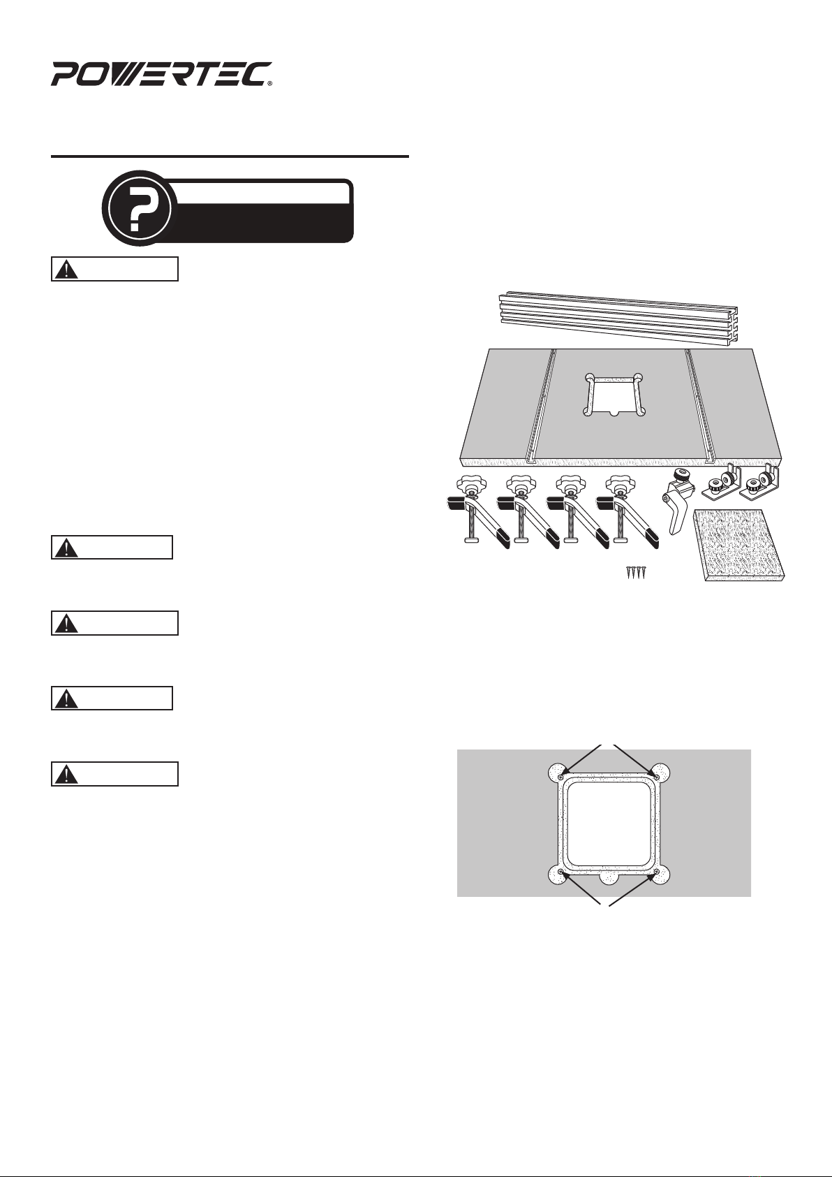
3. Position the fence perpendicular to the drill press table
T-Track, use a tape measure to make sure each end of the
fence is the same distance from the end of the table.
2
1345678910 11
Figure 8
4. When in position, tighten all four knobs of the brackets.
Flip Stop
Refer to Figure 9 and 10
The POWERTEC 71367 3" fence flip stops are extremely
versatile and quickly convert from inboard to outboard
position for a variety of applications. In addition, the flip
arm can be moved from right to left to match your feed
direction requirements.
• Slide the T-Bolt on the bottom of the flip stop into the T-Slot on
the top of the fence. See Figure 10.
• In the inboard position, the stop works with the supplied multi
T-Track fence and functions as an easily adjustable stop.
• In the outboard position, the body rotates and the flip arm
moves out. In this position the stop can work with the supplied
multi T-Track fence and a 3/4" sacrificial wood board.
To Convert from Inboard to Outboard Position
Remove the knob and T-Bolt and rotate the stop body 180°.
Replace the knob and T-bolt. See Figure 9.
inboard outboardtransition
Figure 9 Knob
Stop Body
T-Bolt
Hold Down Clamps
Refer to Figure 10
Slide the T-Bolts on hold-down clamps into the upper table
T-Track slots and clamp as required.
Figure 10
Hold-Down
Clamp
Upper Table
T-Track Slot
Flip Stop
T-Slot
TIPS
• Turn the feed handles on the drill press to makes sure they do
not interfere with the fence system. If needed, one or more of
the feed handles may need to be removed.
• Periodically check and make sure all knobs are tight
and secure.
• Clean the drill press table/fence system after each use:
-Wipe the drill press table and vacuum all T-Slots in
the table and fence.
-To prevent condensation and rust between the two
tables, DO NOT leave the drill press table mounted
on the drill press for long periods of time.

Southern Technologies, LLC
Waukegan, IL 60087
Put these instructions and the original sales invoice in a safe,
dry place for future reference.
Visit us on the web at www.powertecproducts.com
Other Power Tec Industrial Equipment manuals