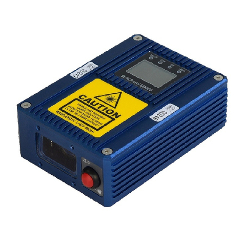
Electac MT800 User manual

FUME CONTROL EQUIPMENT
THE SAFEST WAY TO WELD
MTSOO & MT9OO MANUAL
manufactured by:
ELECTAC
Unit 7 /B,Studland Estate, Ball Hill,
N ewbU ry, berks. RG 1 5 OPO
Tel: (0OSS) 254900 Fax: (0635) 2s4OB2

ELECTAC MT800 and MT900 WELDING FUME FILTBR
INTRODUCTION
Your MT800 or MT900 is a portable welding fume filter that uses a three stage
filtration system to filter welding fumes and return cleaned air to the work area.
The spark trap collects heavy particles, slag, pieces of mig wire etc. The fibreglass
insert inside the spark trap is supported by a steel gavze and stops sparks and very
hot pieces from damaging the main filter. It is important that the fibreglass is in good
condition and fitted correctly. Failure to replace the fibreglass when it is worn or
eaten away by hot sparks or molten metal can result in damage to the main filter or
in extreme oases a fire.
The disposable main filter cartridge, filters the welding smoke to 97oh efficiency,
99.996% to British Standard 3928 if the optional Hi-Efficiency filter is used.
MT800's have a single 1100 watt by pass motor, and MT900's have twin 1100
watt by pass motors to give extra suction and superior airflow.
OPERATION
Before operating your machine, it is important to check that your power supply is the
same as the machine, and that a suitable plug is fitted. All machines must be earthed.
Your machine is assembled at the factory, all that you have to do is to attach the flexible
hose to the spigot on the spark trap using the hose clip provided. The other end of the
flexible hose should be attached to anozzle with magnet, mig torch attachment, or the
take offspigot of mig extractor torch.
FILTER FULL LIGHT
All MT800 and MT900 models are now fitted with filter full indicators. This light is
situated adjacent to the on-offswitch. When illuminated the main filter cartridge should
be replaced immediately. It is always advisable to replace the fibreglass in the spark trap
at the same time as the filter cartridge.

ELECTAG
FUME GONTROL EQUIPMENT
THE SAFEST WAY TO WORK
FACTORY EXAMINATION OF LOGAL VENTILATION PLANT FOR THE
GONTROL OF SUBSTANGES HAZARDOUS TO HEALTH REGULATIONS
1988
Description of Plant
ModeL
Fan Tylpe
FiLter Type
Motor Power
Measured Airflow
Air Velocity
Perfor:mance
Equipment condition
SeriaL No.
P1ant Loeation
Date
Portable welding fume filter/fan unit
with flexible hose forrtat sourcerr
capture ( and capture nozzl-e)
MT900 single operator
Twin turbi-ne
Disposable cartridge
2.2 kW.
465m3 /hour
39m/sec @ 55mm0 hose end
B.Om/sec @ end of nozzle 200x80mm
Pass
New
206L6s
Welding Equipment & Cutting Servlces
Sheffield
2 February, 2004
P1ease note that equipment should be reteeted every L4
months. To arrange a retegt please contact:
ELEGTAG Ltd.
Unit 7 & 8, Studland Estate
Ball Hill, Newbury
Berkshire. RG2O OPW
Tel: O{635-254900 Fax: 0{635.2540A2

SWTTCH POSITIONS FOR DIFFERENT MACHINES
On Off
MTSOO
Auto Off
on/off Manual
on
MT800 fitted with auto
on/off relay
one Motor off Two motors
MT9OO MT900 fitted with
Auto on/off relay
USING THE FUME FILTER
MT800 and MT900 welding fume extractors can be used with a magnetic nozzle, with
a Mg torch attachment, or with a Mig extractor torch.
When used with the magnetic aoz,zle, the nozzle should be placed as near to the welding
arc as possible.
All.5"'^-
Auto on/off
two motors off Manual.
on two motors
tt2
\
i
tu )
n@>

)64
v
If the Mig torch attachment is used, it should be clipped onto the Mig nozzle
approximately 25mm from the end of the torch shroud. If weld porosity is experienced,
move the attachment further up the torch shroud.
When welding in combined situations, the attachments can be pushed either 90 degrees
to the left or the right to avoid porosity.
It is usually best to fix the 20mm diameter extraction hose to the Mig torch lead with tape
allowing a small loop where the extraction hose goes over the operators hand.
When using a Mig torch with built in extraction, follow the torch manufacturers
instructions, after connecting the extraction hose to the spigot adjacent to the Euro
connector ofthe torch.

i
I
I\
li
t
r
I
::
I
fi
,
1
f.
l"
t.i
I
MATNTENANCE
SPARK TRAP
In the spark trap of the MT800/I\4T900 is a
metal gauze and fibre glass surround. The
fibre glass surround should be cleaned every
1-2 days of welding depending on the size
of electrode or wire being used. If this fibre
glass becomes damaged, renew it im-
mediately. Failure to do so could result in
damage to the main filter. New fibre glass
surrounds are available from your dealer.
2. NEW FILTER
If the spark trap fibre glass has been cleaired and the suction of the machind is
poor, this indicates that a new filter is required.
Changing the filter cartridge
a) Switch offthe motor and disconnect from the mains.
b) Release the securing clips of the spark trap and remove the spark trap
and front plate.
c) Dispose of the used filter and fit a new filter(a smear of liquid soap on
the neoprene seal of the filter assists this operation.)
d) Push the front plate/filter assembly into the machine, ensuring that the front
pressure pipe is relocated in the rubber grommet in the front plate and
protruding into the spark trap.
e) Put the spark trap in place and secure with the clips.
0 Connect the machine to the mains and switch on.

3. CARBON BRUSHES
1
The carbon brushes in the motor should be changed after 1000 working hours from
new, and subsequent changes should be every 800 working hours.
T'itting New Rrushes
a) Switch offthe unit and disconnect from the mains
b) Undo the 4 no. M6 dome nuts that hold the back plate and swing the back plate
assembly to one side. This will enable access to the motor brushes.
c) Bend back the tags as shown in the above diagram, snip offand pull out the used
brushes.
d). Slide in the new brushes, ensure that the triangular catches on the side of the brush
holders locate in the slots of the caps.
e) Replace the machine back plate and secure with the dome nuts.
Connect the machine to the mains and switch on.
0
'I
r
I
:l
i

t
t
I
t
MTsOO/9OO SPARE PARTS LTST
DRG.NO PART NO DF'SCRIPTION QUANTITY
required per machine
1
2
J
4
991000
999001
999002
9990021A
991003 I
999004
99800s
998006
998007
998008
1009
l0l0
99t012
991014
991013
991015
998016
998017
9980rs
998018
998019
999020
999021
999023
998024
998025
2026
1026
9030
2031
2032
103 1
998026
998027
998028
998029
998030
99803 1
Carbon Brushes
Sheet metal case
Course Separator
Front Plate
Gauze
Hose Clip
Rubber foot
Foot Screws
Handle
Handle Screws
Filter FES
Filter FEH
Switch MT800
Switch MT900
Motor/Fan Assey 240Y By Pass motor
MotorlFan Assey 1lOV By Pass motor
Rubber Seal
Indicator light 240V
Indicator light l15v
Mounting screw
Grommet
Mains Lead
Back cover
Back Plate
Black Plate Foam
Back Cover Screws
65mm hose
45mm hose
65mm x 40mm reducer
65mmx45mm-45mmYpiece
65mm x 45mm reducer
Fibre glass insert FB I
Pressure sensor
Front sensor pipe
Rear sensor pipe
Retaining studding- 1 1 0mm.
Studding nuts
Cap nuts
214
I
I
1
1
2
4
4
I
2
1
1
1
1
u2
l2
l2
5
6
6
7
7
8
8
9
10
10
11
1
I
I
I
8
I
I
I
I
I
4
J.
J,
I
I
1
1
1
1
1
4
1
4
t2
6
J
4
I
1
I
,
I
I75m
75m
15
0

Motor I
Motor 2
Switch
-H
-cF
{a
Pressure switch
cg
t<
()
zFilter tull light
Live
WIRING DIAGRAM MT9OO
Pressure switch
Switch Filter tull light
Motor
Neutral
Live \\/TRING DIAGRAM N'I'I'8OO
.l
iI
I
I
II
{
J
1
rt
-)t
I
1
I
I
I
I
I
,!
I
t
l
i

rl
I
PURCIIASE REOIIISITION ORDER
r
\
Ur
On^b€nsl-s^ 9,/e-l(q-
u(asf 60 ?oorr$v* vuasl".S *y1rurL70r(.
\4.
SUPPLIER: ACCOUNT No :
DEL TO :ORDERNo:
BY: NOMINAL CODE:
AUTHORIZATION: DATE:
ITEM DESCRTPTIQN QTYREQ UNIT COST DATE REQ TOTAL
COST
LvecTac- M(nso
6\yq€ 6x'f0^p.c-ro(l
-<PAa<. I
A
ll
(= rS .-<o
II
I)'t
)5'u7rs Lt ( lA' cro \
IA) > 7J . ci'n
I!
l, I
4,L /L. .ro .
\.t
-\

Welding Equipment And Cutting Services Ltd
69 Tyler Street,Sheffield,South Yorkshire S9 1DH
Tel 01 142494141 Fax 01142490599
www.wecs{td.co.uk
WE ARE MOVING
uttlng
eMces Lro
I
PLEASE NOTE THAT AS FROM 24.1.05 WE ARE MOVING TO
NEW I.ARGER PREMISES.
PLEASE FIND BELOW OUR NEW DETAILS:
WELDING EQUIPMENT AND CUTTING SERVICES LIMITED
69 TYLER STREET
SHEFFIELD
SOUTH YORKSHIRE
59 1DH
TELEPHON E: 01 1 4 2424242
FAX: 0114 2424142
THANK YOU.
Master Distributor ForAll SAF and OERLIKON products
SAFOERLIKON National Equipment Service And Repair Centre ltrDllfol

';1,1i$uh #lrl"J aglcir"is8 gniilu0 bn.{ rnsrnryiunl EitrihioW
i r.il | 0e sr iita,t: rY rllr ru?, . Ir;eilierit, isei'ii& i6 t\.'T 0d
ggf tg},ss ' I vr .t;1 I F i' [0rrS$ l i .; .;;i'
>l u . og. btl -acsw.w\rt^il
.#b,IIVOfuI trF{A ilW
OT Oktlv0Irfi mfiA 3\&' *CI. f'.t\S lUC.fiE eA "fAh{T 3TOi4 SAASJ9
.ailelrvisHq fi 3CIfiAj W3t4
:eJlAT:${] UVII4 fiUCI WOJSS Ol4ll SAAIJq
03Tt Rit Ii e3 0 IVfi 3A O L4 ITTU 3 G 1,,1A T$43 M q I U03,9 yl I tlj 311f
]'H3fiTA fi3jYT e0
fi-l3lTq314t
SFIIh{AXfiOY HTUOE
HfiT EE
s.sSFS$s $f l0 :3l4OHq3J3T'
SII'SSSS Sf l0 :XAT
IJOY )it4AI"-11"
:l'iutlo:{ .4t}ai.ill,JO il:rr, ilr'{ rl/. ,i!'l :r)lf.rrjr; r',?i!: t';l;;i;li!
c:trr!i) 'ti;;rytQf LIrl,,::i;'i ,i h;Jilrlir , .l ii,rloitnll i'1()ii: i!:,'i(l'r/ /,
uffi#$j

i
SHEFFIELD
ENGLAND
SILVERWARE
CARRS OF SHEFFIELD (MANUFACTURING) LIMITED
' Troy House, 2 Holbrcjok Avenue, Holbrook, sheffield s20 3FH, Englancl.
Telephone: +44(o)Lt4251.0610 Fax: +44(o)tL4z51.o68j SalesofficeFax:i44(0)114 z5toB75
E.mail : customer.services@ carrs-of-sheffield.co.uk
www. cars-of-sheffield. co.u k
C SoUtJ C$-1-'' 6 Nf \"-\,€-.C,a .
(p>< N" o\\\2 \+1 o Sn1,
Qosr Sl*tus-\ UH\-r,Av6a AF Q\AS Sru{eR- i
3o /, to*
?r**== S.r?P.y 1-
Ex -(rz-n<c-lo R q*11 o trts et^ fugfr,Aq .s.lta€
11o Mr \cso I z2\_o.
S{t<. 6B se\6< \\o Zq \ 5 3
\*lt("\ t'ts.e.*rW s
C
I.l(\\y\'
tu r
I

S+x. Dtt L+loa1.q.
Illt!-qua",:nil!&_q!rs ,II
1^r <rDin D,S5e 0r- it+)' N Otu) t(
e,€A 4u.Ur\Lst'l!a'l't_0.N_u-sI_U&L-l:
liLJl'trltIt( :
, ..lt
-tf '.
r.,tiLt vLl( 1.o
ttt:QUliS't UD Ili,
Au'iltotuzn.i
' ,* .."
I\
s" .rZ€U( ..__ ACCt)UN'l'N()
0l(Dtll( I'tu :zs3
NOIVIINAL CODI.,
l)A'l'Lr :
l't'tinr
I)ti.SctUl,'t't oN
M(::r*> 0on:rnau6
t{"bgu (r*-r€
LZ4o
(
:,.1
\o
L
r)
t
Io c.-) (Jxr \-f
t+6sc qrrzix
r-iilhnE
l(l.iQUltU.rl) UNI'I'
cos'l' l(tiQUll(Et)
DA'l'11 'I'()'r'n t,
c0s't'
\3( {\
(;ltn l.Jt)'t'(') t'r\ I r

FUME CONTROL EQUIPMENT
THE SAFEiST WAY TO WELD
rrG t

2

I
I
I
P\,
operator twln motor
welding fume filter
100 watt motors
a
o
a
5or 22012301240 volt
ve range of
MT800 and
portability and
A
welding
MT9OO are
flexibility are required. Both machines can be
used with nozzles with magnetic upstands and,
System Ref. ',, Part No.
MTSOO fume filter
filter
x,45mm dia.
NOT INCLUDED.
115 volt:
220/240 vok:
Portable TWIN
standard filter
2 x 3.75m x 45mm dia.
NOZZLE NOT INCLUDED.
115 volt:
2201240 vok:
Part No.
277L
2242
1110
1240
welding fume filter
2 x 1100 watt motors
Prefilter, standard
Hose 3.75m x 55mm
NOZZLE NOT
115 volt:
2201240 vok: 110
2240

Filter System
'T.hc we ll-proven filtration s\/steln tlses |l s1-rrll-k
trilp to ct'lptLrre spirrks and hear.'r' pirrticlcs. Thc
nririn disl-rosable filter cartriclge caprtr-rrcs thc
rvclding sr-noke particul:lte.
Cooling System
A rnirjor cirLlse of premtrture f,rilr-rrc itr portablc
filter units is that thev rut-t loo hot clltc to trot
enough trir passing tl-rroLrgh the tttotttrs,
p:rrticularly wl-ren they' itre Lrsecl rt'irh rVllCi
extractor torches. To prrcl'ct-tt this hrrFtl-rgr1i11g,
ELECTA(l now Lrsc [r,vc-1'r,tss ttrotors, rvhich
take ir sepllrittc sLrpply of rtir to cool the
motors l-ronr that passing rhror,rgl-r the filrer
Sprt rk t rrr ;r
I
I
I
I
I
i
sYStent
l'r[.r. g,lrtss
l.rc irlrcr
Strrnrlrrrtl \l,rin lrrltcr
(l l iuh cf Iie re rrcr or
stlrnclrrrtl rvrtlt ;rctir c
chlrrcr,ltl ,rlsrr
:r v rr ila hlc )
fl
Accessories
A varierv of rrozzles rtttcl cxtrrrctittt-t attirchments
irre available for thc F-t-EC.'l-A(i portttble funre
extrrlct()r's.
Nozzles for the MT800 and
MT900 double operator
FN200 200mrn lvide fantail
FN300 300mm rvicle far.rtail
DN120 1?0um dia clish
Nozzle for the MT900
FN900 200nrnr rviclc frintail
All the abovc nozzlcs arc
complete with a magnet.
MIG Torch attachment.
Auto On/Off sensor using the
earth lead of the welder.
Tbchnical dtct
Width 255mm 255mm
Airflow 170m3/hour 340m'/hour
- @ 400mm WG -
I
I
iI
I
I
I
Hose size 45mm dia
Various
Filtration
(BS3e28)

MOEFT
ELECTAC rrobile filters have given rnany
years of trouble-free service in the most
clerrta rtd i ng c( )nd itiolrs ti rr tttanv conrpan ies
rhrourghor.rt the \World. The rugged steel
coustruction, the easy-to-adjust arm and the
lar:ge diarneter wheels are just a few features
that ha','e nacle these machines populal in
lilrge :rncl srnall rvorksl-rops. Available with
either nrecharnicrrl or electrosratic filters and
with a choice of ar-r-r-r lengths in single or clouble
ope[ator \/ersloTrs.
5

*.r F
Electrostatic - E Range
o Heavy duty industrial electrostatic cells
. No filter replacenlents. Filters easily washed
o Quiet operatiorr using a double inlet
centrifugal fan
o Door interlock protection - opening the cell
door cuts off the high voltage to the cell
o Fault indicator
. Double operator machine available
. Choice of self-supporting anrls:
Solid aluntinium tube constructittn uith
flexible joints (A type) or
Lighttueight flexible hose ruith internal
support (l- t1'pe)
. Choice of arm lengths - 2.5 metre, 3 nletre
or 4 metre
. Remote control frorn the hood ancl low
voltage light in the end of the l'rood available
Mechanical - EM Range
. Industrial standard mechanicill filter - easily
replarced
. Fif ter efficiency 99.996"1'
r Qr-riet operarion using zr double inlet
centrifugal fan
. Double operzltor machine available
. Choice of self-supportlng arms:
Solid aluminium tube construction with
/Texible joints (A type) or
Lightweight flexible hose with intcrnal
support (L rype)
. Cl-roice of arm lengths - 2.5 metre, 3 metre
or 4 metre
o Remote control fron-r the hood and low
voltirge light in the end of the hood available
. Recomrnended for stainless steel
Technical Data
Cabinet Dimensions: 970mm x 525mm x 515rnm
Weight: Kg
Motor: E1 & EM1: 0.75kW
E2 & EM2: 1.1 kW
E1 & EMl
E2 & EM2 1 900m'/hour; free blowing
2 1 60m'/hour, free blowing
6
Airflow
This manual suits for next models
1
Table of contents

