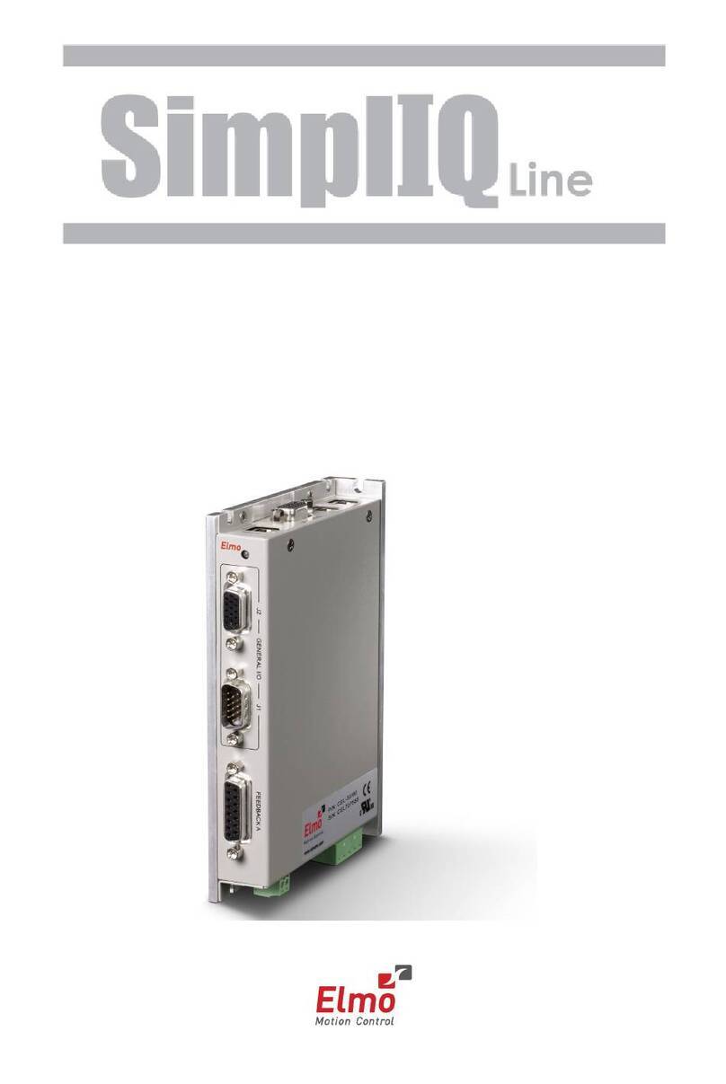
NSK MEGATORQUE M-ESA-Y2005V25 User manual

-~
ARTISAN
®
~I
TECHNOLOGY
GROUP
Your definitive source
for
quality
pre-owned
equipment.
Artisan Technology
Group
Full-service,
independent
repair
center
with
experienced
engineers
and
technicians
on staff.
We
buy
your
excess,
underutilized,
and
idle
equipment
along
with
credit
for
buybacks
and
trade-ins
.
Custom
engineering
so
your
equipment
works
exactly as
you
specify.
•
Critical
and
expedited
services
•
Leasing
/
Rentals/
Demos
• In
stock/
Ready-to-ship
•
!TAR-certified
secure
asset
solutions
Expert
team
ITrust
guarantee
I
100%
satisfaction
All
tr
ademarks,
br
a
nd
names, a
nd
br
a
nd
s a
pp
earing here
in
are
th
e property of
th
e
ir
r
es
pecti
ve
ow
ner
s.
Find the NSK ESA-J1003AFD-20 at our website: Click HERE

MEGATORQUE®MOTOR SYSTEM
User’s Manual
(ESA25 Driver Unit System)
Document Number: C20062-06
EC-T
M-E099SA0C2-062
Artisan Technology Group - Quality Instrumentation ... Guaranteed | (888) 88-SOURCE | www.artisantg.com

Limited Warranty
NSK Ltd. warrants its products to be free from defects in material and/or workmanship which NSK Ltd.
is notified of in writing within, which comes first, one (1) year of shipment or 2400 total operation hours.
NSK Ltd., at its option, and with transportation charges prepaid by the claimant, will repair or replace any
product which has been proved to the satisfaction of NSK Ltd. to have a defect in material and/or
workmanship.
This warranty is the sole and exclusive remedy available, and under no circumstances shall NSK Ltd. be
liable for any consequential damages, loss of profits and/or personal injury as a result of claim arising under
this limited warranty. NSK Ltd. makes no other warranty express or implied, and disclaims any warranties
for fitness for a particular purpose or merchantability.
Copyright 1997-2001 by NSK Ltd., Tokyo, Japan
All rights reserved.
No part of this publication may be reproducedin any
form or by any means without permission in writing from
NSK Ltd.
NSK Ltd. reserves the right to make changes to any
products herein to improve reliability, function or design
without prior notice and without any obligation.
NSK Ltd. does not assume any liability arising out of the
application or use of any product described herein;
neither does it convey anylicence under its present
patent nor the rights of others.
Patents issued and patents pending.
Artisan Technology Group - Quality Instrumentation ... Guaranteed | (888) 88-SOURCE | www.artisantg.com

In order to use the Megatorque Motor System properly,
observe the following notes.
1. Matters to be attended to usethe Driver Unit of the Megatorque Motor System
1Temperature
lKeep the ambient temperature of the Driver Unit within 0 to 50°C. You cannot put the Driver Unit in an
atmosphere over 50°C. Keep a clearance of 100mm in upper and lower side of the Driver Unit when it is
installed in the enclosure. If heat is build up on upper side of the Driver Unit, provide the ventilation openings
on the top of it or equip an air cool unit to take the heat out of the Driver Unit.
(Measures against contamination are required for the ventilation openings.)
2Protection against contamination and water
lPut the Driver Unit in an enclosure of which protection code is IP54 or better. Protect the Driver Unit from
oil-mist, cutting oil, metal chips and paint fume etc. Otherwise it may result in failure of electric circuitsof the
Driver Unit.
(IP code is in IEC standard. This is to specify the protection level of enclosures from solid contamination and
water.)
3Wiring / Ground
lRefer to User's Manual for proper wiring.
lTake appropriate measures not to contaminate the Driver Unit when wiring or installing it.
4Storing
lStore the Driver Unit in a place at where it is not exposedto rain, water and harmful gas or liquid.
lStore the Driver Unit in a place at where it is not exposed to direct sun light. Keep ambient temperature and
humid as specified.
2. Matters to be attended to usethe Motor of the Megatorque Motor System
1Dustproof and Waterproof of the Motor
lMake sure that how your Motor is graded for dust-proof and/or waterproof. You cannot usethe Megatorque
Motor when chemicalsor paint fumes exists.
◊Standard Megatorque Motor (RS, AS, BS, JS, SS and YS Series)
The Motor is not made for dust-proof or waterproof. You cannot use the Motor in humid or oily
atmosphere (IP20, IP30 or IP40 equivalent.)
◊Simple waterproof Motor (RW series)
The Motor isnot treated forcomplete waterproofing.Confirm what part is not waterproof with the
catalog, then take appropriate measures to these parts against water if necessary.To use the
Motor for a long time,check its failure in insulation through the puncture test which shall be
conducted approximately once in every half of a year. Do not use the Motor without taking
measures against water and oil.
◊Waterproof Motor (RZ series: IP65 equivalent)
Use this Motor type when splash water or oil on it. When you use the Motor in IP 66 or equivalent
condition, provide air purge. The user shall provide measures against dust. Check the Motor for its
deterioration by the insulation test which shall be conducted approximately once in every half a
year for long term use.
Artisan Technology Group - Quality Instrumentation ... Guaranteed | (888) 88-SOURCE | www.artisantg.com

2Use condition
lThe allowable moment load and axial load differ with Motor size. Reconfirm that the using conditions are in
the specified limitsof the Motor.
lAn excessive offset load will cause permanent deflection of the rotor and the bearing abnormality. Never
apply shocks to the Motor when installing it. Be sure not to give excessive shocks to the Motor caused by
external interference when operating it.
lFlatness of the Motor mounting surface shall be 0.02 mm or less.
3Periodical check
lPuncture of the Motor and cable shorting or snapping may occur depending on using condition and
environment. If the Motor is left in such conditions, it cannot exhibit its capability 100 % and will lead to the
trouble of the Driver Unit. We recommend to conduct the periodical check in order to detect the problem.
3. Before concluding that the system is faulty, check the matters again.
1Alarm arises
lDid you take proper action to the alarm? Check the action described in the manual again.
2Power does not turn on. Indication lamp does not turn on.
lCheck voltage of main and control power by a tester if the voltage is in the range of specification described in
the User’s manual.
3The Motor does not function.
lIs rotation of the Motor smooth when it is turned manually with power off? Any stickiness in motion? Does
the rotation axis have any axial play?
(Never disassemble the Motor.)
lIs the control Input/Output functioning properly?
→Monitor status of SVON, RUN and IPOS signals by I/O command through handy terminal.
→Check if the voltage of input signal and 24 V power source are stable using an oscilloscope
etc.
4Uncontrollable Driver Unit
lCompare the current setting of parameters with the original setting at the installation. Does the PA data
(unique to individual Motor) change?
5The Motor vibrates. Positioning is inaccurate. Alarm of software thermal arises frequently.
lAre servo parameters VG, VI, PG, FP and NP adjusted?
lDo you fasten the fixing bolts of load and the Motor mounting securely? Check and fasten them tightly if
necessary.
lConnect FG terminal of the Driver Unit to one point grounding. Ground the Motor and the Driver Unit
respectively. (Refer to User’s Manual for wiring.)
lIs any external interference with rotation in Servo lock state? (It leads to the Motor overheat if external force
is applied to it in servo lock state.)
Artisan Technology Group - Quality Instrumentation ... Guaranteed | (888) 88-SOURCE | www.artisantg.com

6Breaker trip occurs frequently.
lWhen the system recovers by replacing fuses or remaking the power,take the following action.
◊We recommend to install a delay type breaker for a measure against breaker trip.
4. Others
lCombination of the Motor and the Driver Unit shall conform to the specification.
lBe sure to write down the setting of parameters.
lNever modify the cable set.
lLock the connectors securely and check for lose fixing screw(s).
lPlease keep expendable parts and backup parts. (the Motor , the Driver Unit and Cable set for replace)
lUse alcohol for cleaning. Do not apply the thinner.
Artisan Technology Group - Quality Instrumentation ... Guaranteed | (888) 88-SOURCE | www.artisantg.com

(Blank Page)
Artisan Technology Group - Quality Instrumentation ... Guaranteed | (888) 88-SOURCE | www.artisantg.com

MEGATORQUE®
MOTOR
SYSTEM
User’s
Manual
NSK Ltd.
Artisan Technology Group - Quality Instrumentation ... Guaranteed | (888) 88-SOURCE | www.artisantg.com

(Blank Page)
Artisan Technology Group - Quality Instrumentation ... Guaranteed | (888) 88-SOURCE | www.artisantg.com

—i—
About This Manual
lBefore operating the Megatorque Motor System, this manual should be read thoroughly. The
Megatorque Motor System is a unique device, so ‘common sense’ based upon experience with
servo motor may not apply here. Careful consideration of the mechanical design as described in
“Chapter 6” is especially important.
lThis manual describes the interface, function and operation of the Megatorque Motor System. This
manual provides information on the ESA25 Driver Unit. If your model is not ESA25, contact NSK
for respective information.
Technical Information
lFor technical assistance and sales information, please contact your local NSK office. A list of NSK
offices is provided in the back cover.
Megatorque Motor System
Conformity to EC Directives (CE Marking)
NSK Ltd. declares that “Megatorque Motor System” conforms to EC Directive (CE Marking).
However, please note that the following conditions are added for conformity to the EC Directives.
¡EC Declaration of Incorporation
lMegatorque Motor System is a machine component that is to be incorporated into the machine. (EC
Declaration of Incorporation)
lThe Megatorque Motor System must not be operated until it is incorporated into the machine.
lThe Megatorque Motor System conforms to the following EC Directives as a machine component.
◊EC Machinery Directive 89/392 as amended 94/368 and 93/44.
◊EC Low Voltage Directive 73/23 as amended 93/68.
lThe users have to take appropriate measures to their machines to conform to Electoromagnetic
Compatibility Directive. The Megatorque Motor System must not be put into service until the
machinery into which is to be incorporated has been declared in conformity with the provisions of
the EC Directives.
lOur declaration becomes invalid if technical or operational modifications are introduced to the
products without the consent of NSK Ltd.
¡Remaining Hazards
(Following notes should be observed for your safety.)
lThe Driver Unit must be used in the environmental condition of the Installation Category I and
Pollution Degree 2. The Motor and the Driver Unit must be ground respectively.
lAn isolation transformer must be used to prevent electrical shock. The isolation transformer shall
have enough capacity for power consumption of the Megatorque Motor System.
lInstall a noise filter in the primary AC power line as a measure against external noise.
lA thermal protection circuit for the Motor must be provided by the user to prevent the Motor from
overheating.
lA circuit breaker must be installed into the primary AC power line of the Megatorque Motor
System.
lThe cables that connect the Motor and Driver Unit should be used only for internal wiring. Proper
protection of the cables is obligated depending on the usage.
Artisan Technology Group - Quality Instrumentation ... Guaranteed | (888) 88-SOURCE | www.artisantg.com

—ii —
Terminology
It will be necessary to be familiar with some terms used in this document.
b.p.s. bit per second; the unit of communication speed.
CCW Motor rotating direction, counterclockwise; seen from the outside of rotor.
closed logic output state; output current will flow.
CW Motor rotating direction, clockwise; seen from the outside of rotor.
Driver Unit means Megatorque Motor System’s driver unit when capitalized.
Home Return a built-in sequence program for setting the home position.
kpps kilo pulse per second; the unit of pulse frequency.
Motor means Megatorque Motor System’s motor when capitalized.
OFF (all capital) logic input state; input will see an open circuit.
ON (all capital) logic input state; there will be a current path to the common DC supply.
open logic output state; no output current
P control proportional-only control; the servo algorithm.
PI control proportional and integral control; the servo algorithm.
position gain shorter name for position loop proportional gain
position integrator frequency shorter name for position loop integrator cutoff frequency
position loop control mode a control mode within the position control loop; P control or PI control available.
Programmable Indexer Driver Unit’s built-in indexing ability.
pulse train a series of pulses used as a position command.
quadrature output two pulse train outputs with 90û phase difference.
rated stall torque the rated torque available at zero speed.
rated torque the torque not to exceed the maximum Motor winding temperature.
s
-1
revolution per second; the unit of velocity.
s
-2
s-1 per second; the unit of acceleration.
servo-lock one typical state of servo-on; the Motor provides torque and remains in position.
servo-off the state where the Driver Unit provides no current to the Motor, and the Motor provides
no torque. The Motor rotor can be rotated easily.
servo-on the state that the Driver Unit is ready to control the Motor, or is controlling the Motor.
shipping set a parameter setting or a Driver Unit function setting at shipping.
stall torque the torque available at zero speed.
System means Megatorque Motor System when capitalized.
velocity gain shorter name for velocity loop proportional gain
velocity integrator frequency shorter name for velocity loop integrator cutoff frequency
velocity loop control mode a control mode within the velocity control loop; P control or PI control available.
Artisan Technology Group - Quality Instrumentation ... Guaranteed | (888) 88-SOURCE | www.artisantg.com

—i—
Contents
1. Introduction---------------------------------------1-1
1.1. Overview ----------------------------------------------------1-1
1.2. Functional Principle --------------------------------------1-3
1.2.1. Motor--------------------------------------------------1-3
1.2.2. Driver Unit-------------------------------------------1-3
2. Notes to Users ----------------------------------2-1
2.1. Operational Remarks ------------------------------------2-1
2.2. Interchangeability of Motor and Driver Unit---------2-3
3. System Outline----------------------------------3-1
3.1. System Configuration------------------------------------3-1
3.2. Reference Number Configuration --------------------3-2
3.2.1. Motor--------------------------------------------------3-2
3.2.2. Driver Unit-------------------------------------------3-2
3.2.3. Cable Set--------------------------------------------3-2
3.2.4. Handy Terminal------------------------------------3-2
3.3. Standard Combination-----------------------------------3-3
3.3.1. YS Series Motor------------------------------------3-3
3.3.1.1. Motor and Driver Unit----------------------3-3
3.3.1.2. Cable Set-------------------------------------3-3
3.3.2. JS Series Motor------------------------------------3-4
3.3.2.1. Motor and Driver Unit----------------------3-4
3.3.2.2. Cable Set-------------------------------------3-4
4. Specifications------------------------------------4-1
4.1. Motor Specifications--------------------------------------4-1
4.1.1. YS Series Motor------------------------------------4-1
4.1.1.1. Name of Parts-------------------------------4-1
4.1.1.2. Specifications--------------------------------4-2
4.1.1.3. Dimensions ----------------------------------4-6
4.1.2. JS Series Motor----------------------------------4-17
4.1.2.1. Name of Parts-----------------------------4-17
4.1.2.2. Specifications------------------------------4-17
4.1.2.3. Dimensions --------------------------------4-19
4.2. Driver Unit-------------------------------------------------4-23
4.2.1. Name of Parts ------------------------------------4-23
4.2.2. General Specifications -------------------------4-24
4.2.3. Functional Specifications ----------------------4-26
4.2.4. Jumper ---------------------------------------------4-28
4.2.5. Dimensions----------------------------------------4-29
4.3. Cable Set-------------------------------------------------4-30
4.3.1. Cable Set for YS Motor and JS Motor------4-30
4.3.2. Cable Set for YS Motor with Brake----------4-30
4.4. Handy Terminal -----------------------------------------4-31
4.4.1. Name of Parts and Dimensions--------------4-31
4.4.2. Specification --------------------------------------4-32
5. Connector Specifications --------------------5-1
5.1. CN1 : RS-232C Serial Communication
Connector-------------------------------------------------- 5-1
5.1.1. CN1 Pin-Out---------------------------------------- 5-1
5.1.2. CN1 Signal List------------------------------------ 5-1
5.1.3. Sample Wiring Diagram ------------------------- 5-2
5.2. CN2,CN5 : Control I/O Signal Connectors--------- 5-3
5.2.1. Pin- Out (CN2, CN5)----------------------------- 5-3
5.2.2. Signal Name and Function (CN2, CN5)----- 5-4
5.2.3. Setting the Polarity (A or B contact) of
the Input Ports------------------------------------- 5-6
5.2.4. Signal Specifications (CN2, CN5) ------------ 5-8
5.2.4.1. General Input------------------------------- 5-8
5.2.4.2. Pulse Train Input--------------------------- 5-8
5.2.4.3. General Output----------------------------- 5-9
5.2.4.4. Alarm Output-------------------------------- 5-9
5.2.4.5. Position Feedback------------------------5-10
5.2.4.6. Analog Command Input-----------------5-10
5.2.4.7. Analog Monitor Output-------------------5-11
5.2.5. Wiring Example (CN2, CN5)------------------5-12
5.2.5.1. Position Control Mode Wiring
Example-------------------------------------5-12
5.2.5.2. Wiring Example of Velocity
Control/Torque Control Mode----------5-13
5.2.5.3. Wiring Example for YS Series
Motor Equipped with Brake ------------5-14
5.3. CN3 : Resolver Cable Connector-------------------5-17
5.3.1. CN3 Pin-out---------------------------------------5-17
5.3.2. CN3 Signal List-----------------------------------5-17
5.4. CN4 : Motor Cable Connector -----------------------5-18
5.4.1. CN4 Pin-out---------------------------------------5-18
5.4.2. CN4 Signal List-----------------------------------5-18
5.5. TB : Terminal Block for Power Supply-------------5-19
5.5.1. Terminal List--------------------------------------5-19
5.5.2. Wiring Diagram (TB) ----------------------------5-19
6. Installation-----------------------------------------6-1
6.1. Unpacking and Inspection ----------------------------- 6-1
6.2. Combination of Motor and Driver Unit-------------- 6-2
6.3. Motor Mounting------------------------------------------- 6-3
6.3.1. Bearing Load--------------------------------------- 6-4
6.3.1.1. Attaching the Load------------------------ 6-4
6.3.1.2. Bearing Load ------------------------------- 6-4
6.3.2. Using a “Dummy” Load-------------------------- 6-5
6.3.3. Load Inertia----------------------------------------- 6-7
6.3.4. Fluctuating Load Inertia------------------------- 6-7
6.3.5. Motor Operating Condition --------------------- 6-7
Artisan Technology Group - Quality Instrumentation ... Guaranteed | (888) 88-SOURCE | www.artisantg.com

—ii —
6.4. Driver Unit Mounting -------------------------------------6-8
6.4.1. Connecting Power---------------------------------6-9
6.4.2. Ground Connection and Wiring --------------6-11
6.4.3. Motor Thermal Protection ---------------------6-12
6.5. Connecting Motor and Driver Unit------------------6-13
6.6. Power on and Servo on -------------------------------6-14
6.6.1. Precautions ---------------------------------------6-14
6.6.2. Turning Power on--------------------------------6-14
6.6.3. Turning Servo on --------------------------------6-15
7. Handy Terminal Communication----------7-1
7.1. When Power is Turned on------------------------------7-1
7.2. Command Entry-------------------------------------------7-2
7.2.1. Password--------------------------------------------7-2
7.2.2. Canceling Command -----------------------------7-3
7.2.3. Error---------------------------------------------------7-3
7.2.4. Entering Parameter -------------------------------7-4
7.2.5. Parameter That Requires Entry of
Password--------------------------------------------7-4
7.3. Readout Command---------------------------------------7-5
7.3.1. “TS” Command for Reading Set Value-------7-5
7.3.2. “?” Reading Function Command for
Set Value --------------------------------------------7-6
8. Tuning and Trial Running--------------------8-1
8.1. Tuning Procedure-----------------------------------------8-1
8.2. Automatic Tuning-----------------------------------------8-2
8.2.1. Precautions -----------------------------------------8-2
8.2.2. Initialize Servo Parameters ---------------------8-4
8.2.3. Execution of Automatic Tuning
(Tuning Level 1)------------------------------------8-5
8.2.4. Trial Running (Tuning Level 1)-----------------8-6
8.2.5. Servo Gain Minor Adjustment
(Tuning Level 2)------------------------------------8-8
8.3. Manual Tuning-------------------------------------------8-10
8.3.1. Precautions ---------------------------------------8-10
8.3.2. Adjustment of the Velocity Gain (VG)-------8-10
8.3.3. Adjustment of Velocity Integrator
Frequency (VI)------------------------------------8-12
8.4. Setting Filters (Tuning Level 2)----------------------8-14
9. Operational Function--------------------------9-1
9.1. General Operation and Function----------------------9-1
9.1.1. Servo “ON”-------------------------------------------9-1
9.1.2. Emergency Stop -----------------------------------9-2
9.1.3. Clearing Position Error Counter----------------9-3
9.1.4. Integration off (IOFF)------------------------------9-3
9.1.5. Over-travel Limit Switch--------------------------9-4
9.1.5.1. Hardware Over-travel Limit Switch-----9-4
9.1.5.2. Software Over-travel Limit Switch------9-5
9.1.6. Alarm Output--------------------------------------- 9-6
9.1.7. Brake Signal Output------------------------------ 9-7
9.1.8. In-Position Output--------------------------------- 9-8
9.1.8.1. Output Signal Format--------------------- 9-9
9.1.8.2. Parameter “IN”-----------------------------9-10
9.1.8.3. Parameter “IS”-----------------------------9-10
9.1.8.4. “IPOS” Output in Special
Occasion------------------------------------9-11
9.1.9. Position Feedback Signal----------------------9-12
9.1.10. Monitor Functions ------------------------------9-13
9.1.10.1. Velocity Monitor--------------------------9-14
9.1.10.2. Monitoring I/O State (IO) --------------9-15
9.1.10.3. Reading Current Position -------------9-18
9.1.10.4. Analog Monitor---------------------------9-19
9.2. For More Advanced Operation ----------------------9-21
9.2.1. Position Scale-------------------------------------9-21
9.2.1.1. Resolution----------------------------------9-21
9.2.1.2. Direction of Position Scale-------------9-21
9.2.1.3. Types of Position Scale-----------------9-22
9.2.1.4. Position Scale Reset---------------------9-25
9.2.1.5. Example of Position Scale Setting---9-25
9.2.2. Direction of Position Scale---------------------9-27
9.2.3. Digital Filter----------------------------------------9-28
9.2.4. Feed Forward Compensation: FF------------9-29
9.2.5. Integrator Limit : ILV-----------------------------9-30
9.2.6. Dead Band Setting : DBP----------------------9-31
9.3. RS-232C Communication-----------------------------9-32
9.3.1. Specification of Communication -------------9-32
9.3.2. Communication Procedure --------------------9-32
9.3.2.1. When Power is Turned on--------------9-32
9.3.2.2. Command Entry---------------------------9-33
9.3.2.3. Password-----------------------------------9-34
9.3.2.4. Canceling Command --------------------9-35
9.3.2.5. Error------------------------------------------9-36
9.3.2.6. Readout Command ----------------------9-37
9.3.3. Communication with Personal
Computer------------------------------------------9-39
9.3.3.1. Set-up of HyperTerminal----------------9-39
9.3.3.2. Store Parameters of ESA
Driver Unit----------------------------------9-40
9.3.3.3. Transmit Stored Parameters to
ESA Driver Unit----------------------------9-40
9.3.4. Daisy Chain Communication------------------9-41
9.3.4.1. Procedure to Set Daisy Chain
Communication----------------------------9-41
9.3.4.2. Initial Setting-------------------------------9-42
9.3.4.3. Interfacing ----------------------------------9-42
9.3.4.4. Power on------------------------------------9-44
9.3.4.5. Operation-----------------------------------9-45
Artisan Technology Group - Quality Instrumentation ... Guaranteed | (888) 88-SOURCE | www.artisantg.com

—iii —
10. Operation--------------------------------------10-1
10.1. Preparation ---------------------------------------------10-1
10.1.1. Wiring Check------------------------------------10-1
10.1.2. Procedure for Positioning Operation------10-1
10.2. Position Control Mode Operation -----------------10-2
10.2.1. Home Return------------------------------------10-2
10.2.1.1. Home Return Parameter List--------10-5
10.2.1.2. Adjusting Home Position Switch
and Home Offset Value-----------------10-5
10.2.1.3. Programming Home Return
Operation (example)---------------------10-9
10.2.2. Programmable Indexer ---------------------10-10
10.2.2.1. Programmable Indexer Channel
Switching ---------------------------------10-11
10.2.3. Pulse Train Command Operation--------10-12
10.2.3.1. Pulse Train Signal Format----------10-12
10.2.3.2. Pulse Train Resolution--------------10-13
10.2.3.3. Input Timing----------------------------10-16
10.2.4. RS-232C Position Commands------------10-17
10.2.5. Jog Operation---------------------------------10-18
10.3. Velocity Control Mode Operation----------------10-19
10.3.1. RS-232C Communication Command---10-20
10.3.2. Analog Velocity Command----------------10-21
10.4. Torque Control Mode Operation ----------------10-23
10.4.1. RS-232C Communication Command---10-23
10.4.2. Analog Torque Command-----------------10-24
11. Programming---------------------------------11-1
11.1. Commands and Parameters -----------------------11-2
11.2. Program Editing Command-------------------------11-5
11.3. Inputting a Program-----------------------------------11-6
11.4. Sample Program --------------------------------------11-8
12. Command and Parameter---------------12-1
12.1. List of Command and Parameter -----------------12-1
12.2. Glossary-------------------------------------------------12-5
AB : I/O polarity------------------------------------12-5
AC : Analog Command Mode -----------------12-6
AD : Absolute Positioning, Degree -----------12-6
AG : Analog Command Gain-------------------12-7
AN : Axis Number---------------------------------12-7
AR : Absolute Positioning, Resolver---------12-8
AS : Ask Daisy Chain Status ------------------12-8
AT : Automatic Tuning --------------------------12-8
AX : Axis Select-----------------------------------12-9
AZ : Absolute Zero Position Set--------------12-9
BM : Backspace Mode---------------------------12-9
CA : Channel Acceleration-------------------12-10
CC : Clear Channel-----------------------------12-10
CH : Channel Select ---------------------------12-10
CL : Clear Alarm --------------------------------12-10
CM : Communication Mode-------------------12-11
CO : Position Error Counter Over Limit----12-11
CR : Circular Resolution-----------------------12-11
CV : Channel Velocity--------------------------12-12
DB : Dead Band---------------------------------12-12
DC : Digital RS-232C Command------------12-13
DI : Direction Inversion-----------------------12-13
FC : Friction Compensation------------------12-13
FD : Feed Back Direction Mode-------------12-14
FF : Feed Forward Gain----------------------12-14
FO : Low-pass Filter OFF Velocity----------12-14
FP : Low-pass Filter, Primary----------------12-15
FR : Feed back Signal Resolution----------12-15
FS : Low-pass Filter, Secondary------------12-15
FW : FIN Width-----------------------------------12-16
FZ : Feedback Phase Z Configuration----12-16
HA : Home Return Acceleration-------------12-16
HD : Home Return Direction -----------------12-17
HO : Home Offset-------------------------------12-17
HS : Home Return Start-----------------------12-17
HV : Home Return Velocity-------------------12-17
HZ : Home Return Near-Zero Velocity-----12-18
ID : Incremental Positioning, Degree -----12-18
ILV : Integration Limit---------------------------12-18
IN : In-position----------------------------------12-18
IO : Input /Output Monitor--------------------12-19
IR : Incremental Positioning, Resolver ---12-19
IS : In-position Stability Timer --------------12-19
JA : Jog Acceleration--------------------------12-20
JP : Jump-----------------------------------------12-20
JV : Jog Velocity--------------------------------12-20
LG : Lower Velocity Gain----------------------12-21
LO : Load Inertia--------------------------------12-21
LR : Low Torque Ripple-----------------------12-21
MA : Move Acceleration -----------------------12-22
MI : Read Motor ID-----------------------------12-22
MM : Multi-line Mode----------------------------12-22
MN : Monitor--------------------------------------12-23
MO : Motor Off------------------------------------12-23
MS : Motor Stop----------------------------------12-23
MT : Factory Use Only-------------------------12-24
MV : Move Velocity------------------------------12-24
NP : Notch Filter, Primary
(primary notch filter frequency) -------12-24
NS : Notch Filter, Secondary
(secondary notch filter frequency) ---12-25
NW : Neglect Width -----------------------------12-25
OE : Sequence Option Edit-------------------12-25
OG : Origin Set-----------------------------------12-26
OL : Overload Limit-----------------------------12-26
OS : Origin Setting Mode----------------------12-26
Artisan Technology Group - Quality Instrumentation ... Guaranteed | (888) 88-SOURCE | www.artisantg.com

—iv—
OTP : Overtravel Limit Switch Position------12-26
OTM: Overtravel Limit Switch Position -----12-26
PA : Phase Adjust------------------------------12-27
PC : Pulse Command--------------------------12-27
PG : Position Gain------------------------------12-27
PH : Programmed Home Return------------12-28
PS : Position Scale-----------------------------12-28
RA : Read Analog Command----------------12-28
RC : Rated Current (Software Thermal) --12-29
RI : Factory Use Only-------------------------12-29
RR : Resolver Resolution---------------------12-29
SE : Serial Error---------------------------------12-29
SG : Servo Gain Adjust, Minor---------------12-30
SI : Set Initial Parameters -------------------12-30
SL : Set Servo Loop---------------------------12-31
SM : Factory use only--------------------------12-31
SP : Start Program -----------------------------12-31
SV : Servo-on------------------------------------12-31
TA : Tell Alarm Status-------------------------12-32
TC : Tell Channel Program-------------------12-33
TE : Tell Position Error Counter ------------12-33
TL : Torque Limit Rate------------------------12-33
TP : Tell Position -------------------------------12-34
TR : Tell RDC Position Data-----------------12-34
TS : Tell Settings -------------------------------12-35
VG : Velocity Gain ------------------------------12-35
VI : Velocity Integrator Frequency---------12-36
VM : Velocity Integrator Mode ---------------12-36
VO : Velocity Error Over Limit---------------12-36
VW : Velocity Error Over Limit Width-------12-37
WD : Write Data to EEPROM-----------------12-37
WM : Write Mode to EEPROM----------------12-37
ZP : Factory Use Only-------------------------12-38
ZV : Factory Use Only-------------------------12-38
13. Maintenance----------------------------------13-1
13.1. Precautions ---------------------------------------------13-1
13.2. Maintenance Check ----------------------------------13-2
13.2.1. Motor ----------------------------------------------13-2
13.2.2. Driver Unit and Cable Set--------------------13-2
13.3. Periodical Replacement of Parts ------------------13-3
13.3.1. Motor ----------------------------------------------13-3
13.3.2. Driver Unit----------------------------------------13-3
13.4. Storing ---------------------------------------------------13-3
13.5. Warranty Period and Covering Range-----------13-4
13.5.1. Warranty Period--------------------------------13-4
13.5.2. Range of Warranty-----------------------------13-4
13.5.3. Immunities ---------------------------------------13-4
13.5.4. Service Fee--------------------------------------13-4
14. Alarm--------------------------------------------14-1
14.1. Identifying Alarm---------------------------------------14-1
14.1.1. LED Alarm Indicator---------------------------14-1
14.1.2. Using TA Command---------------------------14-2
14.1.3. Alarm Code List---------------------------------14-3
14.2. Description of Alarm ----------------------------------14-4
14.2.1. Normal State ------------------------------------14-4
14.2.2. Alarms Related to Power Amplifier--------14-4
14.2.2.1. Heat Sink Overheat or
Regeneration Resistor Overheat------14-4
14.2.2.2. Abnormal Main AC Line Voltage----14-5
14.2.2.3. Over Current------------------------------14-5
14.2.2.4. Control AC Line Under-Voltage-----14-6
14.2.3. Alarms Related to Motor----------------------14-7
14.2.3.1. Resolver Circuit Error------------------14-7
14.2.3.2. Software Thermal Sensor-------------14-7
14.2.3.3. Velocity Error Over----------------------14-8
14.2.4. Alarms Related to Control--------------------14-9
14.2.4.1. Memory Error-----------------------------14-9
14.2.4.2. EEPROM Error---------------------------14-9
14.2.4.3. System Error-----------------------------14-9
14.2.4.4. CPU Error-------------------------------14-10
14.2.4.5. Interface Error--------------------------14-10
14.2.4.6. Analog Command Error-------------14-10
14.2.4.7. Excess Position Error----------------14-11
14.2.4.8. Software Over Travel Limit---------14-11
14.2.4.9. Hardware Over Travel Limit--------14-12
14.2.4.10. Emergency Stop---------------------14-12
14.2.4.11. Program Error------------------------14-12
14.2.4.12. Automatic Tuning Error------------14-13
14.2.4.13. RS-232C Error-----------------------14-13
14.2.4.14. CPU Error-----------------------------14-14
14.2.5. History of Alarm-------------------------------14-15
14.2.5.1. Indication of History of Alarm ------14-15
14.2.5.2. Clear History of Alarm ---------------14-15
15. Troubleshooting-----------------------------15-1
15.1. Identifying Problem -----------------------------------15-1
15.2. Troubleshooting----------------------------------------15-2
15.2.1. Power Trouble ----------------------------------15-3
15.2.2. Motor Trouble -----------------------------------15-4
15.2.3. Command Trouble -----------------------------15-6
15.2.4. Terminal Trouble-----------------------------15-10
Appendix
Appendix 1: Verify Input / Output Signal----------------- A-1
Appendix 2 : How to Check Motor Condition ----------- A-5
Appendix 3 : Initializing Driver Unit------------------------ A-9
Appendix 4 : How to Replace ESA25 Driver Unit-----A-11
Appendix 5 : Regeneration Dump Resistor ------------A-18
Appendix 6: Brake Built in YS Series Motor------------A-19
Appendix 7: Parameter • Program Setting List--------A-23
Artisan Technology Group - Quality Instrumentation ... Guaranteed | (888) 88-SOURCE | www.artisantg.com

—1-1—
1. Introduction
lThis section is to introduce the Megatorque Motor System in general. Some partsof explanations
are not applicable to all Driver Unitsand/or Motors. Refer to respective specifications when
ordering.
1.1. Overview
lThe Megatorque Motor System is a unique actuator with special capabilities. The System consists
of almost all elements that are needed for a complete closed loop servo motor system. With
conventional technology these parts must be purchased and installed separately, but the
Megatorque Motor System incorporates them all into two units; the Motor and the Driver Unit.
Motor
lThe Motor consists of a high torque brushless actuator, a high resolution brushless resolver, and a
heavy duty precision NSK bearing. The high torque actuator eliminates the need for gear reduction,
while the built-in resolver usually makes feedback components, such as encoders or tachometers
unnecessary. Finally the heavy duty bearing eliminates the need for separate mechanical support
since the Motor case can very often support the load directly in most applications.
Driver Unit
lThe Driver Unit consists of a power amplifier, resolver interface, and digital motor control circuits.
The Driver Unit provides everything that is needed to control the Motor’s torque, velocity, or
position; for interface to any standard motor position controller or to act as a stand-alone digital
motion control system with its built-in zero backlash position control capability.
High Speed
lThe Driver Unit features higher speeds than ever before... with less torque drop-off at the
intermediate speeds. As a result, smaller Motors may be used for high speed indexing applications
when the torque requirement is primarily for acceleration.
Ease of Use
lThe digital control makes the System easy to use, for more than one reason:
◊The circuit parameters can be changed by an RS-232C command, rather than by
attempting to adjust a multi-turn pot or changing capacitor values. The parameter changes
are not only a breeze to make, but they are measurable and repeatable, so that every
System behaves the same way, every time.
◊The versatile design means that significant changes in the Driver Unit function can be
made with little or no hardware changes. Numerous options are available at little or no
extra cost.
◊Stand-alone capability means that the Megatorque Motor System can be operated in
position control mode without the need for a separate CNC or position controller. Built-in
software for flexible motion control means that the complexity of the electronic system
can be cut in half. This reduction of the controls circuitry to one component saves time
and money.
Artisan Technology Group - Quality Instrumentation ... Guaranteed | (888) 88-SOURCE | www.artisantg.com

—1-2—
Universal Interface
lBecause of the extreme versatility of the Driver Unit design, a wide variety of interface methods
are possible. The Megatorque Motor System can be interfaced to virtually any control system. It is
very easy to control the Megatorque Motor System with a CNC, a servo motor controller, a robot
controller, or an indexing controller. You can operate the Megatorque Motor System with a stepper
motor controller or with a personal computer or dumb terminal. Versatile position control can even
be implemented with a single switch!
High Repeatability
lWith zero backlash, direct drive and a 614 400count/rev resolver, the Megatorque Motor System
offers repeatability as high as approximately 2.1”, or approximately 0.00058°. With no mechanical
contact or moving parts other than the bearing, this repeatability will never degrade.
Easy to Maintain
lWith all adjustments, indicators, and test points accessible by the front panel, service or
maintenance is easy. LED (light-emitting diode) and logic diagnostic outputs identify the nature of
any error condition quickly and accurately.
lTogether, the Motor and the Driver Unit provide the ultimate in simplicity for precise and reliable
motion control.
Single Component Servo System
lA conventional brushless servo system requires at least several separate components which must
be selected and packaged together, often at great expense. Furthermore, many of these
components introduce problems of their own to degrade the entire system’s performance. Gears
and flexible couplings, for example, introduce mechanical irregularities such as windup, backlash,
and mechanical inaccuracy. The same functions can be accomplished with just two components
using the Megatorque Motor System; all of the circuits needed to implement a position or velocity
control servo loop (digital motion controller, servo compensation, brushless commutation logic,
power amplifier) are included in the Driver Unit, and all of the mechanical components that were
required (motor, couplings, gears, bearings, tachometer and encoder) are either replaced or made
unnecessary by the Motor.
Gearless Advantage
lThere are many advantages to the gearless servo system. One advantage is to eliminate backlash,
the angular play due to looseness of fit between two mating gears. The direct drive inherently
eliminates backlash, so that repeatability is limited only by the resolution of the position sensor. The
direct drive permits direct coupling of the Motor and the load, so that troublesome flexible couplings
are not required. This permits tighter, more direct control of the load. The Megatorque Motor
System has a very high torque to inertia ratio, so that very high acceleration rates can be achieved.
When the load inertia is low, the Motor can accelerate a load as much as 10 times faster than
comparable high performance servo systems using gears. The performance advantages of the
Megatorque Motor System are demonstrated by many of the new class of the direct drive robots
which have established repeatability and speed records in the robot industry and are the
performance standards against which other robot systems are compared.
Artisan Technology Group - Quality Instrumentation ... Guaranteed | (888) 88-SOURCE | www.artisantg.com

—1-3—
1.2. Functional Principle
1.2.1. Motor
lBy virtue of its unique design, the Megatorque Motor System is capable of producing extremely
high torque at low speeds suitable for direct drive applications. Furthermore, it can produce these
torque levels without using an undue amount of power, so it can sustain these torque levels
indefinitely under most conditions without overheating.
Motor Construction
lThis Motor is of dual stator construction with rotor between them. Each stator is constructed of
laminated iron sheets with eighteen poles stamped into the laminations. Each pole has one set of
copper windings around it which provide the magnetic field. The windings are wired in series so that
there are three sets of windings seen by the power amplifier, each winding consisting of six (four for
0408 type Motor) pole pieces. The face of each pole piece has many teeth, resembling a stepping
motor (in appearance, not in function). The teeth serve to focus the magnetic energy into a series of
discrete points along the pole face. In total there are hundreds of these points around the full turn of
the Motor. (The number depends upon the Motor size.) The rotor is a thin cylindrical ring,
constructed of the same iron laminations and with the same tooth structure, but without windings or
pole pieces. The rotor serves to conduct the magnetic field from the inner stator across the rotor to
the adjacent pole piece on the outer stator, and back again. The rotor teeth also serve to focus the
magnetic field into discrete points around the circumference of the rotor, and the combined effect of
these points of focused magnetic field around both the stators and the rotor act like electronic gear
reduction, multiplying the torque hundreds of times while reducing the speed by the same amount.
Brushless Microprocessor Commutation
lFor each full electrical cycle of commutation, the Motor rotates through one magnetic cycle which
is the angular distance between adjacent teeth. In most Motor sizes, there are 150 electrical cycles
per Motor revolution; some smaller sizes such as 0408 type have 100 cycles per revolution. The
commutation of the Motor phases is performed without brushes by direct control of a high speed
microprocessor in the Driver Unit, and it is the phase relationship of the three Motor phases, not
current polarity, that determine the direction of rotation.
Why No Magnets?
lNo magnets are used in the Motor, since the Motor uses the teeth to focus the magnetic field. This
contributes to the robustness of the Motor and to the high torque levels which are produced. Since
demagnetization is not a worry, it is possible to develop high magnetic flux densities within the Motor
which would weaken permanent magnets. Unlike motors which use permanent magnets, the
Megatorque Motors do not weaken with age.
1.2.2. Driver Unit
lAll of the circuits that are needed to operate the Megatorque Motor System in position, velocity or
torque control modes are contained in the Driver Unit. These circuit functions are:
◊Digital microprocessor
◊Power amplifier
◊Resolver interface
lThe resolver interface and the digital microprocessor are on the control board, a single printed
circuit board which is accessible to you on the right side of the Driver Unit.
Artisan Technology Group - Quality Instrumentation ... Guaranteed | (888) 88-SOURCE | www.artisantg.com

—1-4—
Digital Microprocessor Subsystem
lThe digital microprocessor subsystem is a part of the control board. All analog signals are converted
to digital form, and the 16-bit microprocessor on the control board handles all Motor control
functions in the digital domain. Since analog circuits are eliminated, there are no pots to adjust, no
operational amplifier circuits to tweak, and no soldering or component changes are required. The
digital microprocessor receives commands from the outside world in either analog or digital form,
depending upon the selected interface option. The command parameter can be position, velocity, or
torque. The digital microprocessor compares the commanded variable with the actual measured
value of the controlled variable, and makes small corrections continuously so that the Motor always
obeys the command. The digital microprocessor receives its feedback information from the
Motor’s built-in resolver via the resolver interface circuit subsystem. Digital filters may be applied
which alter Motor behavior to improve the repeatability, or to eliminate mechanical resonances:
◊A digital integrating function may be selected which improves the repeatability of the
Motor by making it respond to very small command signals. With the integrator, the Motor
can provide zero position error even under full load torque.
◊A digital notch filter may be employed to cut out certain frequencies from the Motor
response so that mechanical resonances will not cause the Motor to oscillate. If the Motor
is attached to a load which has a strong natural frequency of oscillation, the Motor can be
made insensitive to it merely by setting the notch frequency to the same frequency. A
100Hz resonance can be eliminated, for instance, simply by initializing the Driver Unit
with the RS-232C command “NP100”.
◊A digital low-pass filter may be employed to modify Motor frequency response and make
the Motor smooth and quiet. Again, the low-pass filter is implemented digitally, and setting
up the filter frequency is as simple as asking for it. There are two independent low-pass
filters available.
Brushless Microprocessor Commutation
lThe digital microprocessor uses the digitized position information obtained from the resolver
interface to determine when to apply current to the Motor phases, and how much. The amount of
current applied to each Motor phase is determined by a mathematical function that takes into
account the torque command level, the Motor position, and the Motor velocity. These factors are
taken into account to compensate for the Motor non-linearity and to produce a smooth output
torque.
Power Amplifier Subsystem
lThe Motor windings are driven by a current regulated unipolar switching power amplifier that
delivers the current designated by the commutation logic circuits to each of the Motor phases. The
power amplifier monitors its internal voltages to protect itself from damage. If the AC line is too
high or too low, the power amplifier will disable itself and activate alarm indicators. If the amplifier’s
internal DC bus voltage is too high as a result of Motor regeneration, the monitor circuits will switch
on a power resistor to dissipate some of that excess energy. If the power amplifier temperature is
too high, it will activate an alarm signal. For any of the alarm conditions, the type of the alarm is
communicated back to the digital microprocessor, which activates the alarm condition indicators to
identify the specific nature of the alarm condition.
Resolver Interface Subsystem
lPosition and velocity feedback signals are provided by the resolver interface circuit. This circuit
provides the excitation signal to the resolver, and receives the three phase resolver analog signals.
These signals are decoded by the resolver-to- digital converter (RDC) to produce digital cyclic
absolute position and velocity feedback signals. The cyclic absolute position data is used by the
commutation circuits and is used internally to maintain absolute position data.
Artisan Technology Group - Quality Instrumentation ... Guaranteed | (888) 88-SOURCE | www.artisantg.com

—2-1—
2. Notes to Users
lThis manual describes the interface, function, and operation of the Megatorque Motor System with
the ESA25 Driver Unit.
lBefore operating the Megatorque Motor System for the first time, this manual should be read
thoroughly.
lMotors, Driver Units and Cable sets described in this manual are interchangeable.
lFor motors, this manual describes the standard Motor of YS and JS series only.
If your motor is not one of these, please refer to the respective specification document to which the
priority is given.
lFollowing notice is added to the clause of safety precautions to get your attention.
Danger : Might cause serious injuries
Warning : Might result in injuries
Caution : Might damage the equipment (machine) and/or the load attached to the motor
( work or end effector), or might cause malfunction of the system.
2.1. Operational Remarks
lPay special attention to the following precautions when installing, adjusting, checking and
troubleshooting Megatorque Motor System.
Caution :Make surethat Motorsize, maximumtorquenumber ofMotor andDriver Unit
are the same. Refer to “3.3. Standard Combination” for the details.
◊Parameters of Driver Unit are set to Motor size and maximum torque
before shipped.
◊If the numbers are different, the system does not operate properly.
Caution : Do not make Cable Set shorter or longer. Changing the length may worsen
Motor and Driver Unit performance.
Caution :Do notdisassemble theMotor sinceit isprecisely adjustedandassembled. If
disassembled, it may cause abnormalities such as deterioration in accuracy
and rigidity as well as noise.
Caution : Be sure to connect the Emergency stop signal circuit to the EMST port of the
control I/O connector.
Artisan Technology Group - Quality Instrumentation ... Guaranteed | (888) 88-SOURCE | www.artisantg.com
This manual suits for next models
20
Table of contents
Other NSK Servo Drive manuals
Popular Servo Drive manuals by other brands
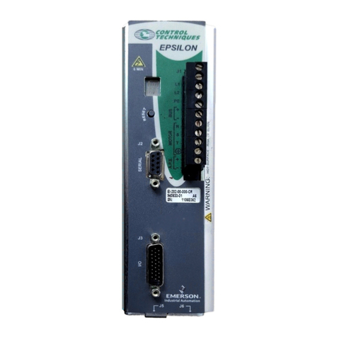
Emerson
Emerson Epsilon Eb Series Reference manual
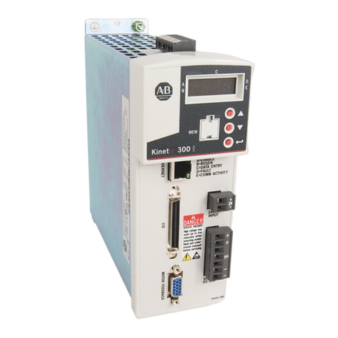
Rockwell Automation
Rockwell Automation Allen-Bradley Kinetix 300 2097-V31PR0 user manual
Emerson
Emerson Unidrive M702 Getting started guide
Baldor
Baldor MotiFlex e100 installation manual

Leadshine
Leadshine EL7-RS Series user manual
YAKO
YAKO ES2 Series user manual
