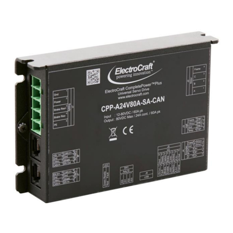
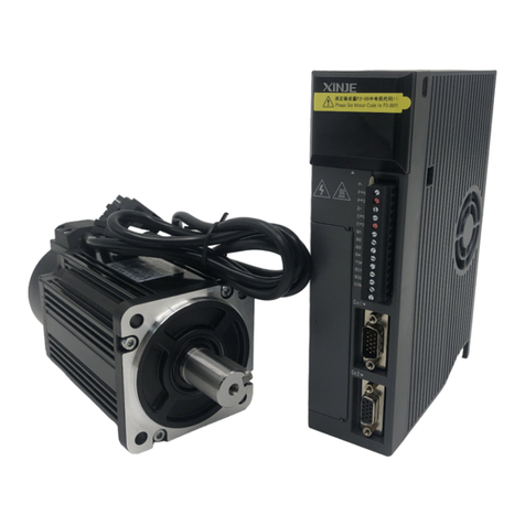
Electro-Craft CompletePower Plus CPP-A12V80A-SA-USB Use and care manual

© ElectroCraft 2018 1 CPP-A12V80A-SA-USB Technical Reference
Record of Revisions:
Revision
Date
Description
Comments
001
2/7/2018
Initial release
Document Released
002
8/15/2018
Phase 2&3 updates
PMDC and Stepper motor
update per ECO_000672
Read This First
While ElectroCraft believes that the information and guidance given in this manual is correct, all parties
must rely upon their own skill and judgment when making use of it. ElectroCraft does not assume any
liability to anyone for any loss or damage caused by any error or omission in the work, whether such error
or omission is the result of negligence or any other cause. Any and all such liability is disclaimed.
All rights reserved. No part or parts of this document may be reproduced or transmitted in any form or by
any means, electrical or mechanical including photocopying, recording or by any information-retrieval
system without permission in writing from ElectroCraft, Inc. The information in this document is subject to
change without notice.
About This Manual
This document is a technical reference manual for CPP-A12V80A-SA-USB hardware. This document
covers the drive hardware including technical data, connectors and wiring diagrams needed for
installation.

© ElectroCraft 2018 2 CPP-A12V80A-SA-USB Technical Reference
If you Need Assistance …
Visit ElectroCraft online
World Wide Web: www.electrocraft.com
If you want to …
• Receive general information or assistance
• Ask questions about product operation or report suspected problems
• Make suggestions or report errors in documentation
Contact ElectroCraft at …
For North America:
Tel
: (844) 338-8114
Email
: drivesupport@electrocraft.com
Mail
: ElectroCraft
2 Marin Way, Suite 3
Stratham, NH 03885-2578
USA
For Outside North America:
Please visit
www.electrocraft.com/contact/

© ElectroCraft 2018 3 CPP-A12V80A-SA-USB Technical Reference
Contents
1Product Safety Precautions ................................................................................... 7
1.1 Operation ...................................................................................................................... 7
1.2 Storage and Transportation........................................................................................... 8
1.3 Environmental Protection .............................................................................................. 8
1.4 Installation..................................................................................................................... 9
1.5 Wiring............................................................................................................................ 9
1.6 Life Support Policy .......................................................................................................10
1.7 Checking Product on Delivery ......................................................................................11
2Product Overview.................................................................................................. 12
2.1 Key Features................................................................................................................12
2.2 Simplified System Block Diagram.................................................................................12
2.3 Hall Sensor Feedback ..................................................................................................13
2.4 Stepper motor Phase Current Waveforms for Different Step values .............................15
2.5 Encoder Feedback .......................................................................................................16
2.6 Motor and Sensor Configurations.................................................................................16
2.7 Identification Labels .....................................................................................................16
2.8 Status Indicator Lights..................................................................................................16
3Drive Specifications .............................................................................................. 17
3.1 Physical Specifications.................................................................................................17
3.2 Environmental Specifications .......................................................................................17
3.3 Electrical Specifications................................................................................................17
3.3.1 DC Supply Input .................................................................................................................... 17
3.3.2 +5VDC Supply Output ........................................................................................................... 17
3.3.3 Motor Output.......................................................................................................................... 17
3.3.4 Hall Sensor Inputs ................................................................................................................. 18
3.3.5 Encoder Inputs ...................................................................................................................... 18
3.3.6 Digital Input............................................................................................................................ 18
3.3.7 Digital Output......................................................................................................................... 18
3.3.8 Analog Input .......................................................................................................................... 18
3.3.9 Analog Output........................................................................................................................ 19
3.3.10 USB Communications ........................................................................................................... 19
3.4 De-rating ......................................................................................................................19
3.5 Peak Current Fold-back (I2t).........................................................................................20
4Hardware Installation ............................................................................................ 21
4.1 Mechanical Mounting ...................................................................................................21
4.2 Dimensions ..................................................................................................................21
4.3 Mating Connectors .......................................................................................................21
4.4 Connector Locations and Pin Numbers ........................................................................22
4.4.1 Connector Layout .................................................................................................................. 22

© ElectroCraft 2018 4 CPP-A12V80A-SA-USB Technical Reference
4.4.2 J1 Supply Connector Pinout.................................................................................................. 22
4.4.3 J2 Motor Connector Pinout.................................................................................................... 22
4.4.4 J3 Hall Connector Pinout....................................................................................................... 22
4.4.5 J4 Encoder Connector Pinout ............................................................................................... 23
4.4.6 J5 I/O Connector Pinout ........................................................................................................ 23
4.4.7 J6 USB Communications Connector Pinout ......................................................................... 23
5Connecting Power................................................................................................. 24
5.1 Power supply ...............................................................................................................24
6Connecting Motors................................................................................................ 25
6.1 Brushless DC Motor .....................................................................................................25
6.2 Permanent Magnet DC (PMDC) Motor.........................................................................25
6.3 Stepper Motor ..............................................................................................................25
7Connecting Motor Feedback Devices.................................................................. 26
7.1 Hall Sensors.................................................................................................................26
7.1.1 Hall Sensor Connections ....................................................................................................... 26
7.1.2 Hall Sensor Signal Input Circuit............................................................................................. 26
7.2 Incremental Encoder ....................................................................................................26
7.2.1 Differential Encoder ............................................................................................................... 26
7.2.2 Single-Ended Encoder .......................................................................................................... 27
7.2.3 Encoder Input Circuit............................................................................................................. 27
7.3 IxR Speed Feedback Estimator....................................................................................27
7.4 Motor Temperature Sensor ..........................................................................................28
7.4.1 Temperature Sensor Connections ........................................................................................ 28
7.4.2 Temperature Sensor Signal Input Circuit .............................................................................. 28
8Connecting I/O....................................................................................................... 29
8.1 I/O Functional Description ............................................................................................29
8.2 Minimum I/O Connections ............................................................................................30
8.2.1 Minimum I/O Connections for BLDC and PMDC motors ...................................................... 30
8.2.2 Minimum I/O Connections for Stepper motor........................................................................ 30
8.3 Digital Inputs and Outputs ............................................................................................31
8.3.1 Digital Input Circuit ................................................................................................................ 31
8.3.2 Digital Output Circuit ............................................................................................................. 31
8.4 Analog Inputs and Outputs...........................................................................................32
8.4.1 Analog Input Circuit ............................................................................................................... 32
8.4.2 Analog Output Circuit ............................................................................................................ 32
9Communication ..................................................................................................... 33
9.1 Connecting USB...........................................................................................................33
10 Introduction to ElectroCraft CompleteArchitect™ PC Software .................... 33
11 First Time Operation .......................................................................................... 33
12 Adding an External Brake Resistor .................................................................. 34
12.1 Caution Statement ....................................................................................................34
12.2 Brake Resistor Theory of Operation ..........................................................................34

© ElectroCraft 2018 5 CPP-A12V80A-SA-USB Technical Reference
12.3 Selecting External Brake Resistor.............................................................................35
12.3.1 Calculating resistance value of the braking resistor.............................................................. 35
12.3.2 Calculating power value of the braking resistor .................................................................... 36
12.4 Minimum external bulk capacitance ..........................................................................37
12.5 Connecting External Brake Resistor and Bulk Capacitor...........................................37
12.6 ElectroCraft Braking Module Assembly .....................................................................38
13 Troubleshooting ................................................................................................. 39
13.1 Status LED (Red)......................................................................................................39
13.2 Power LED (Green) ..................................................................................................40

© ElectroCraft 2018 6 CPP-A12V80A-SA-USB Technical Reference
Table of Figures
FIGURE 1: OVERALL DRIVE SYSTEM BLOCK DIAGRAM...................................................................... 12
FIGURE 2: TRAPEZOIDAL COMMUTATION WITH HALL SENSOR FEEDBACK ................................... 13
FIGURE 3: SINUSOIDAL COMMUTATION WITH HALL SENSOR FEEDBACK ...................................... 14
FIGURE 4: STEPPER MOTOR PHASE CURRENT WAVEFORM ............................................................ 15
FIGURE 5: ENCODER FEEDBACK SIGNAL............................................................................................. 16
FIGURE 6: DRIVE WITH IDENTIFYING LABEL ........................................................................................ 16
FIGURE 7: I2T ALGORITHM EXAMPLE..................................................................................................... 20
FIGURE 8: DRIVE DIMENSIONS............................................................................................................... 21
FIGURE 9: DRIVE CONNECTOR LAYOUT............................................................................................... 22
FIGURE 10: POWER SUPPLY CONNECTION TO THE DRIVE ............................................................... 24
FIGURE 11: BRUSHLESS DC MOTOR CONNECTION TO THE DRIVE ................................................. 25
FIGURE 12: PERMANENT MAGNET DC MOTOR CONNECTION TO THE DRIVE ................................ 25
FIGURE 13: STEPPER MOTOR CONNECTION TO THE DRIVE............................................................. 25
FIGURE 14: HALL SENSOR CONNECTION TO THE DRIVE................................................................... 26
FIGURE 15: HALL SENSOR SIGNAL INPUT CIRCUIT ............................................................................ 26
FIGURE 16: DIFFERENTIAL ENCODER CONNECTION TO THE DRIVE ............................................... 26
FIGURE 17: SINGLE-ENDED ENCODER CONNECTION TO THE DRIVE.............................................. 27
FIGURE 18: ENCODER SIGNAL-ENDED INPUT CIRCUIT...................................................................... 27
FIGURE 19: TEMPERATURE SENSOR CONNECTION TO THE DRIVE ................................................ 28
FIGURE 20: TEMPERATURE SENSOR SIGNAL INPUT CIRCUIT .......................................................... 28
FIGURE 21: MINIMUM DRIVE I/O CONNECTIONS NEEDED TO OPERATE BLDC AND PMDC MOTOR
............................................................................................................................................................. 30
FIGURE 22: MINIMUM DRIVE I/O CONNECTION NEEDED TO OPERATE STEPPER MOTOR ........... 30
FIGURE 23: DIGITAL INPUT CIRCUIT ...................................................................................................... 31
FIGURE 24: DIGITAL OUTPUT CIRCUIT .................................................................................................. 31
FIGURE 25: ANALOG INPUT CIRCUIT ..................................................................................................... 32
FIGURE 26: ANALOG OUTPUT CIRCUIT ................................................................................................. 32
FIGURE 24: USB CABLE CONNECTION BETWEEN COMPUTER AND DRIVE..................................... 33
FIGURE 28: BRAKE RESISTOR OPERATION GRAPH............................................................................ 34
FIGURE 29: EXTERNAL BRAKE RESISTOR AND BULK CAPACITOR CONNECTION TO THE DRIVE
............................................................................................................................................................. 37
FIGURE 30: ELECTROCRAFT BRAKING MODULE................................................................................. 38

© ElectroCraft 2018 7 CPP-A12V80A-SA-USB Technical Reference
1 Product Safety Precautions
READ THIS ENTIRE SECTION BEFORE ATTEMPTING TO USE THE CPP-A12V80A-SA-USB DRIVE!
GIVE SPECIAL ATTENTION TO ALL BOLD PRINT ITEMS.
WARNING!
ElectroCraft products are not authorized for use in safety critical applications. To operate the drive safely,
these minimum precautions MUST be followed to insure proper performance without injury to the operator
and damage to motor or drive. FAILURE TO OBSERVE THESE SAFETY PRECAUTIONS COULD
RESULT IN SERIOUS BODILY INJURY, INCLUDING DEATH IN EXTREME CASES.
1.1 Operation
1. Do not touch any of the connector pins on connectors J1 (Supply Input) or J2 (Motor Output)
when power has been applied. Bare wires from adjacent connector pins must never be allowed to
touch one another.
2. J1 pin 3 must be connected to an external earth ground. Follow wiring procedures carefully.
3. Read ElectroCraft Life Support Policy in section 1.6 for application limitations.
4. Follow precautionary guidelines as referenced in section 12 of this manual with regard to proper
installation of an optional external brake resistor.
5. Do not operate the drive in an explosive area or near explosive or flammable materials.
6. Do not use the drive in environments where it is likely to be exposed to strong and/or frequent
static discharge.
7. Conduct trial operations on the servo drive alone with the motor shaft disconnected from the load
to avoid any unexpected motion. Motor shaft should be uncoupled and free to rotate without
coming in contact with user or any stationary object during set up and preliminary operation.
8. Under no circumstances should a phase output from the control be connected to anything other
than a passive inductive/resistive motor load. Short circuit protection for the drive is limited to
momentary conditions only! Repetitive short circuits on any of the output pins of J2 may cause
permanent damage to the drive.
9. Never touch any moving parts while the motor is running. Failure to observe this warning may
result in injury.
10. Excessive speed and current can destroy some motors and possibly injure the user. Check the
motor manufacturer's specifications to ensure that the maximum current and voltage for your
drive model, does not exceed motor limitations.
11. Whenever the drive is disabled for any reason or unpowered, the motor will be in free
spinning/coast mode. The user is responsible to analyze the application (especially in case of
servomotor for a vertical axis) and take precautionary safety measures.
12. Provide an appropriate stopping device on the machine side to ensure safety. Failure to observe
this warning may result in injury.
13. Do not parallel multiple motors off the same drive.

© ElectroCraft 2018 8 CPP-A12V80A-SA-USB Technical Reference
14. Do not make any extreme adjustments or settings changes of parameters. Failure to observe this
caution may result in injury due to unstable operation.
15. Avoid plugging connector J1 into the drive while live power is applied to the connecting cables.
Ignoring this precaution will cause electrical arcing at the connector pins, which can cause
permanent connector damage. ElectroCraft recommends using a disconnect switch ahead of J1 if
the drive must be disconnected often.
16. Do not remove the connectors on ports J1 through J6 from the drive while the motor is operating.
17. Do not service or modify this product. Only authorized personnel must perform disassembly or
repair of the drive. Failure to observe warning may result in injury or damage to product.
18. Always operate the drive within the prescribed voltage limits. Any attempt to operate outside
these bounds may result in damage to the drive.
19. Safe use of this product depends on factors specific to the end application. These factors are
outside of ElectroCraft knowledge and control. The installer of this servo drive must have a
thorough knowledge of safety precautions and practices relevant to the specific application of this
drive. In particular the installer should consider the risks associated with erroneous or non-
operation of the servo drive in the application and mitigate them appropriately.
1.2 Storage and Transportation
1. Do not store or install the product in the following places:
a. Locations subject to temperature outside of the range specified.
b. Locations subject to humidity outside the range specified.
c. Locations subject to condensation as the result of changes in temperature.
d. Locations subject to corrosive or flammable gases and liquids.
e. Locations subject to dust, salts, or electrically conductive contaminants.
f. Locations subject to exposure to water, oil, or chemicals.
g. Locations subject to shock or vibration.
Failure to observe this caution may result in fire, electric shock, or damage to the product.
2. Do not hold the product by the cables or motor shaft while transporting it. Failure to observe this
caution may result in injury or malfunction.
1.3 Environmental Protection
Waste electrical products should not be disposed of with household waste. Please recycle where facilities
exist. Check with your Local Authority or retailer for recycling.

© ElectroCraft 2018 9 CPP-A12V80A-SA-USB Technical Reference
1.4 Installation
1. Take appropriate and sufficient countermeasures when installing systems in the following
locations.
a. Locations subject to static electricity or other forms of noise.
b. Locations subject to strong electromagnetic fields and magnetic fields.
c. Locations subject to possible exposure to radioactivity.
d. Locations close to power supplies including power lines.
Failure to observe this caution may result in damage to the product.
2. Keep any external shunt/brake resistor away from flammable materials. Read section 12 carefully
for more shunt/brake resistor installation details.
3. Never use this product in an environment subject to liquids, corrosive chemicals or gases; or
combustibles; or where foreign materials can fall onto or collect inside the drive. Failure to
observe this caution may result in electric shock or fire.
4. Do not place any objects on the product. Failure to observe this warning may result in damage to
the product.
5. Do not cover the drive or prevent air from escaping or entering through the vents. Failure to
observe this caution may cause internal elements to deteriorate resulting in malfunction or fire.
6. Provide the specified clearance between the drive and other devices. Provide sufficient space
around the drive for cooling by natural convection or provide cooling fans to prevent excessive
heat. See section 4 for details. Failure to observe this caution may result in fire or malfunction.
1.5 Wiring
1. Verify ALL wiring BEFORE applying power to the drive and motor. Motor may spin or oscillate
uncontrollably if improperly wired. Drive may be damaged or improper wiring may prevent drive
from operation.
2. J1 pin 5, PE, MUST always be connected to an appropriate external Protective Earth ground in
accordance with local electrical codes. Improper grounding may result in electric shock and
damage the drive.
3. Securely connect the power supply terminals and motor output terminals. Failure to observe this
caution may result in fire.
4. Do not bundle or run power and signal lines together in the same duct. Keep power and signal
lines separated.
5. Use twisted-pair shielded wires or multi-core twisted pair shielded wires for signal and encoder
feedback lines.
6. Always use the specified power supply voltage. An incorrect power supply may result in damage
to the drive.

© ElectroCraft 2018 10 CPP-A12V80A-SA-USB Technical Reference
Installation requirements for EMC CE compliance:
For EMC compliance, correct cable selection and wiring practices are mandatory. The following contains
installation instructions necessary for meeting EMC requirements.
•Power interface cable that supply power to the drive should not exceed 3m (9.84ft) in length.
•Motor cables should not exceed 10m (32.8ft) in length without consulting factory. For best results
use Electrocraft series cables.
•Shielded cables are mandatory for the motor, power and control cabling to the drive. The power
and motor cables must be bonded to earth at both ends and the control bonded to earth at one
end. The shield of the cable must be grounded at the closed ground point with the least amount
of resistance.
•Segregate the drive power wiring and motor phase cables from the control wiring and feedback
cabling. When using shielded cables for the power wiring, provide a grounded 360 degree clamp
termination at both ends. Provide for a large contact area between shields and the mounting
plate.
•The J5 I/O port requires an external ferrite located close to the mating connector, with cable
passing once through the ferrite. Fair-Rite – 0431176451 or equivalent is required for compliance.
1.6 Life Support Policy
READ THIS ENTIRE SECTION BEFORE ATTEMPTING TO USE THE CPP-A12V80A-SA-USB DRIVE!
ElectroCraft products are not authorized for use as critical components in life support devices or systems
without the express written approval from ElectroCraft, Incorporated.
1. Life support devices or systems are intended for surgical implant into the body, or support or
sustain life, and whose failure to perform, when properly used in accordance with instructions for
use provided in the User's Manual and in the labeling, can be reasonably expected to result in a
significant injury to the user.
2. A critical component is any component of a life support device or system whose failure to perform
can be reasonably expected to cause the failure of the life support device or system, or to affect
its safety or effectiveness.

© ElectroCraft 2018 11 CPP-A12V80A-SA-USB Technical Reference
1.7 Checking Product on Delivery
When your package arrives, inspect the shipping box and the unit carefully, and save ALL packing
materials. Compare the packing slip against all items included in the shipping box. Any shortages or
other inspection problems should be reported to ElectroCraft immediately.
The following procedure is used to check products upon delivery. Check the following items when your
CPP-A12V80A-SA-USB is delivered.
•Verify that the model number marked on the nameplate of the drive(s) is the correct model
ordered.
•Check the overall appearance. Check for damage or scratches that may have occurred during
shipping.
If any damage is noted, or if the unit is the wrong type, contact your ElectroCraft sales representative
immediately.
Your CPP-A12V80A-SA-USB has arrived carefully packaged from ElectroCraft, in an antistatic bag. As
you unseal this bag, inspect the contents carefully. There should not be any loose or damaged parts
inside.
Never attempt to operate or power-up the drive if there is any visible external damage or if there are loose
materials inside the chassis. While unpacking, if you discover any loose or damaged parts, notify
ElectroCraft within two working days.
ElectroCraft recommends that all packing materials be saved in the event that the drive needs to be
returned.Always place the drive in the same antistatic bag used in the original shipment. Anti-static filler
material should always be placed around the drive so that it cannot shift inside the box. Extreme care
should be exercised when placing packing material around all external connectors to prevent mechanical
stress damage.
All material to be returned to ElectroCraft must have a Return Material Authorization (RMA) tracking
number assigned before shipment. This can be obtained by contacting ElectroCraft. Any product
returned without this number will be rejected by ElectroCraft.
Always insure your shipment for the proper replacement value of its contents. ElectroCraft will not
assume responsibility for any returned goods that have been damaged outside of our factory because of
improper packaging or handling. All goods shipped to ElectroCraft must be shipped FREIGHT PREPAID.

© ElectroCraft 2018 12 CPP-A12V80A-SA-USB Technical Reference
2 Product Overview
This manual describes the installation and operation of the CPP-A12V80A-SA-USB digital servo-amplifier
manufactured by ElectroCraft Inc.
2.1 Key Features
Features of CPP-A12V80A-SA-USB drive:
•+12 to +80 VDC power supply input.
•12 Amps Continuous, 30 Amps Peak (2 seconds).
•2 and 4 quadrant modes.
•Sinusoidal and Trapezoidal commutation modes.
•20 kHz, 40 kHz and 80 kHz of programmable PWM frequency options.
•Current, Speed, Position and Position with Speed modes of operation.
•USB Communication.
•Drive status diagnostics.
•+/-10V Analog command input.
•Digital step and direction input.
•+/-10V Analog output (configurable).
•Encoder mode for low speed performance.
•BLDC, PMDC and Stepper motor control.
•Halls only operation mode for BLDC motor.
•IxR speed feedback estimator mode for PMDC motor.
•Integrated circuit for brake regeneration.
•+/- Travel limit inputs.
•Configurable ramp for current and speed.
•97% efficiency at full load.
•Selectable software protection options.
•Windows®-based set-up and tuning utility software included.
Note: The CPP-A12V80A-SA-USB drive can be configured by the software through USB even when there
is no power supply provided.
2.2 Simplified System Block Diagram
Overall system of CPP-A12V80A-SA-USB is shown in Figure 1. The drive is configured using the
software to operate the motor according to its application.
Drive
Power Supply
I/O
PC Software
Motor
Fee db ack
Figure 1: Overall drive system block diagram

© ElectroCraft 2018 13 CPP-A12V80A-SA-USB Technical Reference
2.3 Hall Sensor Feedback
Drive is capable of operating the BLDC motor using trapezoidal (6-step) commutation with hall sensor
feedback as shown in Figure 2 and sinusoidal commutation with hall sensor feedback as shown in Figure
3.
Motor Phase A
Motor Phase B
Motor Phase C
Hall Sensor 1
Hall Sensor 2
Hall Sensor 3
60° 120° 180° 240° 300° 360° 60° 120° 180° 240° 300° 360°
Figure 2: Trapezoidal Commutation with Hall sensor feedback

© ElectroCraft 2018 14 CPP-A12V80A-SA-USB Technical Reference
Motor Phase A
Motor Phase B
Motor Phase C
Hall Sensor 1
Hall Sensor 2
Hall Sensor 3
60° 120° 180° 240° 300° 360° 60° 120° 180° 240° 300° 360°
Figure 3: Sinusoidal commutation with Hall sensor feedback

© ElectroCraft 2018 15 CPP-A12V80A-SA-USB Technical Reference
2.4 Stepper motor Phase Current Waveforms for Different Step values
The drive is capable of operating the stepper motor in open-loop configuration from full step to 256
microsteps per step at a maximum step rate of 1MHz @ 50% ± 10%. The phase current wave forms for
full step, quarter step and 256 microsteps per step is shown in Figure 4.
30° 60° 90° 120° 150° 180° 210° 240° 270° 300° 330° 360°
0°
Full Step / 1 Microstep per Step
Quarter Step / 4 Microsteps per Step
256 Microsteps per Step
Motor Phase A
Motor Phase B
Motor Phase A
Motor Phase B
Motor Phase A
Motor Phase B
Figure 4: Stepper motor Phase Current Waveform

© ElectroCraft 2018 16 CPP-A12V80A-SA-USB Technical Reference
2.5 Encoder Feedback
Drive counts the encoder lines in a positive direction, when encoder signal A leads encoder signal B by
90° electrical and vice-versa. This function can be reversed using the PC software. Encoder feedback
signal is shown in Figure 5.
Signal A leads B
by 90° Electrical
360°Electrical
Encoder Signal A
Encoder Signal B
Figure 5: Encoder feedback signal
2.6 Motor and Sensor Configurations
Brushless
Motor
PMDC
Motor
Stepper
Motor
Hall Sensors
Yes
No
No
Encoder + Halls
Yes
No
No
Encoder Only
No
Yes
No
IxR Estimator
No
Yes
No
2.7 Identification Labels
Identification label with
ElectroCraft serial number
Figure 6: Drive with identifying label
2.8 Status Indicator Lights
In normal operation, the drive is either in an “Enabled” state or in a “Disabled” state. When power is first
applied, the green LED will be On indicating that power has been applied. The Red LED should be Off,
meaning no errors or faults. The Enable input is used to switch between “Enabled” and “Disabled” states.
Refer to section 13 for LED flash codes and possible causes.

© ElectroCraft 2018 17 CPP-A12V80A-SA-USB Technical Reference
3 Drive Specifications
Using the drive outside the specified absolute maximum ratings will damage the drive. Using the drive
outside normal operating specifications may not guarantee a reliable operation.
3.1 Physical Specifications
Parameter
Conditions
Typical
Units
Weight
Without mating connectors
180
g
Dimensions
Length x Width x Height
(without mating connectors)
109.5 x 85 x 23.33
mm
4.31 x 3.43 x 0.92
Inch
3.2 Environmental Specifications
Parameter
Conditions
Min.
Typical
Max.
Units
Ambient Temperature
Operating Range
0
-
40
°C
Storage Range
-20
-
85
Ambient Humidity
Non-condensing
5
-
95
%RH
3.3 Electrical Specifications
All ratings at ambient temperatures = 0 to 40°C and PWM frequency of 20 kHz, (unless otherwise noted)
3.3.1 DC Supply Input
Parameter
Conditions
Min.
Typical
Max.
Units
Supply Voltage
Operating Range
12
-
80
VDC
Absolute maximum
10.5
-
90
Supply Current
Operating at maximum load and speed
-
12
30
A
Idle condition. No
external connections.
@ 12VDC
-
120
-
mA
@ 80VDC
-
40
-
3.3.2 +5VDC Supply Output
Parameter
Conditions
Min.
Typical
Max.
Units
Output Voltage
Operating Range
5
5.1
5.2
VDC
Output Current
Total combined current on all
connectors
- - 250 mA
3.3.3 Motor Output
Parameter
Conditions
Min.
Typical
Max.
Units
Output Phase Current
Continuous with no additional heatsink
-12
-
12
A*
Peak Current
-30
-
30
Peak Duration maximum
(see I
2
t section 3.5)
-
2
-
s
PWM Frequency
Configured by software
20
-
80
kHz
* Values are peak of Sine

© ElectroCraft 2018 18 CPP-A12V80A-SA-USB Technical Reference
3.3.4 Hall Sensor Inputs
Parameter
Conditions
Min.
Typical
Max.
Units
Input Voltage
Operating Range
0
-
5.5
V
Logic “low” operating
0
-
1
Logic “high” operating
2.3
-
5
Sourcing Current
Logic “low” with internal 2.2K pull up to
+5V
-
-
2.3 mA
3.3.5 Encoder Inputs
Parameter
Conditions
Min.
Typical
Max.
Units
Input Voltage
Single ended
Logic “low” operating
0
-
1
V
Logic “high” operating
2.3
-
5
Differential
(RS422)
High-threshold
-
-
0.1
Low-threshold
-0.1
-
-
Sinking and Sourcing
Current
Single ended
Logic “low”, Sourcing
-
8
-
mA
Logic “high”, Sinking
-
8
-
Input Frequency
Single ended
-
-
4
MHz
Differential
-
-
4
Minimum Pulse Width
Single ended and Differential
125
-
-
nS
Input Impedance
Differential
-
120
-
Ω
3.3.6 Digital Input
Parameter
Conditions
Min.
Typical
Max.
Units
Input Voltage
Logic High
2.3
-
24
V
Logic Low
0
-
1
Absolute maximum
-
-
26
Sinking Current
Operational range when logic High
-
-
5
mA
Sourcing Current
Operational range when logic Low
-
-
33
µA
Input Frequency
Step, Direction
Frequency
-
-
1
MHz
Pulse Width
400
-
-
nS
In 0, Enable,
Brake, Limit +,
Limit -
Frequency
-
-
2
kHz
Pulse Width 200 - - µS
Note: The drive registers a step pulse on the rising edge of the input pulse.
3.3.7 Digital Output
Parameter
Conditions
Min.
Typical
Max.
Units
Output Voltage
Operational range
0
5
24
V
Absolute Max
28
Load impedance
With external pull up to max operational
range voltage
150
-
-
Ω
Absolute Max
112
-
-
3.3.8 Analog Input
Parameter
Conditions
Min.
Typical
Max.
Units
Input Voltage
Operational range
-10
-
10
V
Absolute maximum
-12
-
12
Sinking and Sourcing
Current
At operational range -0.2 - 0.2 mA

© ElectroCraft 2018 19 CPP-A12V80A-SA-USB Technical Reference
3.3.9 Analog Output
Parameter
Conditions
Min.
Typical
Max.
Units
Output Voltage
Operational range
-10
-
10
V
Load impedance
Connected to ground
10
-
-
kΩ
3.3.10 USB Communications
Parameter
Conditions
Type
USB on the drive USB mini type B female
USB 2.0 compatible communications
interface
3.4 De-rating
The drive is protected against overheating. The protection mechanism employed is to shut off current to
the motor when the drive internal temperature reaches the maximum limit. The thermal performance of
the drive is dependent on the application and the environmental conditions. This section provides
guidance for application of the drive within the recommended operating conditions referenced in this
manual. However, thermal performance of the drive is dependent on the specifics of the application and
the environmental conditions.
The drive does not have any temperature or output PWM frequency derating in the ambient temperature
range of 0 to 40°C when mounted according to ElectroCraft recommendations as specified in section 4.1.
Operating the drive outside ElectroCraft recommendations or in a closed box and stagnant air may limit
maximum performance. Use of additional heatsinking or forced air may be required. For applications
outside ElectroCraft recommendations or in ambient temperature outside the limit of 0 to 40°C, please
contact ElectroCraft.
Table of contents
Other Electro-Craft Servo Drive manuals
Popular Servo Drive manuals by other brands
Asco
Asco JOUCOMATIC SENTRONIC 601 Series installation manual
INGENIA
INGENIA Nix series product manual

Emerson
Emerson LX Series user guide
Mitsubishi Electric
Mitsubishi Electric Melservo-J3 Series MR-J3-B manual
Applied Motion Products
Applied Motion Products SV200 DC Hardware manual
Invertek
Invertek optidrive cp2 user guide
Moons'
Moons' SSDC-A Series Hardware manual

Pepperl+Fuchs
Pepperl+Fuchs KCD2-SCD Series manual
Lenze
Lenze 931KPx Communications manual
SSD Parvex
SSD Parvex DIGIVEX Little Drive Servoamplifier User and commissioning manual

Mitsubishi
Mitsubishi MELDAS HS Series Specifications and Instruction Manual
NS system
NS system Tango-B series user manual

