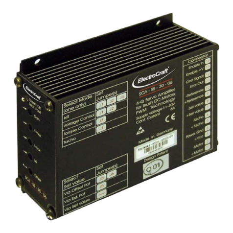
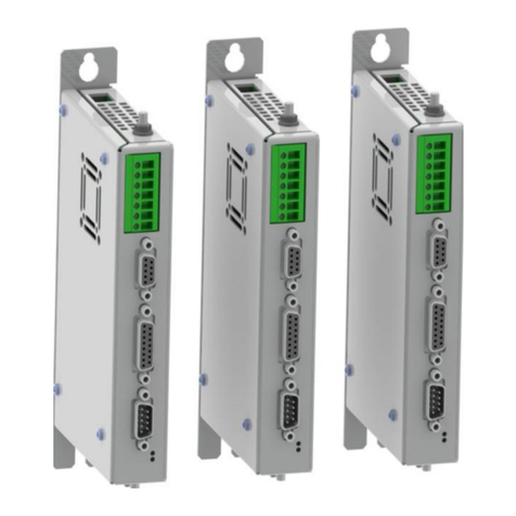
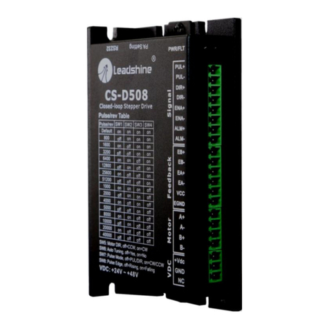
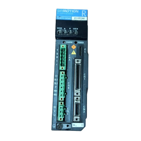
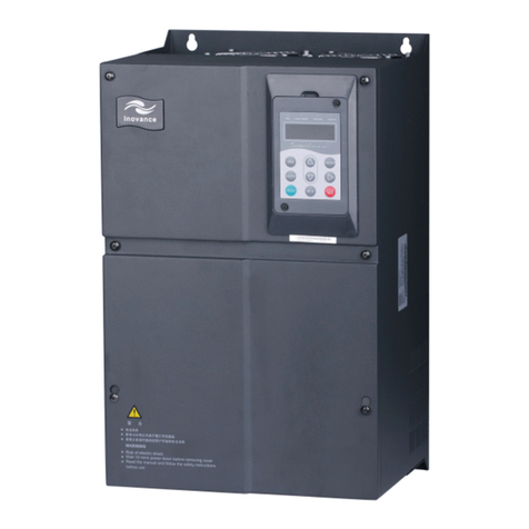
Electro-Craft SCA-LE-30-03 User manual

User Manual SCA-LE-30-03
ElectroCraft®E-Mail: info@electrocraft.com www.electrocraft.com May 2009
1
For Brush-Commutated DC Motors up to 75 W
SCA-LE-30-03
•Servo amplifier in a rugged aluminium housing
•Different methods of mounting for fast installation
•Inputs and outputs via screw terminals
•Operation mode setting with jumpers
•User adjustable current limit
•Wide range supply voltage between +11 and +30 VDC for different kinds of DC-
power supplies
•Protected against overtemperature and over-current
•Linear amplifier
•Continuous current up to 6 A
Basic drive description: The SCA-LE-30-03 servo amplifiers are designed to drive DC
brush type motors. They require a single DC power supply for operation. The drives are to
be used with a single motor. They have the functionality to operate as an independent
speed control or high performance servo. The drives are protected against short circuits,
under voltage, over temperature, and over current. It has multiple modes of operation and
serves as a reliable choice for your motion control needs.
4–Q Linear Servo – 03 A

User Manual SCA-LE-30-03
Table of Contents
1. Safety & Installation.................................................................... 3
2. Specifications:............................................................................. 4
3. Drive Overview ............................................................................ 6
4. Wiring......................................................................................... 10
5. Explanation of Terminals, Dip Switches, & Potentiometers..13
6. Glossary..................................................................................... 17
7. Description of Inputs and Outputs ..........................................24
8. Basic Troubleshooting ............................................................. 28
9. Accessories & Options.............................................................29
10. Warranties & Disclaimers.........................................................30
11. Dimensions................................................................................ 31
12. Mounting Din rail adapter.........................................................32
Used Symbols
Indicates a warning or caution concerning operations that may lead to
death or injury to persons, or damage to property if not performed correctly.
In order to use the drive safely, always pay attention to these warnings.
Indicates a clarification of an operation, or contains additional explanations,
or operational requirements for a procedure. Reading these notes is much
recommended.
ElectroCraft®E-Mail: info@electrocraft.com www.electrocraft.com May 2009
2

User Manual SCA-LE-30-03
ElectroCraft®E-Mail: info@electrocraft.com www.electrocraft.com May 2009
3
1. Safety & Installation
The SCA-LE-30-03 requires installation by qualified personal which must pay
attention to significant safety and other regulatory standards. They should be
thoroughly familiar with the entire system before beginning installation.
Before final operation of machine be sure to test hookup with motor but
disconnected from the load. Improper wiring could cause a “motor run away”
condition, and cause serious injury or damage to the machine and persona
Before starting installation of the SCA-LE-30-03, be sure that main power is
disconnected. After powering the drive it should not be touched by hand or
risk shock.
European directive EN 61800-3 (1996).
nterference with other devices. Damaged items have to be
sitive Device (ESD). Electrostatic
discharge needs to be avoided.
Certain applications may involve special requirements. Consult Factory!
Take care that in case of regeneration or in brake operation the energy
recovery must be buffered by the power supply and / or a braking module.
Ensure with electronically stabilized power supplies that protection circuit isn’t
react.
Don’t switch off the power supply while the motor is turning, in this case the
drive could be destroyed by regeneration.
We recommend connecting a capacitor of 1000 µF per each ampere output
current close to power input, in parallel.
Do not repair or open drives enclosure. Result would result in personal injury
and would void all warranties.
The SCA-LE-30-03 comply with the
The followings points must followed:
•A metal mounting plate with correct grounding is mandatory.
•For installation purposes, tooth lock washers have to be used.
•For most wiring schemes, only shielded cables are admissible, to
suppress i
replaced.
•Provide for a large contact area between shields and mounting plate.
•The motor has to be grounded in the prescribed manner.
•The drive is an Electrostatic Sen
NOTE:

User Manual SCA-LE-30-03
ElectroCraft®E-Mail: info@electrocraft.com www.electrocraft.com May 2009
4
2. Specifications:
2.1 Electrical Data
Power Supply Voltage
+11 to +30 VDC
(Residual ripple <5 %)
(The lower limit is monitored by
integrated undervoltage trip)
WARNING: Do not exceed 70V.
Overvoltage will damage the drive.
Nominal Current 3 A
Maximum Power (only achievable with
additional heatsink & proper mounting,
see accessories.)
75 W
Specification & caution for voltage drop Through the linear output stage the
voltage drop over the drive is depending
of the current and the resistance of the
motor. The highest voltage drop is
caused by a blocked motor. If an
overheating situation occurs in regular
intervals contact factory service for
details.
Power terminals The diameter must be suited for the
current load. The recommendation for
the drive is 1,5 mm2(AWG16), the min.
is 0,14 mm2(AWG26) and the max. is
1,5 mm2(AWG16). Strip the wire
insulation of the cables on a length of
maximal 7 mm. For stranded wire, use
end sleeves with the corresponding
length.
Signal terminals The recommendation is 0,5 mm
2
(AWG21), the min. is 0,14 mm2(AWG26)
and the max. is 1,5 mm2(AWG16). Strip
the wire insulation of the cables on a
length of maximal 7 mm. For stranded
wire, use end sleeves with the
corresponding length.

User Manual SCA-LE-30-03
ElectroCraft®E-Mail: info@electrocraft.com www.electrocraft.com May 2009
5
2.2 Mechanical Data
Mechanical Dimensions L x W x H 121 x 100 x 40 mm
Weight 380 g
Mounting M3 screws or Din Rail Mounting
2.3 Ambient Conditions
Operation Temperature -10 to +45 oC
Storage Temperature -40 to +85 oC
Humidity (Non Condensing) 20 % to 80 % RH
Overtemperature Protection +80 °C
2.4 Digital and Analog Inputs
Enable 8…+30 VDC; Resistance = 5 kOhm
Encoder A, /A, B, /B, I, /I TTL, +5 to +30 VDC;
Resistance > 10 kOhm; max. 600 kHz
-Set value, +Set value Analog -10 – +10 VDC ;
Resistance = 20 kOhm
-Tacho, +Tacho Analog -50 – +50 VDC ;
Resistance = 50 kOhm
24V Opt. In +24 VDC; Resistance = 4,7 kOhm
2.5 Outputs
Auxiliary Voltage Output +Reference +3,9 VDC / 20 mA
Auxiliary Voltage Output -Reference -3,9 VDC / 20 mA
Auxiliary Voltage Output Enable +V 4,7 kOhm to +VCC
Auxiliary Voltage Output +5V +5 VDC / 100 mA
Error out Open Collector / +30 VDC; max. 20 mA
-Tacho out, +Tacho out Analog -3,9 – +3,9 VDC ; max. 20 mA;
Resistance = 100 Ohm
2.6 Control LEDs
OK LED green
The LED is lit when the drive is ready to
work.
Fault LED red
The lamp is lit if the overtemperature, the
undervoltage, the overvoltage or the
overcurrent protection circuit have been
initiated.

User Manual SCA-LE-30-03
3. Drive Overview
3.1 Block Diagram
ElectroCraft®E-Mail: info@electrocraft.com www.electrocraft.com May 2009
6

User Manual SCA-LE-30-03
3.2 Input & Output Schematics
ElectroCraft®E-Mail: info@electrocraft.com www.electrocraft.com May 2009
7

User Manual SCA-LE-30-03
3.3 Control Elements
3.4 Operation Modes
Encoder Mode
At encoder mode feedback information is coming from the encoder signals. The encoder is
mounted at the motor. The speed regulation has got a high performance at each load
condition and qualified for each application to control exactly the speed of a system
especially for low speed application. The maximum achievable speed in this mode is limited
through the encoder input frequency.
Remark:
The modes below are possible with the drive but not advisable. Use in this case the
SCA-LS-30-03. The descriptions and wiring examples for these modes are all
described in the manual of the SCA-LS-30-03.
Voltage Mode
In the voltage mode the drive is watching the output voltage as a feedback voltage. The
drive can not regulate the speed exactly if the motor is loaded with a higher load. This mode
is used e.g. in conveyors with nearly constant load to control the speed.
ElectroCraft®E-Mail: info@electrocraft.com www.electrocraft.com May 2009
8

User Manual SCA-LE-30-03
ElectroCraft®E-Mail: info@electrocraft.com www.electrocraft.com May 2009
9
Tacho Mode
In the tacho mode the feedback information is coming as a voltage signal from a tacho
mounted at the motor. The speed regulation is very good at each load condition and
qualified for each application to control exactly the speed of a system.
IxR Mode
The IxR mode is a voltage mode with an additional factor to correct the speed under
changing the load. The factor which is adjusted with the IxR potentiometer is only an
approximate value. The speed regulation is good but not stable for all load conditions. It is a
compromise between voltage mode and tacho mode.
Torque Mode
In the torque mode the drive does only control the current in the motor. This control loop is
very fast but the speed is moving with the load due to the constant current. This mode is
used in application with force control or as a fast power amplifier for position systems.

User Manual SCA-LE-30-03
4. Wiring
According to the safety directives, a correct cable selection is mandatory. Regular
inspection is advisable. Damaged, burned or kinked items have immediately to be
exchanged.
Power (+Vcc - Power GND)
•Normally no shielding required.
•When connecting several amplifiers to the same supply pack, use star point
wiring.
Motor Wiring (> 30 cm)
•Only shielded cables are recommended.
•Connect the shield to the ground lug of the servo amplifier.
•A separate cable has to be used.
•Choke modules are useful to reduce PWM-pulses.
Connection to encoder (> 30 cm)
•Only shielded cables are recommended.
•Connect the shield to the controller.
•A separate cable has to be used.
Analog Signals (+Set value, -Set value, +Tacho, -Tacho, +Tacho out, -Tacho out)
•In most cases no shielding required. This may be different for low level signals or
in an environment with strong magnetic interference.
•Connect the shield on either end of the cable. For 50/60 Hz interference, remove
the shield on one side.
Digital Signals (Enable In, Error out,)
•No shielding required.
To verify a trouble-free operation and the conformity to CE regulation, it makes only sense
to test the system as a whole, with all components installed (motor, amplifier, supply pack,
EMC filters cables etc.).
Note: To improve the noise immunity, always connect unused logical inputs to a fix
potential.
ElectroCraft®E-Mail: info@electrocraft.com www.electrocraft.com May 2009
10

User Manual SCA-LE-30-03
4.1 Wiring Example I – Encoder Mode
ElectroCraft®E-Mail: info@electrocraft.com www.electrocraft.com May 2009
11

User Manual SCA-LE-30-03
4.1.1 Setting of the Jumpers
Mode Set Value via
Encoder Control
1,5 kHz Offset -
potentiometer external
potentiometer external voltage
Note: Advanced information’s about the jumpers refer chapter 5.3.
4.2.2. Adjustment procedure for Encoder mode
1. Presetting of the jumpers J7 –J12 refer chapter 5.3.
2. Potentiometer pre setting refer chapter 5.2.
3. Choose the maximum set value (e.g. 10 V). Turn the potentiometer n max, until the
desired maximum speed is reached with unloaded motor.
4. Adjust the current limiter to a value requested by you with the I max potentiometer. It
is of major importance that this value is lower than the maximum admissible constant
current (see motor data sheet). To measure the motor current use a current probe in
one of the motor cables with an oscilloscope or a multimeter, or the Monitor I output.
5. Slowly raise the value of the Gain potentiometer. If the motor begins to work
unsteadily, to vibrate or to cause excessive noise, carefully lower the gain factor
again, until the instability symptoms have disappeared for all load selections
6. Set the set value to zero and adjust the Offset potentiometer, to the standstill of the
motor.
WARNING:
Correct connection of the encoder and Tacho out to Tacho is crucial. Otherwise
the motor operates at maximum speed without any control.
ElectroCraft®E-Mail: info@electrocraft.com www.electrocraft.com May 2009
12

User Manual SCA-LE-30-03
5. Explanation of Terminals, Dip Switches, & Potentiometers
5.1 Terminals
Terminal Label Description
XA
Pin 1 & 2 connect to motor.
Pin 3 & 4 connect to power supply.
Pin 5 & 6 input tacho.
Pin 7 & 8 input set value.
Pin 9 voltage output +3,9 VDC.
Pin 10 voltage output -3,9 VDC.
Pin 11 output signal Error out.
Pin 12 signal GND.
Pin 13 voltage output Enable +V.
Pin 14 input Enable In.
Pin 15 & 16 input encoder A, /A.
Pin 17 & 18 input encoder B, /B.
Pin 19 & 20 input encoder I, /I.
Pin 21 GND.
Pin 22 voltage output +5 VDC.
Pin 23 & 24 output tacho.
Pin 25 & 26 connect to power supply.
Pin 27 GND.
Pin 28 voltage input 24V Opt. In.
ElectroCraft®E-Mail: info@electrocraft.com www.electrocraft.com May 2009
13

User Manual SCA-LE-30-03
ElectroCraft®E-Mail: info@electrocraft.com www.electrocraft.com May 2009
14
5.2 Potentiometers
Potentiometer Function Turning to the Left
(ccw) Turning to the Right
(cw)
Gain Gain Factor lowered Factor raised
n max Definition of max. number
of revolutions Value is decreased Value is increased
I max Set value for max. current Upper limit lowered Upper limit raised
IxR IxR offset compensation Low compensation High compensation
Offset Zero Offset (motor stands
still) Motor rotates
counterclockwise Clockwise rotation
Potentiometer setting for start up:
Gain n max I max IxR Offset
Left stop Middle Middle Left stop Middle

User Manual SCA-LE-30-03
5.3 Jumpers
J7 J8 J9 J10 J11 J12 Max. Encoder Input Frequency
Open Set Open Open Open Open 600 kHz
Set Set Open Open Open Open 300 kHz
Open Open Open Open Open Open 150 kHz
Set Open Open Open Open Set 75 kHz
Open Set Set Open Open Set 60 kHz
Set Set Set Set Open Set 30 kHz
Open Open Set Open Open Set 15 kHz
Set Open Set Set Open Set 7,5 kHz
Set Set Set Open Set Set 6 kHz
Set Open Set Open Set Set 1,5 kHz
Refer chapter 7.1.
Remark:
J12 is responsible for the filtering of the output signal. If it is set, the quality of the
Tacho out signal is improved but the dynamic behaviour is reduced due to the
lowpass response.
ElectroCraft®E-Mail: info@electrocraft.com www.electrocraft.com May 2009
15
n max
•
encoder resolution
max. input frequency = —————————————
60

User Manual SCA-LE-30-03
J1 J2 J3 J4 Function Mode
Set Set Open Open Speed Control by Voltage
Set Set Open Set Speed Control by IxR
Open Open Set Open Torque Control
Set Open Open Open Speed Control by Tacho
J5 J6 Methods of entering the set value (refer chapter 7.3)
Open Open External selection using a voltage (0 to 10 VDC) between XA/7 and XA/8.
Set Open External potentiometer is used (0 to 4 VDC).
Set Set The internal Offset potentiometer is used.
Remark:
Do not connect -Set value and +Set value in this case.
ElectroCraft®E-Mail: info@electrocraft.com www.electrocraft.com May 2009
16

User Manual SCA-LE-30-03
ElectroCraft®E-Mail: info@electrocraft.com www.electrocraft.com May 2009
17
6. Glossary
Offset
There are two distinct functions for the Offset-Potentiometer:
1. Levelling the position at which the motor stands still.
2. Selection of the Set Value. This task requires setting jumper J5 and J6. In any
mode, this feature is available and offers the possibility of a quick functional test.
It is advisable to begin the subsequent levelling procedure with an idle run of the motor.
However you cannot expect this calibration to be stable in the long term, because the motor
as well as the controller are always subject to thermal influences.
n max
Use this potentiometer to adapt the desired maximum speed to the amplitude of the present
set value.
Take care not to exceed meaningful limits. An exaggerated value may entail problems for
the control of the servo amplifier, making it impossible e.g. to line-up the system in speed
control operation under load.
Gain
The dynamical behaviour of the servo amplifier must be compatible to the particular
connected motor. The adjusting procedure is performed using the Gain potentiometer. A
bad adaptation (i.e. if the Gain value has been selected too high) can be easily recognized
by excessive motor vibration or noise. Consequential mechanical damages cannot be
excluded, furthermore an overtemperature situation may arise, due to high currents inside
the motor.
When setting the Gain value during a stop, the result most probably will have to be
accommodated one more time, because the dynamical reaction of the motor at a higher
speed will not be sufficient.
Always remember that this potentiometer does not only act on the gain itself, but also on the
frequency of the entire control loop.

User Manual SCA-LE-30-03
I max
The following action requires the motor to be operated with maximum load. The motor
current may be measured e.g. using current probe with effective value display, or by means
of an ammeter located in the motor line.
I max decides on the maximum possible motor current.
The following limits have to be observed:
- Left stop: 5 % of rated current of 3 A
- Right stop: 100 % of rated current + (0 – +10 %)
Note:
Do not overheat the motor. For this reason, the I max limit should always be
selected lower than the maximum admissible constant current.
Encoder mode
This is a closed loop speed mode that receives the speed information from the encoder.
The advantage of a better speed regulation is given especially at lower speed. The encoder
input is proper for encoder with differential or without differential outputs. Connect only the
existing signals of the encoder.
IxR
This potentiometer is helpful to stabilize the speed in a certain range after a change of the
load. First detect the number of revolutions at the lower level, then raise the load and adapt
the speed using the IxR potentiometer.
An optimum precision of the compensation however is not realistic, because the behaviour
of the motor after a load change is only predictable in a certain tolerance.
If the motor current during the alignment procedure starts to oscillate, these disturbances
may be suppressed using the Gain potentiometer.
IxR Mode
The IxR mode is a voltage mode with an additional factor to correct the speed under
changing the load. The speed regulation is good but not stable for all load conditions.
Tacho Mode
In the tacho mode the feedback information is coming as a voltage signal from a tacho
mounted at the motor.
ElectroCraft®E-Mail: info@electrocraft.com www.electrocraft.com May 2009
18

User Manual SCA-LE-30-03
ElectroCraft®E-Mail: info@electrocraft.com www.electrocraft.com May 2009
19
Torque mode
In this mode the driver controls only the current into the motor. The speed of the motor
depends on the load because only the output force of the motor is regulated.
Voltage Mode
In the voltage mode the drive is watching the output voltage as a feedback voltage.
Brushed motor
In brush type motors, commutation is done electromechanically via the brushes and
commutator.
Commutation
Is a term which refers to the action of steering currents or voltages to the proper motor
phases so as to produce optimum motor torque. In brush type motors, commutation is done
electromechanically via the brushes and commutator. In brushless motors, commutation is
done by the switching electronics using rotor position information obtained by Hall sensors.
Analog Position Mode
The analog position mode is using a voltage feedback generated by a potentiometer which
is mounted e.g. on the motor axis.
Back EMF
The voltage generated when a permanent magnet motor is rotated. This voltage is
proportional to motor speed and is present regardless of whether the motor winding(s) are
energized or de-energized.
Brushless motor
A Class of motors that operate using electronic commutation of phase currents, rather than
electromechanical (brush-type) commutation. Brushless motors typically have a permanent
magnet rotor and a wound stator.

User Manual SCA-LE-30-03
ElectroCraft®E-Mail: info@electrocraft.com www.electrocraft.com May 2009
20
Closed loop
This is broadly applied term, relating to any system in which the output is measured and
compared to the input. The output is then adjusted to reach the desired condition. In motion
control, the term typically describes a system utilizing a velocity and/or position transducer
to generate correction signals in relation to desired parameters.
Cogging
A term used to describe non-uniform angular velocity. Cogging appears as jerkiness,
especially at low speeds.
Continuous rated current
The maximum allowable continuous current a motor can handle without exceeding the
motor temperature limits
Continuous stall torque
Is the amount of torque at zero speed, which a motor can continuously deliver without
exceeding its thermal rating. To determined by applying DC current through two windings
with locked rotor, while monitoring temperature. It’s specified with motor windings at
maximum rated temperature and 25 °C ambient temperature, motor mounted to a heat sink.
Refer to individual specs for heat sink size.
Controller
A term describing a functional block containing an amplifier, power supplies, and possibly
position-control electronics for operating a servomotor or step motor.
Demag current
The current level at which the motor magnets will start to be demagnetized. This is an
irreversible effect, which will alter the motor characteristics and degrade performance.
Drive
It‘s an electronic device that controls torque, speed and/or position of an AC or brushless
motor. Typically a feedback device is mounted in or on the motor for closed-loop control of
velocity and position.
This manual suits for next models
1
Table of contents
Other Electro-Craft Servo Drive manuals
Electro-Craft
Electro-Craft CompletePower Plus CPP-A24V80A-SA-CAN User manual

Electro-Craft
Electro-Craft SCA-SE-30-06 User manual

Electro-Craft
Electro-Craft BRU-200 User manual

Electro-Craft
Electro-Craft MAX-430 User manual
Electro-Craft
Electro-Craft CompletePower Plus CPP-A12V80A-SA-USB Use and care manual