manuals.online logo
Brands
  1. Home
  2. •
  3. Brands
  4. •
  5. Electro-Voice
  6. •
  7. Speakers System
  8. •
  9. Electro-Voice TL18-1 User manual

Electro-Voice TL18-1 User manual

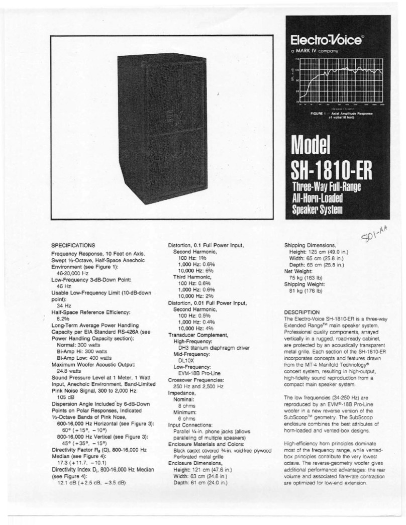
SPECIFICATIONS:
Frequency Response, 1 Watt at 1 Meter
on Axis, Swept One-Third-Octave Pink
Noise, Anechoic Environment (see
Figure 1):
40-3,200 Hz
Low-Frequency 3-dB-Down Point,
Normal:
40 Hz
Step-Down (with equalization):
28 Hz
Usable Low-Frequency Limit
(10-dB-down point),
Normal:
30 Hz
Step-Down (with equalization):
25 Hz
Half-Space Reference Efficiency:
2.9%
Long-Term Average Power-Handling
Capacity per EIA RS-426A (see Power
Handling section):
400 watts
Maximum Long-Term Average Mid-
Band Acoustic Output:
11.6 watts
Sound Pressure Level at 1 Meter, 1
Watt (2.83 volts) Input, Anechoic
Environment, Band-Limited Pink-Noise
Signal,
100-800 Hz:
97 dB
65-125 Hz:
95 dB
Dispersion Angle Included by 6-dB-
Down Points on Polar Responses,
Indicated One-Third-Octave Bands of
Pink Noise (see Figure 3),
50-125 Hz Horizontal and Vertical:
360°
400-800 Hz Horizontal and Vertical:
110° ± 20°
Directivity Factor Rθθ
θθ
θ(Q), Median over
Indicated Range (see Figure 4),
50-125 Hz:
1.0
400-800 Hz:
5.1
Directivity Index Di(10 log Rθθ
θθ
θ),
50-125 Hz:
0.0 dB
400-800 Hz:
7.1 dB
Distortion, 0.1 Full Power Input
(see Figure 5),
Second Harmonic,
100 Hz:
2.0%
1,000 Hz:
2.0%
Third Harmonic,
100 Hz:
0.9%
1,000 Hz:
1.1%
Distortion, 0.01 Full Power Input
(see Figure 6),
Second Harmonic,
100 Hz:
0.7%
1,000 Hz:
0.8%
Third Harmonic,
100 Hz:
0.5%
1,000 Hz:
0.8%
Transducer Complement:
One DL18W-WP
Net Box Volume:
210 liters (7.4 ft3)
Box Tuning Frequency,
Normal:
40 Hz
Step-Down:
28 Hz
Step-Down Peak-Boost Frequency (see
Step-Down section):
29 Hz
Impedance, Nominal/Minimum:
8.0/7.0 ohms
Input Connectors:
Screw terminals (#10) on barrier strip
Enclosure Materials and Finish:
0.7-in. (1.8-cm) black ProWoodTM (see
Description section)
Suspension (see Suspending TL18-1
Enclosures section):
HS1 and HS3 independently certified
hanging kits available
Grille:
Black vibration-resistant steel
Dimensions,
Height:
34.0 in. (86.3 cm)
Width:
24.0 in. (61.0 cm)
Depth:
20.5 in. (52.1 cm)
Net Weight:
41.0 kg (90 lb)
Shipping Weight:
47.0 kg (104 lb)
DESCRIPTION
The Electro-Voice TL18-1 is a member of the TL
series of low-frequency enclosures. The
TL18-1 is a direct-radiating vented design that
provides high efficiency, low distortion and
excellent low-frequency performance in a com-
pact enclosure. The TL18-1 employs a single
DL18W-WP 18-inch loudspeaker, in a 7.4-ft³
TL18-1TL18-1
TL18-1TL18-1
TL18-1
Low-FrLow-Fr
Low-FrLow-Fr
Low-Frequencyequency
equencyequency
equency
Speaker SystemSpeaker System
Speaker System
• The bass pumping ability of an
18-inch woofer and 40-Hz f
3
make
an ideal subwoofer for contemporary
music applications
• 28-Hz f
3
in step-down, ideal for
very-low-frequencysynthesized
effects, down-tuned bass guitars
or pipe organ
• Paintable black vinyl finish
• Optional HS hanging kits—through-
the-box steel tubes allow vertical
suspension of up to three systems
• Indoor and covered outdoor use—
waterproof cones and weather-
resistantProWood
TM
enclosure
SHOWN WITH GRILLE REMOVED
FIGURE 1  Axial Frequency Response
(anechoic environment, 1 watt/1 meter)
FIGURE 2  TL18-1 One-Third-Octave Polar Responses
(anechoic environment)
FIGURE 3  TL18-1 One-Third-Octave Beamwidth vs Frequency
(anechoic environment)
FIGURE 4  TL18-1 One-Third-Octave Directivity vs Frequency
(anechoic environment)
FIGURE 5  TL18-1 Harmonic Distortion,
0.1 Rated Power Input (40 watts), 10 Feet on Axis
FIGURE 6  TL18-1 Harmonic Distortion,
0.01 Rated Power Input (4 watts), 10 Feet on Axis
because it contains many frequencies simulta-
neously, just like real voice or instrument pro-
gram. The signal contains more energy at
extremely high and low frequencies than typi-
cal actual program, adding an extra margin of
reliability. The test combines not only the overall
long-term average or continuous levelwhich
our ear interprets as loudnessbut also short-
duration peaks which are many times higher
than the average, just like actual program. The
long-term average level stresses the speaker
thermally (heat). The instantaneous peaks test
mechanical reliability (cone excursion). Note
that the sine-wave test signals sometimes
used have a much less demanding peak value
relative to their average level. In actual use,
long-term average levels exist from several
seconds on up. We test for several hours,
adding another extra level of reliability.
Specifically, the TL18-1 is designed to with-
stand the power test described in EIA Standard
RS-426A. The EIA test spectrum is applied for
eight hours. The spectrum is obtained by filter-
ing white noise (a particular type of random
noise with equal energy per bandwidth). The
filter applies a 6-dB-per-octave slope below
40 Hz and above 318 Hz. When measured with
a one-third-octave constant-percentage ana-
lyzer, this filter produces a spectrum whose
3-dB-down points are at 100 Hz and 1,200 Hz
with a 3-dB-per-octave slope above 1,200 Hz.
This shaped signal is fed to the power amplifier
with the continuous power set to provide 400
watts into the 6.8-ohm EIA equivalent imped-
ance (48.2 volts rms).
Amplifier clipping sets instantaneous peaks at
6 dB above the continuous power, or 1,200
watts peak (96.4 volts peak). This procedure
provides a rigorous test of both thermal and
mechanical failure modes.
STEP-DOWN
Step-down is a method of extending the low-
frequency response by increasing the power
input to the system instead of the enclosure
volume. In step-down mode, the enclosure is
tuned at a lower-than-normal frequency. This
increases the output at the new tuning fre-
quency and reduces the output at the original
tuning frequency. This smoothly falling ampli-
tude response can be equalized to obtain a
new 3-dB-down point in the region of 0.7 that
of the original. To obtain a similar response
without step-down would require an enclo-
sure with at least twice the volume.
Step-down can be instigated by using the
supplied port cover. Remove the metal grille.
Install the plastic port cover and staple it in
place. Replace the metal grille. The enclosure
tuning will be lowered from 40 to 28 Hz.
If an appropriate low-frequency boost-and-
cut equalization is applied, the normal f3of 40
Hz is reduced to 28 Hz. It is suggested that the
Electro-Voice XEQ-2 or XEQ-3 active cross-
over be used to provide the required equaliza-
tion. The suggested equalization is an
underdamped second-order high-pass filter
tuned to 29 Hz with a Q of 2. This provides a
boost of 6 dB at the tuning frequency and a
12-dB-per-octave roll-off below. This filter is
directly available on the XEQ-2 or can be
generated in the XEQ-3 by using the optional
EB29/35 EQ module.
SUBPASSBAND SPEAKER PROTECTION
Below the enclosure tuning frequency, cone
excursion increases rapidly. Since acoustic
output is also falling rapidly, there is no utility in
driving the system with signals much below
tuning frequency. While such signals may be in
the program material, they are often extrane-
ous, such as a dropped microphone. The step-
down equalization described in the Step-Down
section provides the required protection. If
step-down mode is not used, the Electro-Voice
EX-24, XEQ-2 and XEQ-3 electronic cross-
over/equalizers can also provide subpassband
protection. The 3-dB-down points are 30 Hz
(EX-24 and XEQ-2) and 16 Hz or 32 Hz
(XEQ-3).
Other high-pass filters are available and
1/3-octave equalizers can also be effective at
providing the required protection.
USE IN MULTIPLES
TL systems may be stacked for greater acous-
tic output and a narrower beamwidth.
(It is assumed that all cones are operating in
unison or in phase.)
At relatively low frequencies, below about 150
Hz for typical TL series dimensions, stacking
produces additional acoustic output without
altering dispersion. When a common signal is
applied, a 6-dB increase in maximum acoustic
output occurs. The cones mutually couple
and act as one cone with twice the area
(therefore twice the efficiency) and twice the
power capacity. The additional cone area pro-
vides
3 dB more output and the additional power
capacity accounts for the remaining
3 dB.
Specifically, mutual coupling occurs at fre-
quencies whose wavelengths are longer than
one-quarter the center-to-center distance be-
tween the cones. The highest frequency at
which mutual coupling occurs is calculated
from the following equation:
f ≅3,000 ,
DMAX
where DMAX (inches) is the distance between
the cones, and f (Hz) is the highest frequency
at which coupling occurs. When DMAX is greater
than one-quarter wavelength, which would
occur if two TL18-1s were widely spaced, or
at frequencies much above f even when closely
spaced, the increase in acoustic output is
limited to the 3-dB power-handling increase.
At frequencies above the mutual coupling limit,
f, stacking alters dispersion and increases on-
axis sensitivity. In the 500-to-800-Hz range, a
common crossover frequency for two-way
sound reinforcement systems, two nearly
adjacent cones have a coverage angle about
half that of either cone alone. This is useful, for
example, in more closely matching the typical
40° vertical dispersion of a high-frequency
horn. (At frequencies much above 800 Hz, the
concept of a halved coverage angle no longer
applies, since the side lobes, which result from
enclosure.
The TL18-1s large pumping capability and
40-Hz 3-dB-down point make it appropriate as
a subwoofer for contemporary music play-
back and sound reinforcement. In the step-
down mode, the TL18-1s 28-Hz f3makes it
appropriate for very-low-frequency synthe-
sized effects, down-tuned bass guitars, and
approaches the depths of the symphony or-
chestra and pipe organ. (See Step-Down sec-
tion.)
The enclosure is finished in black with a match-
ing metal grille. Connections are made via
barrier strip (#10) recessed into the back of the
enclosure on a durable molded connector panel.
The enclosure is constructed from ProWoodTM,
a composite structural material which is easily
refinished. ProWood is made of selectively
oriented hardwood strands strongly bonded
together within a phenolic resin matrix. The
surface is a proprietary vinyl laminate, espe-
cially formulated for Electro-Voice, which can
be painted or stained to match any decorative
environment (see Finishing ProWood section).
The TL series is suited for any installation
where high-quality sound is required. The
weather-resistant finish makes these systems
suitable for both indoor and covered outdoor
applications including stadiums, auditoriums
and churches. The enclosures may be stacked
for greater output capability or for a narrower
beamwidth (see Use in Multiples section).
FREQUENCYRESPONSE
The TL18-1s axial frequency response was
measured in Electro-Voices large anechoic
chamber at a distance of 10 feet with a swept
sine-wave input of 4 volts. Figure 1 has been
averaged and corrected for 1 watt/1 meter.
DIRECTIVITY
The directional characteristics of the TL18-1
were measured in Electro-Voices large ane-
choic chamber. The test signal was one-third-
octave filtered pink noise at the frequencies
indicated. A full spherical measurement sys-
tem was used, which is compatible with the
AcoustaCADDTM computer-aided design pro-
gram. All directional information was measured
at 20 feet.
Figure 2 illustrates the horizontal and vertical
polar responses.
Figure 3 shows the horizontal and vertical
beamwidths. Beamwidth is the angle at which
the horizontal and vertical polar responses
have decreased in level by 6 dB when com-
pared to the axial frequency response.
Figure 4 illustrates the total directivity of the
TL18-1. The directivity factor Rθ(Q) is the
relative value, at a point, of the TL18-1
when compared to an ideal spherical response.
The directivity index, Di, is calculated by
Di= 10 log Rθ.
POWER HANDLING CAPACITY
To our knowledge Electro-Voice was the first
U.S. manufacturer to develop and publish a
power test closely related to real-life condi-
tions. A random noise input signal is used
ELECTRO-VOICE a MARK IV company 600 Cecil Street, Buchanan, Michigan 49107
two sources that are not mutually coupled,
increase in number and approach or equal the
main lobe in amplitude. The number of lobes and
their amplitude increases as frequency in-
creases.)
SUSPENDING TL18-1 ENCLOSURES
The TL18-1 has been developed in conjunction
with the HS series of hanging hardware. The
HS kit allows the TL18-1 to be hung safely in a
variety of orientations. The combination of the
correct HS kits and TL18-1 enclosure has been
certified by an independent structural engineer
to be safe and secure. Each HS kit consists of
a steel tube, two brackets, two eyebolts and
the necessary fasteners. The installer must
assemble the HS kit by first drilling two holes
into the TL18-1 enclosure, in predefined posi-
tions, and then screwing the brackets onto the
steel tube, which passes through the enclo-
sure. Full instructions and hole locations are
included with each cabinet and HS kit. A single
TL18-1 requires a single HS3 to suspend it
horizontally, or a single HS1, vertically. How-
ever each cabinet, when hung in multiples,
requires two HS1s horizontally or two HS3s
vertically. A maximum of three cabinets can be
suspended in this manner. Horizontal is defined
by having the central EV logo in its correct
orientation. Full attention must be given to the
instructions and limitations in the HS kit in-
struction sheet.
FINISHING ProWoodTM
Finishing ProWood is simple and straight-
forward as long as a few things are under-
stood:
1. ProWood has been tested with a large
number of commercially available paints
with 100% success. However it is impos-
sible to test every paint available. Electro-
Voice therefore recommends that you test
a small area on the rear of the cabinet or
under the grille to check that there are no
adverse effects.
2. Ensure the surface is clean and free of
grease (use soapy water if necessary).
3. Any latex-, enamel-, or acrylic-based paint
can be used. The special top layer of
ProWood was developed in conjunction
with Pittsburgh Paints. They developed
their Manor Hall®Exterior House series of
paints to complement ProWood.1Electro-
Voice recommends the use of these paints
in adverse or tough situations.
4. Water-based latex paints in particular can
take a considerable time to dry fully. They
can be handled in a few hours but full
strength may not be achieved for a week,
particularly in damp or cool conditions.
5. The paint can be applied with a brush, roller
or spray. Care should be taken not to get
paint on the woofer cone.
6. Stain can be used to highlight the grain in the
ProWood or match real wood. The black
surface must be initially painted a light color.
A good approach is to use a stained var-
nish. Care should be taken when using
stain or stained varnish because it is impos-
sible to lighten a dark staining job without
repainting the enclosure in the light base
color and restaining.
USEOUTDOORS
If the TL18-1 is used outdoors or in adverse
conditions the following applies:
1. Direct rain and sunlight must be avoided.
For example, under the awning in a base-
ball stadium is fine but directly exposed to
the elements on top of the score board is
not.
2. The enclosures should be painted with a
high-quality exterior-grade paint (see Fin-
ishing ProWood section).
3. The enclosure should not, in any circum-
stances, be allowed to stand in water or be
exposed to damp material, such as damp
soil, for any period of time.
ARCHITECTS AND ENGINEERS
SPECIFICATIONS
The loudspeaker system shall be a low-fre-
quency, bass-reflex design. An 18-inch woofer
shall be front mounted in a 7.4-ft3enclosure.
The loudspeaker shall meet the following crite-
ria: power handling, 400 watts of pink noise
with a 6-dB crest factor; frequency response,
smooth and uniform, usable at high output
levels from 40 to 3,200 Hz; sensitivity, 97 dB at
one watt, one meter, 100-800 Hz, on axis;
impedance 8 ohms nominal, 7.0 ohms minimum;
dispersion angles 120° x 120° at 500 Hz. The
enclosure shall be constructed of black
ProWoodTM, a structural hard-wood composite
material with a refinishable external surface.
The enclosure shall be finishable using com-
monly available paints and finishing materials.
The enclosure will contain sound-absorbing
glass wool. An integral black steel grille will be
fitted. A port cover shall be included to enable
step-down operation for enhanced low-fre-
quency performance. The enclosure dimen-
sions shall be 34.0 in. high x 24.0 in. wide x 20.5
in. deep (86.3 cm x 61.0 cm x 52.1 cm). Net
weight shall be
90 lb (41.0 kg). The low-frequency speaker
system shall be the Electro-Voice TL18-1.
WARRANTY (Limited)
Electro-Voice products are guaranteed against
malfunction due to defects in materials or
workmanship for a specified period, as noted
in the individual product-line statement(s) be-
low, or in the individual product data sheet or
owners manual, beginning with the date of
original purchase. If such malfunction occurs
during the specified period, the product will be
repaired or replaced (at our option) without
charge. The product will be returned to the
customer prepaid. Exclusions and Limita-
tions: The Limited Warranty does not apply to:
(a) exterior finish or appearance; (b) certain
specific items described in the individual prod-
uct-line statement(s) below, or in the individual
product data sheet or owners manual; (c)
malfunction resulting from use or operation of
the product other than as specified in the
product data sheet or owners manual; (d)
malfunction resulting from misuse or abuse of
the product; or (e) malfunction occurring at any
time after repairs have been made to the
product by anyone other than Electro-Voice or
any of its authorized service representatives.
Obtaining Warranty Service: To obtain
warranty service, a customer must deliver the
product, prepaid, to Electro-Voice or any of its
authorized service representatives together
with proof of purchase of the product in the
form of a bill of sale or receipted invoice. A list
of authorized service representatives is avail-
able from Electro-Voice at 600 Cecil Street,
Buchanan, MI 49107 (616/695-6831) and/or
Electro-Voice West, at 8234 Doe Avenue,
Visalia, CA 93291 (209/651-7777). Incidental
and Consequential Damages Excluded:
Product repair or replacement and return to the
customer are the only remedies provided to the
customer. Electro-Voice shall not be liable for
any incidental or consequential damages in-
cluding, without limitation, injury to persons or
property or loss of use. Some states do not
allow the exclusion or limitation of incidental or
consequential damages so the above limitation
or exclusion may not apply to you. Other
Rights: This warranty gives you specific legal
rights, and you may also have other rights
which vary from state to state.
Electro-Voice Speakers and Speaker Sys-
tems are guaranteed against malfunction due
to defects in materials or workmanship for a
period of five (5) years from the date of original
purchase. The Limited Warranty does not apply
to burned voice coils or malfunctions such as
cone and/or coil damage resulting from improp-
erly designed enclosures. Electro-Voice ac-
tive electronics associated with the speaker
systems are guaranteed for three (3) years
from the date of original purchase. Additional
details are included in the Uniform Limited
Warranty statement.
Service and repair address for this product:
Electro-Voice, Inc., 600 Cecil Street, Bucha-
nan, Michigan 49107.
Specifications subject to change without no-
tice.
MANUFACTURING PLANTS AT BUCHANAN, MI NEWPORT, TN SEVIERVILLE, TN OKLAHOMA CITY, OK GANANOQUE, ONT.
© Electro-Voice, Inc. 1993 Litho in U.S.A. Part Number 531545  9303
_____________
1. Manor Hall is a registered trademark of Pittsburgh Paints.

Other Electro-Voice Speakers System manuals

Electro-Voice EVR-200 User manual

Electro-Voice

Electro-Voice EVR-200 User manual

Electro-Voice Phoenix PX1152M User manual

Electro-Voice

Electro-Voice Phoenix PX1152M User manual

Electro-Voice XI-1122MHA/64F User manual

Electro-Voice

Electro-Voice XI-1122MHA/64F User manual

Electro-Voice Bass Module Sb122 User manual

Electro-Voice

Electro-Voice Bass Module Sb122 User manual

Electro-Voice Sx80PI User manual

Electro-Voice

Electro-Voice Sx80PI User manual

Electro-Voice E-V Seven-B Dimension Guide

Electro-Voice

Electro-Voice E-V Seven-B Dimension Guide

Electro-Voice TX1122 User manual

Electro-Voice

Electro-Voice TX1122 User manual

Electro-Voice E-V Five-A Dimension Guide

Electro-Voice

Electro-Voice E-V Five-A Dimension Guide

Electro-Voice Skylark User manual

Electro-Voice

Electro-Voice Skylark User manual

Electro-Voice X-Array XF User manual

Electro-Voice

Electro-Voice X-Array XF User manual

Electro-Voice B115-M User manual

Electro-Voice

Electro-Voice B115-M User manual

Electro-Voice T52+ User manual

Electro-Voice

Electro-Voice T52+ User manual

Electro-Voice EVF-1152S/94-FG User manual

Electro-Voice

Electro-Voice EVF-1152S/94-FG User manual

Electro-Voice S1522ER User manual

Electro-Voice

Electro-Voice S1522ER User manual

Electro-Voice TS550D User manual

Electro-Voice

Electro-Voice TS550D User manual

Electro-Voice DeltaMax DMS-1122/85 Series User manual

Electro-Voice

Electro-Voice DeltaMax DMS-1122/85 Series User manual

Electro-Voice 600W Loudspeaker System ZX3-60 User manual

Electro-Voice

Electro-Voice 600W Loudspeaker System ZX3-60 User manual

Electro-Voice FM-1502ER User manual

Electro-Voice

Electro-Voice FM-1502ER User manual

Electro-Voice Force i User manual

Electro-Voice

Electro-Voice Force i User manual

Electro-Voice EVA-2082S/920 User manual

Electro-Voice

Electro-Voice EVA-2082S/920 User manual

Electro-Voice Sx80 User manual

Electro-Voice

Electro-Voice Sx80 User manual

Electro-Voice FRi+ 122/94 User manual

Electro-Voice

Electro-Voice FRi+ 122/94 User manual

Electro-Voice SH15-2 User manual

Electro-Voice

Electro-Voice SH15-2 User manual

Electro-Voice SX Series SX500PI+ User manual

Electro-Voice

Electro-Voice SX Series SX500PI+ User manual

Popular Speakers System manuals by other brands

EAW MK5164 Description

EAW

EAW MK5164 Description

Motorola MOTOROKR EQ7 quick start guide

Motorola

Motorola MOTOROKR EQ7 quick start guide

Ramsa WS-A550-K operating instructions

Ramsa

Ramsa WS-A550-K operating instructions

Hyundai MSD 513 DR instruction manual

Hyundai

Hyundai MSD 513 DR instruction manual

Kenwood KFC-P709PS instruction manual

Kenwood

Kenwood KFC-P709PS instruction manual

Yamaha STAGEPAS 500 owner's manual

Yamaha

Yamaha STAGEPAS 500 owner's manual

LENCO FSP-030 user manual

LENCO

LENCO FSP-030 user manual

Bogen AS1 Installation and use manual

Bogen

Bogen AS1 Installation and use manual

Samsung HW-KM37 user manual

Samsung

Samsung HW-KM37 user manual

DS18 BRO-SBAR/BK owner's manual

DS18

DS18 BRO-SBAR/BK owner's manual

AEG SLS 4705 Instruction manual & guarantee

AEG

AEG SLS 4705 Instruction manual & guarantee

Microlab X13 user manual

Microlab

Microlab X13 user manual

LG SPH4B-W owner's manual

LG

LG SPH4B-W owner's manual

LG LAS464B Simple manual

LG

LG LAS464B Simple manual

LG SK6Y user manual

LG

LG SK6Y user manual

Omnitronic VFM Series user manual

Omnitronic

Omnitronic VFM Series user manual

Canton Smart Soundbox 3 Short manual

Canton

Canton Smart Soundbox 3 Short manual

Yamaha YST-MS55D owner's manual

Yamaha

Yamaha YST-MS55D owner's manual

manuals.online logo
manuals.online logoBrands
  • About & Mission
  • Contact us
  • Privacy Policy
  • Terms and Conditions

Copyright 2025 Manuals.Online. All Rights Reserved.