manuals.online logo
Brands
  1. Home
  2. •
  3. Brands
  4. •
  5. Electro-Voice
  6. •
  7. Speakers System
  8. •
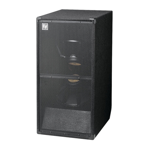
  9. Electro-Voice TL880P Operation manual

Electro-Voice TL880P Operation manual

Electro%ice@
TL880P
Very-Low-Frequency
Powered Speaker
System
.
.
.
.
.
.
.
Digital Capable(TM) designed expressly to meet
the dynamic and low-frequency potential of
digital sound on film
THX approved’
Side-mounted connection panel facilitates
hookup when depth behind the screen is
restricted
Two
EVX-180A
18-inch
woofers, rated at 2,000
watts
of combined continuous program power,
provide
very
high
low-irequency
pumping ability
to
below 23 Hz
Unusually exlended
LF response also appropriate
for very-low-frequency synthesized
effects,
down-
tuned bass guitars or pipe organ
Internal,
P1250
power amp delivers 1,200
watts
continuous to the loudspeakers
On-board P1250 processing provides “step-down”
ED, limiting
to
prevent amp clipping under
high-
output conditions, and infrasonic speaker
protection
‘THX
is a registered trademark of Lucasfilm Ltd.
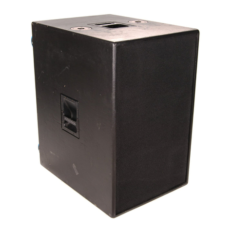
Description and Applications
The Electro-Voice
TL880P
is a member of
the TL series of low-frequency enclosures.
The TL880P is a powered subwoofer de-
signed expressly for digital sound on film
and other applications which require very
high low-frequency pumping ability ex-
tending to 25 Hz and below. The TL880P
features an Electra-Voice
P1250
power am-
plifier, set up in bridge mode driving two
EVX-180A
457-mm
(1
8-in.) speakers, with
a combined rating of 2,000 watts continu-
ous program, connected in parallel. The
P1250
can deliver 1.200 watts continuous
(20-20,000
Hz) to the resultant 4-ohm load.
The
P1250
has on-board signal processing
which supplies:
1. Low-frequency equalization nec-
essary for “step-down” operation
of the loudspeaker system, pro-
viding an overall system response
whose
3-dB-down
point (f,) is 23 Hz.
2. Infrasonic protection of the
EVX-
180A-s
below the
P1250’s
peak boost frequency of 26 Hz.
3. Output limiting that prevents ampli-
fier clipping under high-output con-
ditions.
The side-mounted input for the amplifier
facilitates behind-the-screen installation,
where limited space between the screen and
theatre wall often makes it difficult to con-
nect to the back of an enclosure.
Directivity
In addition to motion-picture applications, the
TL880P
is highly appropriate as the subwoofer
in large,
multiway
systems for contemporary
music playback and sound reinforcement. The
TL88OP
has more output below 40 Hz than the
devices typically used in these applications, in
either the normal (25 Hz) or alternative
(30 Hz) box tuning (see Alternative Vent Tun-
ing and Equalization Options section). Thus.
the
TL880P
is not only appropriate for the
more typical
40-Hz-and-above subwoofer
re-
quirements, but also for those applications,
e.g., very-low-frequency synthesized effects
and down-tuned bass guitars, that require high
output below 40 Hz. This extended low-fre-
quency performance also plumbs the depths
of the symphony orchestra and pipe organ.
The directional characteristics of the
TL88OP
were measured in Electro-Voice’s large
anechoic chamber; the test signal was
one-
third-octave filtered pink noise at the fre-
quencies indicated. A full spherical measure-
ment system was used. All directional informa-
tion was measured at 6.10 meters (20 feet).
Figure 2 illustrates the horizontal and verti-
cal polar responses. Figure 3 shows the hori-
zontal and vertical beamwidths. Beamwidth
is the angle at which the horizontal and ver-
tical polar responses have decreased in level
by 6
dB
when compared to the axial fre-
quency response.
Figure 4 illustrates the total directivity of the
TL880P
The directivity factor R,(Q) is the
ratio of the SPL of the
TL880P
at a given
point to the SPL of an ideal omnidirectional
source at that same point. The directivity
index,
D,,
is calculated by
D,
= 10 log,,, R,.
Frequency Response Power Handling
The
TL88OP’s
axial frequency response was
measured in
Electro-Voice’s
large
anechoic
cham-
ber at a distance of 3.05 meters (10 feet) with a
swept sine-wave input. Figure 1
1
has been aver-
aged and corrected for 1 watt/l meter into the
transducers.
Electro-Voice
components and systems are
manufactured to exacting standards, ensur-
ing they will hold up, not only through the
most rigorous of power tests, but also
through continued use in arduous, real-life
conditions. The eight-hour EIA Loudspeaker
Power Rating Full Range
(ANSI/EIA
RS-
426-A 1980) uses a noise spectrum which
mimics typical music and tests the thermal and
mechanical capabilities of the components.
Electra-Voice will support relevant additional
standards as and when they become avail-
able. Extreme, in-house power tests, which
push the performance boundaries of the woof-
ers, are also performed and passed to ensure
years of trouble-free service.
Specifically, the TL880P passes ANSI/EIA
RS-426-A 1980 with the following values:
R,,
=
4.80 ohms (1.15 x
RJ
P
E(MAX) =
1,200 watts
Test voltage = 75.9 volts rms,
15 1.8 volts peak
The “peak” power-handling capacity of a
woofer is determined by the peak test volt-
age amount. For the
TL880P,
a
151.8-volt
peak test voltage translates into 4,800-watts
short-term peak power-handling capacity.
This is the equivalent of four times the “av-
erage” power-handling capacity, and is a
peak that can be sustained for only a few
milliseconds. However, this sort of
short-
duration peak is very typical in speech and
music. Provided the amplifier can reproduce
the signal accurately, without clipping, the
woofer will also perform accurately and re-
liably, even at these levels.
Continuous program power is defined as 3
dB
above (double) the continuous sine-wave
power rating. The sine-wave power rating is
a two-hour test performed at the minimum
impedance of the system. It is included so
comparisons can be made with competitive
products.
Alternative Vent Tuning and
Equalization Options
The
TL880P
uses the on-board signal pro-
cessing of the
P1250
amplifier to provide
the required equalization for operating in the
“step-down” mode. This equalization reaches
a maximum of 6
dB
at 26 Hz and at 12
dB
per
octave below this frequency (and at 24
dB
per
octave below 15 Hz). Overall system re-
sponse is 3
dB
down (f,) at 23 Hz. (Achiev-
ing this same
fR
without equalization would
require twice the enclosure volume.) The
loudspeaker is shipped with its central port
cover in place to provide the appropriate,
25-Hz box tuning. This configuration must
be maintained for “as shipped” operation of
the
TL88OP.
The step-down mode maximizes
acoustic output ability at frequencies just
below 30 Hz (see Figure
1),
appropriate for
the
TL88OP’s
primary application as a cin-
ema very-low-frequency subwoofer.
If it is not desired to use the
TL88OP
in the
step-down mode, eliminating the need for
boost-and-cut equalization, it is necessary to
remove the central port cover. This moves
box tuning up to 30 Hz and also moves the
system
f3
up to 30 Hz. See the
P1250
Set-
tings section for proper amplifier settings in
the normal mode.
Subpassband Speaker Protection
The
P1250
power amplifier provides
12-dB-
per-octave infrasonic protection of the
EVX-18OA’s
below the
P125O’s
peak-boost
frequency of 26 Hz. Protection is increased
to 24
dB
per octave below 15 Hz.
P1250
Settings
The
TL880P
is shipped with the
P1250
rear-
panel processor settings set for step-down
mode. See Figure 6. The speakers are con-
nected to the central, bridged output. In the
event that the rear-panel settings are dis-
turbed, the proper settings are noted below.
The rear panel of the
P1250
is easily acces-
sible through the access/vent opening in the
speaker enclosure side closest to the top of
the amplifier:
Step-Down Mode Settings (as shipped):
1.
Limiter Time Constant switch: Slow.
2. Processor switch: B6.
3.
Pole Frequency switch: 26.
4.
Bridged Mode switch: Bridged.
5.
Hi-Low-Cut Filter switch: 15.
Normal Mode Settings:
1.
Limiter Time Constant switch: Slow.
2. Processor switch: Off.
3.
Pole Frequency switch: N/A
4.
Bridged Mode switch: Bridged.
5.
Hi-Low-Cut Filter switch: 31 Hz.
Use in Multiples
Cone loudspeakers may be
stacked
for
greater acoustic output and a narrower
beamwidth. (It is assumed that all cones are
operating in unison or “in phase.“) This prin-
ciple is already employed in the dual-woofer
TL88OP,
and is responsible for the higher
sensitivity and narrower vertical beamwidth
(with the system long axis vertical) relative
to similar single-woofer systems. In addi-
tion, two
TL880P’s
can be used side-by-side
and their combined performance will be dif-
ferent from that of a single
TL880P
in the
ways outlined below.
At relatively low frequencies, below about
150 Hz for typical TL series dimensions,
stacking produces additional acoustic out-
put without altering dispersion. When a
common signal is applied, a
6-dB
increase
in maximum acoustic output occurs. The
cones “mutually couple” and act as one cone
with twice the area (therefore twice the effi-
ciency) and twice the power capacity. The
additional cone area provides 3
dB
more
output and the additional power capacity
accounts for the remaining 3
dB.
Specifically, mutual coupling occurs at fre-
quencies whose wavelengths are longer that
one-quarter the center-to-center distance be-
tween the cones. The highest frequency at
which mutual coupling occurs is calculated
from the following equation:
3,000
fG-,
D
MAX
where
D,,,
(inches) is the distance between
the cones, and f (Hz) is the highest frequency
at which coupling occurs. When
D,,,
is
greater than one-quarter wavelength, which
would occur if two
TL880P’s
were widely
spaced, or at frequencies much above f even
when closely spaced, the increase in acous-
tic output is limited to the
3-dB
power-han-
dling increase.
Service
In the unlikely event the
TL88OP
requires ser-
vice, the woofer can be replaced or serviced
from the front and the amplifier can be re-
placed or serviced from the top. A service
data sheet is available from Electro-Voice.
Installation and Suspension of
TL880P
Enclosures
The
TL880P
is designed for typical cinema
stage (behind-the-screen) applications where
subwoofers are mounted on the stage floor.
In addition to the following specific infor-
mation, the user may refer to the P1250
owner’s manual.
The
TL880P
is not designed to he self-sus-
pended from above, and if suspended,
must be supported and hung in a way
which does not depend on the structure
of the
TL880P
itself for support.
Overall System Installation
Precautions
Please read the entire engineering data sheet
before connecting the TL880P to your sys-
tem. For optimum performance, observe the
following precautions:
1.
2.
3.
4.
5.
Keep the ac power switch off while
making connections.
Be certain that connectors are tightly
mated. Loose connections cause hum,
noise or intermittences that could dam-
age your speakers.
Use the proper, high-quality shielded
cables in your entire system. Low-ca-
pacitance cable is preferred.
Turn on the electronic equipment which
feeds the
TL880P
first. Wait eight to
ten seconds, then turn on the P1250
amplifier. This prevents any transient
“pop” which could damage a loud-
speaker
To prevent fire or electrical shock, do
not expose the TL880P to rain or ex-
cess moisture.
Driving Multiple
TL880P’s
The
high,
20,000-ohm
input impedance of
the
P1250
power amplifier allows several
TL880P
systems to be connected in parallel
(daisy chained) to the usual single signal
source, without undesirable loading effects
on the source. Extra connectors on the PI 250
facilitate such daisy chaining.
Signal Input and Polarity Convention
The
P1
250 channel A input connector should
be used. It is easily accessible through the
access/vent opening in the speaker enclosure
side closest to the top of the amplifier. The
connector is a three-pin female connector, pin
2 hot. The
TL880P
does not invert polarity,
i.e., a positive voltage on pin 2 of the Pl250’s
input connector produces a positive (out-
ward) movement of the loudspeaker cones.
This relationship is important under some in-
stallation conditions.
P1250 Input Attenuator Settings
In the factory bridged mono mode, only the
channel A input attenuator is operative.
During system set up, the attenuator should
be set in the full-counterclockwise “off’ po-
sition, in order to avoid inadvertent and pos-
sibly excessive output from the
TL880P.
When the
TL88OP
is first operated under sig-
nal conditions, the attenuator should be ad-
vanced only slightly to check for signal in-
tegrity (the
P1250’s
front-panel channel A
green input LED helps in this regard). Once
proper system operation is confirmed, the
control may be advanced to a point that pro-
vides, in conjunction with the chosen drive
level from upstream equipment, the desired
acoustic output level in the room.
System Physical Orientation and Placement
Any orientation of the
TL880P
is acceptable,
as long as the air flow through the power
amplifier is not impeded. A minimum clear-
ance of 76 mm (3 in.) should be maintained.
Architects’ and Engineers’ Specifications
The loudspeaker system shall be an ampli-
tied, dual-low-frequency, bass-reflex design.
Two
18-inch
woofers shall be front mounted
in a 414-liter
(14.6-cuft)
enclosure. The sys-
tem shall meet the following criteria: The
loudspeaker shall be capable of handling a
total of 1,200 watts long-term average with
a
6-dB
crest factor per ANSI/EIA RS-426-A
1980. The system shall reproduce frequen-
cies to below 23 Hz at a usable level when
used in “step-down” mode with the supplied
port cover in place. The combined sensitiv-
ity of the loudspeakers shall be 98
dB
at one
watt, one meter (100 to 800 Hz). The enclo-
sure shall be constructed of black texture
painted plywood containing sound-absorb-
ing glass wool. The amplifier shall be side
mounted and contain the necessary circuitry
to provide all the equalization and protec-
tion needed to operate the system in step
down mode. The system, with minor modifi-
cation, can be used as a conventional vented
box and amplifier. The enclosure dimensions
shall be 1.21m x 0.76m x 0.60m (47.5 in. x
30 in. x 23.8 in.) (hwd) Net weight shall be
89.6 kg (197.5 lb)
The very-low-frequency system shall be the
Electro-Voice
TL880P
Uniform Limited Warranty
Electro-Voice products are guaranteed
against malfunction due to defects in mate-
rials or workmanship for a specified period,
as noted in the individual product-line
statement(s) below, or in the individual prod-
uct data sheet or owner’s manual, beginning
with the date of original purchase. If such
malfunction occurs during the specified pe-
riod, the product will be repaired or replaced
(at our option) without charge. The product
will be returned to the customer prepaid.
Exclusions and Limitations:
The Limited
Warranty does not apply to: (a) exterior fin-
ish or appearance; (b) certain specific items
described in the individual product-line
statement(s) below, or in the individual prod-
uct data sheet or owner’s manual; (c) mal-
function resulting from use or operation of
the product other than as specified in the
product data sheet or owner’s manual; (d)
malfunction resulting from misuse or abuse
of the product; or(e) malfunction occurring
at any time after repairs have been made to
the product by anyone other than Electro-
Voice Service or any of its authorized ser-
vice representatives.
Obtaining Warranty
Service:
To obtain warranty service, a cus-
tomer must deliver the product, prepaid. to
Electro-Voice Service or any of its autho-
rized service representatives together with
proof of purchase of the product in the form
of a bill of sale or receipted invoice. A list
of authorized service representatives is avail-
able from Electro-Voice Service at 600
Cecil Street, Buchanan, MI 49107 (800-234-
6831 or 616-695-6831).
Incidental
and Consequential Damages Excluded:
Product repair or replacement and return to
the customer are the only remedies provided
to the customer. Electro-Voice shall not be
liable for any incidental or consequential
damages including, without limitation, in-
jury to persons or property or loss of use.
Some states do not allow the exclusion
or limitation of incidental or consequen-
tial damages so the above limitation or
exclusion may not apply to you. Other
Rights:
This warranty gives you specific
legal rights, and you may also have other
rights which vary from state to state.
Electro-Voice Speakers and Speaker
Systems
are guaranteed against malfunc-
tion due to defects in materials or work-
manship for a period of five (5) years from
the date of original purchase. The Lim-
ited Warranty does not apply to burned
voice coils or malfunctions such as cone
and/or coil damage resulting from im-
properly designed enclosures. Electro-
Voice active electronics associated with
the speaker systems are guaranteed for
three (3) years from the date of original
purchase. Additional details are included
in the Uniform Limited Warranty state-
ment.
Electro-Voice Electronics
are guaran-
teed against malfunction
due
to defects
in materials or workmanship for a period
of three (3) years from the date of origi-
nal purchase. Additional details are in-
cluded in the Uniform Limited Warranty
statement.
Electro-Voice Accessories
are guar-
anteed against malfunction due to de-
fects in materials or workmanship for
a period of one (1) year from the date
of original purchase. Additional details
are included in the Uniform Limited
Warranty statement.
Electro-Voice Flying Hardware
(in-
cluding enclosure-mounted hardware and
rigging accessories) is guaranteed against
malfunction due to defects in materials
or workmanship for a period of one (1)
year from the date of original purchase.
Additional details are included in the
Uniform Limited Warranty statement.
Figure
1- TL88OP
Axial Frequency
Response 1 watt/l meter into
transducer
“Alternate Tuning”
no vent cover
“Normal Tuning”
with built in EQ
----
Figure 2-TL880P Polars
I
Horizontal
V
110.
100
Hz125 Hz
110
100
I
zoo
d
m
80
70
111111
I I
I1111111
I I
I
I111111
II
m
*
Y
I”
m
u
II
mm
u
1**
)**
160
Hz
1111.
200
Hz
Figure
3-TL880P
Beamwidth
VS
.
Frequency
1. Woofers Horizontal
Figure
4-TL880P
Directivity vs.
Frequency
Figure S-TL880P 10% Power
Harmonic Distortion Step-Down with
EQ
Figure
6-TL88OP
Amp Settings for
Step-Down Operation (as shipped)
300
300
200
100
80
60
40
30
20
20
30
50
100
200 500
1000
2000
FREQUENCY(Hz)
FREQUENCY(k)
P1250
Amplifier Settings
,5
3,Hz
LIMITER TIME
coNsTAM
Jp4$pHZ
Ems&D
“,gay
5r!
PRCCE-
POLE
-iILlER
FREQMNCY
IF2
FAST
SLiM
BRIDGED
NORMAL
The
settings
above
require the
vent
cover
to
be in
place
(as
delivered)
for proper and
safe
operation of the
system.
System Specifications
Typical Axial Frequency Response
(swept sine-wave input, 10 feet,
anechoic
environment, normalized
for 1 watt, 1 meter into speakers;
see Figure 1):
23-
1,800 Hz
Low-Frequency 3-dB-Down Point,
Normal Tuning (vent cover
instaIled
for
step-down mode, with equalization):
23
Hz
Alternate
Tuning
(vent cover
removed, no equalization):
30
Hz
Usable Low-Frequency Limit
(10-dB
down point),
Normal
Tuning
(vent cover
installed
for
step-down
mode
with equalization):
20
Hz
Normal Tuning (vent cover installed for
step-down
mode, no equalization):
18Hz
Alternate Tuning (vent cover
removed, no equalization):
27 Hz
Sound Pressure Level at 1 Meter,
Maximum Gain and Amplifier at
Clipping Threshold, 0 dBu (0.775 volts
rms) into Balanced Input, Anechoic
Environment, Swept Sine Wave,
l00-
to
800-Hz
Average:
129
dB
50-
to
125-Hz
Average:
127
dB
Half-Space Reference Efficiency
(transducers):
6.0%
Maximum Long-Term Average
Mid-
Band Acoustic Output:
72 watts
Dispersion Angle Included by 6-dB-
Down Points on Polar Responses
(see Figure 3):
Essentially omnidirectional
in
subwoofer range, more directive above
System Distortion, 0.1
Full
Power Output,
Second Harmonic (see Figure
5),
100 Hz:
0.9%
Third Harmonic,
100 Hz:
0.4%
Transducer Complement:
Two EVX-180A
Transducer Impedance (nominal/
minimum):
4.0/4.2
ohms
Net Box Volume:
414 liters (14.6
ft3)
Box
Tuning
Frequency,
Normal fining (vent cover installed
for step-down mode):
26
Hz (as shipped)
Alternate
Tuning
(vent cover removed):
30 Hz
Step-Down Peak-Boost Frequency (see
Alternative Vent Tuning and Equaliza-
tion Options section):
26
Hz (as shipped)
Hi-Low-Cut Filter,
Frequency:
15 Hz (as shipped)
Slope:
12
dB
(as shipped)
Enclosure Materials and Colors:
Black texture-painted poplar plywood
Amplifier
Safety Approvals (in procedure):
UL-8
13;
CSA-C22.2; IEC-65
(ENG-0065); EMC
Directive for
European
RFI/EMI
emissions
Dimensions,
Height:
1.21 m (47.5
in.)
Width:
762
mm (30.0 in.)
Depth:
605
mm (23.8 in.)
Net Weight:
89.6 kg (197.5 lb)
Shipping Weight:
97.6 kg (215.3
lb)
Amplifier (see
P1250
documentation for
full specification)
System Output Power, Continuous
4-ohm
load, bridged,
l00-
to
130-volt
ac line
voltage):
1,200 watts
Power Bandwidth as Used in Bridged
Mode (+0 to -1 dB, reference 1
kHz):
20-20,000
Hz
Frequency Response (-1 dB, reference
1
kHz/l
watt):
10-30,000
Hz
Total Harmonic Distortion Plus Noise at
1
kHz
(at rated power, measurement
bandwidth 80
kHz):
<O.Ol%
Input,
Type:
True balanced, electronic
Connector:
3-pin
female XLR-type connector wired
according to the IEC 268 standard: pin 1
shield, pin 2 positive, pin 3 negative
Polarity (for positive sound pressure):
Pin 2 positive
Sensitivity (for
1,200-watt,
unclipped output), System Gain
Control Full Clockwise:
0
dBu (0.775 volts)
Impedance:
20 kilohms
Controls and Switches, Rear (see Figure 6
and
P1250
Settings section for default
settings):
Limiter time constant; processor; pole
frequency; bridged
mode switch;
hi-lo-
cut filter; input routing, parallel or dual;
circuit-to-chassis switch, parallel or dual
Front:
Power on-off switch; indicator LED’s;
two calibrated input level controls
Power Consumption (both channels
operating in dual mode, 1/8 power),
4 Ohms:
660
VA
Input Voltage:
120
V,
50-60 Hz ac
Tolerance of mains voltage:
&
10%
ac Line Cord:
l4-gauge,
three-wire, permanently
attached
power cable
Electro%ice”
600 CecilStreet, Buchanan, MI 49107
SPEAKERS-Low-FrequencySystems
800/234-6831,
616/695-6831,
Part Number 53343 1-9623

Other Electro-Voice Speakers System manuals

Electro-Voice FRi+ 122/94 User manual

Electro-Voice

Electro-Voice FRi+ 122/94 User manual

Electro-Voice Sound Reinforcement System Xi-1123A/106F User manual

Electro-Voice

Electro-Voice Sound Reinforcement System Xi-1123A/106F User manual

Electro-Voice X-Line Xvls User manual

Electro-Voice

Electro-Voice X-Line Xvls User manual

Electro-Voice Phoenix PX2122 User manual

Electro-Voice

Electro-Voice Phoenix PX2122 User manual

Electro-Voice Supercaster Supercaster High Power Speaker... Dimension Guide

Electro-Voice

Electro-Voice Supercaster Supercaster High Power Speaker... Dimension Guide

Electro-Voice SH15-2 User manual

Electro-Voice

Electro-Voice SH15-2 User manual

Electro-Voice Stereon Control XX3 User manual

Electro-Voice

Electro-Voice Stereon Control XX3 User manual

Electro-Voice MTH-1 User manual

Electro-Voice

Electro-Voice MTH-1 User manual

Electro-Voice EVF-1152S/94 User manual

Electro-Voice

Electro-Voice EVF-1152S/94 User manual

Electro-Voice TX1152 User manual

Electro-Voice

Electro-Voice TX1152 User manual

Electro-Voice E-V FOURTEEN Dimension Guide

Electro-Voice

Electro-Voice E-V FOURTEEN Dimension Guide

Electro-Voice FRi-2082 User manual

Electro-Voice

Electro-Voice FRi-2082 User manual

Electro-Voice T351 User manual

Electro-Voice

Electro-Voice T351 User manual

Electro-Voice FRX+640 User manual

Electro-Voice

Electro-Voice FRX+640 User manual

Electro-Voice Manifold Technology MTH 2.5/42BT User manual

Electro-Voice

Electro-Voice Manifold Technology MTH 2.5/42BT User manual

Electro-Voice Baronet Dimension Guide

Electro-Voice

Electro-Voice Baronet Dimension Guide

Electro-Voice 600W Loudspeaker System ZX3-60 User manual

Electro-Voice

Electro-Voice 600W Loudspeaker System ZX3-60 User manual

Electro-Voice Theatre Stage System TS940D User manual

Electro-Voice

Electro-Voice Theatre Stage System TS940D User manual

Electro-Voice X-Array Install Xi-1122-85 User manual

Electro-Voice

Electro-Voice X-Array Install Xi-1122-85 User manual

Electro-Voice SX Series SX500PI+ User manual

Electro-Voice

Electro-Voice SX Series SX500PI+ User manual

Electro-Voice TL12-1 User manual

Electro-Voice

Electro-Voice TL12-1 User manual

Electro-Voice DeltaMax DMS-1122/85 Series User manual

Electro-Voice

Electro-Voice DeltaMax DMS-1122/85 Series User manual

Electro-Voice TS550D User manual

Electro-Voice

Electro-Voice TS550D User manual

Electro-Voice FRi+ 152/64 User manual

Electro-Voice

Electro-Voice FRi+ 152/64 User manual

Popular Speakers System manuals by other brands

Yamaha NS-C8800 user guide

Yamaha

Yamaha NS-C8800 user guide

Microlab FC730 user manual

Microlab

Microlab FC730 user manual

Panasonic RXDT770 - RADIO CASSETTE W/CD operating instructions

Panasonic

Panasonic RXDT770 - RADIO CASSETTE W/CD operating instructions

TCL Alto 7 user manual

TCL

TCL Alto 7 user manual

HK Audio CONTOUR ARRAY manual

HK Audio

HK Audio CONTOUR ARRAY manual

JVC CA-MXG950V instructions

JVC

JVC CA-MXG950V instructions

Sven HT 425 Operation manual

Sven

Sven HT 425 Operation manual

Kenwood KS-8200EX instruction manual

Kenwood

Kenwood KS-8200EX instruction manual

Philips Fidelio HTL9100 user manual

Philips

Philips Fidelio HTL9100 user manual

LG SP9YA Simple manual

LG

LG SP9YA Simple manual

iLive ITB382B user guide

iLive

iLive ITB382B user guide

Pioneer XW-NAC3-K operating instructions

Pioneer

Pioneer XW-NAC3-K operating instructions

Bowers & Wilkins 600 Series 3 manual

Bowers & Wilkins

Bowers & Wilkins 600 Series 3 manual

Samsung HW-J250/ZA user manual

Samsung

Samsung HW-J250/ZA user manual

Boss Audio Systems Rebel MC300 user manual

Boss Audio Systems

Boss Audio Systems Rebel MC300 user manual

Infinity TSS-500OM owner's guide

Infinity

Infinity TSS-500OM owner's guide

Wahsega Labs WL-SPKR-22-INF-1 installation guide

Wahsega Labs

Wahsega Labs WL-SPKR-22-INF-1 installation guide

Omnitronic BX-series user manual

Omnitronic

Omnitronic BX-series user manual

manuals.online logo
manuals.online logoBrands
  • About & Mission
  • Contact us
  • Privacy Policy
  • Terms and Conditions

Copyright 2025 Manuals.Online. All Rights Reserved.