manuals.online logo
Brands
  1. Home
  2. •
  3. Brands
  4. •
  5. Electro-Voice
  6. •
  7. Speakers System
  8. •
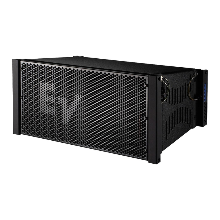
  9. Electro-Voice X-Array Install Xi-2123/106 User manual

Electro-Voice X-Array Install Xi-2123/106 User manual

Description
Introducing a family of advanced sound
reinforcement products for everyone who
desires the sound quality of Electro-Voice's
X-Array™ touring systems. X-Array In-
stall™ is the ideal choice for small-to-me-
dium array configurations and fixed instal-
lations of any size.
Inspired by the most demanded features
of EV's acclaimed X-Array™ touring sys-
tems, the X-Array Install™ series incorpo-
rates a potent combination of very high
output, medium- to long-throw "cells," and
Ring-Mode Decoupling (RMD™). The Xi-
2123/106 is the first in a series of compact,
low- to medium-throw enclosures with op-
timized directivity for a wide range of ap-
plications.
Ring-Mode Decoupling (RMD™)
RMD™ (Ring-Mode Decoupling) is the
same advanced technology built into the
X-Array™ touring series. RMD™ pro-
duces substantially improved tonal char-
acter and fidelity whether operated at low
or extremely high sound pressure levels.
RMD™ attacks time domain "ringing
modes" at their sources. Mechanical solu-
tions resolve mechanical issues, and
acoustical solutions address acoustical
modes found in all sound reinforcement
systems. The combination of each RMD™
technique provides improved tonal char-
acter and fidelity at increasing drive lev-
els. The result is clear, even sound quality
with vastly improved intelligibility.
Xi-2123/106 and Three-Element Line Array
These triamp-ready, three-way systems in
a unique three-element-line-array configu-
ration are designed for use in reverberant
spaces. Dual spaced woofers flank and work
with the central mid-bass horn to form the
line array, extending vertical directivity con-
trol to below 160 Hz. Such wide-bandwidth
control and the low-Q (100° x 60°) pattern
provides superior direct-to-reflected SPL
ratios and improved system intelligibility,
and suppress feedback below arrays.
When optimum directivity control is re-
quired, the Xi-2123/106 with dual 12-inch
woofers should be used. The 10-inch mid-
bass driver features RMD™ and is coupled
to a rotatable 100° x 60° vertical horn.
The high-frequency system uses a DH6
large-format compression driver with a ro-
tatable 100° x 60° horn. It is mounted within
the upper woofer manifold to provide a
compact vertical size. For extended-bass/
subbass, the Xi-2123/106 may be used with
the Xi-1191 or Xi-2181 subwoofers.
Applications
The Xi-2123/106 is ideally suited for high-
level, high-fidelity applications. The sys-
tem is particularly suited where extended
vertical polar control is necessary. The
extended capabilities of the system, par-
ticularly the low-frequency capability, al-
low the system to be used in many appli-
cations without a subwoofer. For applica-
tions requiring very high low-frequency
sound pressure levels as well as very accu-
ratevocalreproduction,theXi-2123/106may
be coupled with the Electro-Voice Xi-
1191 or Xi-2181. The combined system
should be run with a conventional
subwoofer crosssover implementation
(sub crossover to Xi-2123/106 at 80 Hz).
Power-Handling Test
Electro-Voice components and systems are
manufactured to exacting standards to en-
sure reliability in continuous use in arduous
real-life conditions. Besides utilizing indus-
try-standard power tests, extreme in-house
Xi-2123/106
X-Array Install™
Three-Way, Three-Element
Line Array, Full-Range,
Sound-Reinforcement System
• Full Ring-Mode Decoupling (RMD™)
• Three-Element-Line-Array configured
vertical control below 160 Hz
• Ultra-compact/high-level, three-way
design
• 2 12-inch low-frequency drivers with
improved internal damping
• New design, 10-inch mid-bass driver
(100° x 60°)
• New
100° x 60°
HF section includes DH6
compression driver for very high output,
extremely rigid piston range performance
• Fully rotatable MB and HF section for
vertical or horizontal suspension
X-Array InstallTM Xi-2123/106 Loudspeaker System
X-Array Install
TM
Xi-2123/106 Loudspeaker System
2
power tests which push the performance
boundaries of the loudspeakers are also
performed for an extra measure of reliabil-
ity. The Xi-2123/106 systems are rated per
ANSI/EIA RS426-A 1980 Loudspeaker
Power Rating, Full Range Test, which uses
a shaped-random-noise signal to simulate
typical music to test the mechanical and
thermal capabilities of the loudspeakers.
The DN8000 digital electronic unit was
used to provide the necessary crossover
filters and equalization during power test-
ing. Specifically, the Xi-2123/106 passes the
ANSI/EIA RS426-A power test with the
following test parameters:
Low-FrequencySection:
PE(MAX): 600 watts
Test Voltages: 47.0 volts rms
94.0 volts peak
RSR(1.15RE): 3.68 ohms
Mid-bass Section:
PE(MAX): 300 watts
Test Voltages: 45.5 volts rms
91 volts peak
RSR(1.15RE): 6.9 ohms
High-Frequency Section:
PE(MAX): 75 watts
Test Voltages: 30.1 volts rms
60.2 volts peak
RSR(1.15RE): 12.1 ohms
Biamplifying, Crossover, Equalization
And Time-Delay Controller
The Xi-2123/106 speaker system and vari-
ants are designed as an integrated pack-
age that utilizes the Merlin ISP-100, Klark
TeknikDN8000orElectro-VoiceDx34Adigi-
tal crossover system. Optimal performance
of the Xi-2123/106 speaker system can only
be assured when using the above control-
lers. The systems may be biamplified by
removing the input panel and switching a
6-pin molex connector. Separate presets
are available for the biamplified mode.
Electrical Connection And System
Wiring
Electrical connections to the Xi-2123/106
are made on the back of the enclosure via
an 8-pin connector. There are two connec-
tors on the input panel to allow paralleling
of other Xi-2123/106 systems. The Neutrik
Speakon® NL8MPR is used for both con-
nections. The pin assignments are as fol-
lows:
HF: Pin 4 In / Pins 4 Out
MB: Pin 3 In / Pins 3 Out
LF: Pin 1 In / Pins 2 Out
The wiring diagram of the loudspeaker sys-
tem is shown in figure 7. The electrical im-
pedance is shown in Figure 6.
AmplifierRecommendations
Power amplifiers with the following rat-
ings are recommended for use with the
Xi-2123/106 speaker systems:
LF: 600 watts per channel into 8 ohms.
MB: 600 watts per channel into 8 ohms.
HF: 600 watts per channel into 8 ohms.
Xi-2123/106 speakers may be paralleled
only with other Xi-2123/106 speakers if the
amplifier is capable of delivering full power
at the lower impedances. The use of am-
plifiers with lower power ratings is accept-
able; however, the full-power capabilities
of the Xi speakers will not be realized. The
use of amplifiers with significantly higher
power ratings will generate maximum dy-
namic range and fidelity, but care must be
utilized for longer duration signals as me-
chanical and thermal damage is possible in
the system.
Flying the Xi Systems
A manual entitled the X-Array Install™
Flying Manual is available from Electro-
Voice, and is included with each flying Xi
loudspeaker system. A brief introductory
overview is included here. The X-Array In-
stall™ Flying Manual should be con-
sulted for complete structural specifications
and detailed information on safely sus-
pending and using the Xi systems.
The Xi systems incorporate a unique two-
pointflying system thatpermits a widerange
ofvertical angle adjustment, andoffersmaxi-
mumflexibility in arraydesign for bothtour-
ing sound and permanent installations. The
quick-release, aircraft-rated heavy-duty L-
track-type hardware design allows arrays of
loudspeakers to be assembled (and disas-
sembled) very quickly, and offers such flex-
ibility in the vertical angling of cabinets
that pull-up points are usually unneces-
sary. Furthermore, all of the flying Xi loud-
speaker models include the same rigging
hardware, allowing different models to be
mixed as necessary throughout an array.
The working-load limit (for an 8:1 safety
factor) for each rigging point on the Xi loud-
speaker enclosure is 227 kg (500 lb) for a 0°
pull angle and 170 kg (375 lb) for a 90° pull
angle when used with the New Haven
NH32101-2 double-stud fitting, and 113 kg
(250 lb) at any angle when used with the
New Haven NH8192-2S or Ancra 42546-10
single-stud fittings with locking pins. The
working-load limit (for an 8:1 safety fac-
tor) for the overall enclosure is 340 kg
(750 lb). (Consult the X-Array Install™
Flying Manual for specific structural rat-
ings and limitations.) The enclosures may
be oriented with the rigging track on the
sides of the enclosure, or on the top and
bottom, and may be daisy-chained together
as long as the safety factor is 8:1 or greater,
and local regulations are met. For fire safety
and additional structural strength in both
flying orientations, top-to-bottom and side-
to-side metal straps link the rigging track
inside the enclosure. All associated rig-
ging is the responsibility of others.
CAUTION: The Xi loudspeaker system
should be suspended overhead only in ac-
cordance with the procedures and limita-
tionsspecifiedin the X-ArrayInstall™Fly-
ing Manual and manual updates notices.
Field Replacment
Normal service for the Xi requires only a #2
Phillips screwdriver and a 3/16-inch hexkey
wrench. The drivers may be accessed as fol-
lows:
HF: First remove the grille, then remove
the nine screws securing the front flange
of the high-frequency horn. Lift the horn
and driver out of the wood assembly. In
the event of failure, the diaphragm assem-
bly can be replaced with the driver attached
to the horn.
MB: First remove the grille, then remove
the sixteen screws securing the front flange
of the midbass horn and lift the horn out.
Remove the four screws securing the phase
X-Array Install
TM
Xi-2123/106 Loudspeaker System
X-Array Install
TM
Xi-2123/106 Loudspeaker System
3
plug baffle and lift the baffle assembly out
of the enclosure. Remove the remaining
four screws securing the 10-inch midbass
and lift the driver out of the enclosure. In
the event of failure, the entire woofer must
be replaced.
LF: First remove the grille, then remove the
screws securing the hatch on the front of
the enclosure. In both the upper and lower
woofer hatches, four screws pass through
the midbass horn and must be removed.
The hatches and woofers may both be re-
moved without removing the midbass horn.
To remove the hatch under the high-fre-
quency horn, the HF horn must be removed
first. Remove the four screws securing the
12-inch woofer and lift the driver out of the
enclosure. In the event of failure, the en-
tire woofer must be replaced.
The following replacement parts are avail-
able from Electro-Voice Service in Bucha-
nan, Michigan:
LF:Complete woofer: EV PartNo.812-3074
MB:Completewoofer:EVPartNo.810-1663
HF: Diaphragm kit; EV Part No. 84233-XX
Architects’ and Engineers’
Specifications:
Theloudspeaker systemshall be athree-way
tri- or bi-amplified system. The system shall
have two paralleled 12-inch, low-frequency
loudspeakers in sealed, slot-loaded enclo-
sures with a nominal impedance of 6 ohms
and 2.5 inch aluminum voice coils. The
low-frequency loudspeakers shall have a
power handling capacity of 600 watts with
a shaped pink-noise signal with a 6-dB crest
factor for 8 hours (as per ANSI/EIA RS-426
A) The mid-bass section shall be a horn-
loaded 10-inch driver with a 2.5-inch alu-
minum voice coil and a nominal impedance
of 16 ohms. The mid-bass driver shall have
a power-handling capacity of 300 watts for
8 hours (as per ANSI/EIA RS-426 A). The
high-frequency section shall be coaxially
mounted in one woofer manifold and shall
employ a 76.2-mm (3.0-inch) aluminum
voice coil, titanium-dome compression
driver capable of handling a 75 watt, 1,760-
to 20,000-Hz pink-noise signal with a 6-
dB crest factor for 8 hours (as per ANSI/
EIA RS426-A). The loudspeaker shall be
UniformLimitedWarranty
Electro-Voiceproductsareguaranteedagainst
malfunctionduetodefectsinmaterialsorwork-
manshipfor a specifiedperiod, as notedinthe
individualproduct-linestatement(s)below,orin
the individual product data sheet or owner’s
manual,beginningwiththedateoforiginalpur-
chase.Ifsuchmalfunctionoccursduringthespeci-
fied period, the product will be repaired or re-
placed(atouroption)withoutcharge.Theprod-
uctwillbereturnedtothecustomerprepaid.Ex-
clusionsandLimitations:TheLimitedWarranty
doesnotapplyto:(a)exteriorfinishorappear-
ance;(b)certainspecificitemsdescribed in the
individualproduct-linestatement(s)below,orin
the individual product data sheet or owner’s
manual;(c)malfunctionresultingfromuseorop-
erationoftheproductotherthanasspecified in
the product data sheet or owner’s manual; (d)
malfunctionresultingfrommisuseorabuseofthe
product;or(e)malfunctionoccurringatanytime
afterrepairshavebeen made to the productby
anyoneotherthanElectro-Voice Serviceor any
ofitsauthorizedservicerepresentatives.Obtain-
ingWarranty Service:To obtain warranty ser-
vice,acustomermustdelivertheproduct,pre-
paid,to Electro-voice Serviceor any ofits au-
thorized service representatives together with
proofofpurchaseoftheproductintheformofa
billofsaleorreceiptedinvoice.Alist of autho-
rizedservice representativesis available from
Electro-VoiceServiceat600CecilStreet,Bucha-
nan, MI 49107 (800/234-6831 or FAX 616/
695-4743). IncidentalandConsequentialDam-
ages Excluded: Product repair or replacement
andreturntothecustomeraretheonlyremedies
providedtothecustomer.Electro-Voiceshallnot
beliableforanyincidentalorconsequentialdam-
agesincluding,withoutlimitation,injurytoper-
sonsorproperty or loss of use.Somestatesdo
notallowtheexclusionorlimitationofincidental
orconsequentialdamagessotheabovelimita-
tion or exclusion may not apply to you. Other
Rights:Thiswarranty gives you specific legal
rights,andyoumayalsohaveotherrightswhich
varyfromstatetostate.
Electro-Voice Speakers and Speaker Sys-
tems are guaranteed against malfunction due
to defects in materials or workmanship for a
period of five (5) years from the date of origi-
nal purchase. The Limited Warranty does
not apply to burned voice coils or malfunc-
tions such as cone and/or coil damage re-
sulting from improperly designed enclo-
sures. Electro-Voice active electronics asso-
ciated with the speaker systems are guaran-
teed for three (3) years from the date of origi-
nal purchase. Additional details are included
in the Uniform Limited Warranty statement.
Electro-Voice Accessories are guaranteed
against malfunction due to defects in mate-
rials or workmanship for a period of one (1)
year from the date of original purchase. Ad-
ditional details are included in the Uniform
Limited Warranty statement.
Electro-Voice Flying Hardware (including
enclosure-mounted hardware and rigging ac-
cessories) is guaranteed against malfunc-
tion due to defects in materials or workman-
ship for a period of one (1) year from the
date of original purchase. Additional details
are included in the Uniform Limited War-
ranty statement.
For warranty repair, service information, or
a listing of the repair facilities nearest you,
contact the service repair department at:
616/695-6831 or 800/685-2606.
For technical assistance, contact Technical
Support at 800/234-6831 or 616/695-6831,
M-F, 8:00 a.m. to 5:00 p.m. eastern standard
time.
Specificationssubjecttochangewithoutnotice.
constructed of 18-mm, 13-ply birch and
shall be trapezoidal in shape. The wedge
angle shall be 18-degrees.
Thesystemshallbecapableof very-high-level
operation with a bandwidth of 80 to 16,000
Hz. Thesystem dimensions shall be456mm
(17.95inches)wideby1007mm(39.65inches)
highby473mm(18.64inches)deepand shall
weigh68.0 kg (150 lb). Thesystemshall em-
ployflyinghardwareofa“track” style and two
tracks on the enclosure top and two tracks on
the enclosure bottom (top and bottom refer-
encetothe 39.65-inch dimension.)
The loudspeaker shall be the Electro-Voice
Xi-2123/106.
X-Array InstallTM Xi-2123/106 Loudspeaker System
X-Array Install
TM
Xi-2123/106 Loudspeaker System
4
Figure 1—Polar Response
The directional response of the system was measured in an anechoic environment at a distance of 6.1 m (22.0 feet) using 1/3-octave-filtered pink noise
with a full spherical measurement system. The Merlin ISP-100 digital electronic unit was used to provide the necessary three-element-line-array
crossover filters, equalization and time delay. The polar response of the loudspeaker system at selected 1/3-octave frequencies is shown. The selected
frequencies are representative of the polar response of the system.The horizontal polar is from the perspective of looking down on the top of the
loudspeaker, where 270° is to the left and 90° is to the right. The vertical polar is from the perspective of looking at the side of the loudspeaker, where
90° is to the top and 270° is to the bottom. 0° is directly on axis of the loudspeaker both horizontally and vertically.
Horizontal
Vertical
X-Array Install
TM
Xi-2123/106 Loudspeaker System
X-Array Install
TM
Xi-2123/106 Loudspeaker System
5
X-Array InstallTM Xi-2123/106 Loudspeaker System
X-Array Install
TM
Xi-2123/106 Loudspeaker System
6
Figure 4—Directivity
The directivity index, Di, and directivity fac-
tor, Rθ , of the system were measured with a
full spherical measurement system as de-
scribed for the Polar Response.
Figure 3—Beamwidth
The beamwidth of the system, (i.e., the in-
cluded horizontal and vertical coverage
angles at the -6-dB points) was measured
with a full spherical measurement system as
described in Polar Response.
Figure 5—Distortion
Distortion for the system was measured
on axis in the farfield in an anechoic envi-
ronment with an input signal that would
result in a sound-pressure level of 115 dB
at one meter. The ISP-100 digital electronic
unit was used to provide the necessary
three-element-line-array crossover filters,
equalization and time delay. A frequency
spectrum typical of close-miked rock mu-
sic was employed. The sound-pressure
level was normalized for an equivalent one-
meter distance. Plots of second and third
harmonic distortion are shown referenced
to the fundamental.
Figure 2—Frequency Response
The frequency response of the system was
measured on axis in the farfield in an
anechoic environment using a swept sine-
wave signal. The ISP-100 digital electronic
unit was used to provide the necessary
three-element-line-array crossover filters,
equalization and time delay. One-half watt
of power (2.83 volts rms at 1000 Hz) was
applied to the midband of the midbass sec-
tion. The sound-pressure level was nor-
malized for an equivalent one-meter dis-
tance.
X-Array Install
TM
Xi-2123/106 Loudspeaker System
X-Array Install
TM
Xi-2123/106 Loudspeaker System
7
Figure7—WiringDiagram
Thewiringdiagramofeachfrequencybandof
thesystemisshown.
Figure8—Dimensions
Figure 6—Impedance
The impedance of each frequency band of
the system was measured in an anechoic en-
vironment.
X-Array InstallTM Xi-2123/106 Loudspeaker System
X-Array Install
TM
Xi-2123/106 Loudspeaker System
8
Specifications:
FrequencyResponse(measured infar
field, calculated to one meter on axis,
sweptsinewave,one-half wattintoMB
section–2.83V at 1000Hz,anechoic
environment;see Figure2):
80-16,000Hz
CrossoverFrequency, Three-Element
LineArray:
250/550 and 1,760 Hz
Efficiency,
LF/MB/HF/Biamp(MB/HF):
8.6/21/25/16%
MaximumLong-Term-AveragePower-
HandlingCapacity(perANSI/EIARS-
426-A1980),
LF/MB/HF/Biamp(MB/HF):
600/300/75/300watts
MaximumLong-Term-AverageMidband
AcousticOutput,LF/MB/HF/Biamp:
51/63/19/48 acoustic watts
Sensitivity(SPLat onemeter,indicated
inputpower,anechoicenvironment,
averagelevel),
LF/MB/HF/Biamp(MB/HF),
1/1/1/1watt:
101.4/109.0/111.7/106.7dB
600/300/75/300 watts:
129.1/133.7/130.5/131.5dB
Beamwidth(angleincludedby6-dB-
down points on polar responses,
indicated one-third-octave bands of
pink noise; see Figures 1 and 3),
Horizontal,500-16,000 Hz:
100° (+20°,–15°)
Vertical, 160-16,000 Hz:
60° (+35°,–8°)
DirectivityFactor,Rθ(Q),160-16,000
HzAverage(seeFigure4):
10.3(+4.5,–5.8)
DirectivityIndex, Di,160-16,000Hz
Average(see Figure4):
10.1dB(+1.6 dB,–3.5dB)
Distortion(115 dBSPLatonemeter,
shapedspectrum; seeFigure 5),
SecondHarmonic,
100Hz:
1.2%
500Hz:
0.3%
2,000Hz:
0.9%
5,000Hz:
1.2%
ThirdHarmonic,
100Hz:
0.4%
500Hz:
0.3%
2,000Hz:
<0.1%
5,000Hz:
<0.1%
TransducerComplement,
HF:
DH6-16/2driver, HP-type100°x60°
horn
MB:
DL-type10-in.woofer,100°x60°
horn
LF:
2DL-type 12-in.woofers, manifold-
loaded
Impedance(seeFigure 6),
Nominal,
LF/MB/HF/Biamp(MB/HF):
6/16/16/16ohms
Minimum,
LF/MB/HF/Biamp(MB/HF):
4.7/10.3/12.6/9.3ohms
InputConnections:
Two NeutrikNL8MPRSpeakon®
connectors paralleled
RecommendedAmplifierPower
(at8ohms):
HF:
600 watts
MB:
600 watts
LF:
600 watts
Enclosure Construction,
Enclosure Shell:
18 mm, 13-ply birch plywood
Finish:
Black textured paint
Grille:
Powder-coated steel with foam
Rigging:
Two-point heavy-duty L-track system,
accepts New Haven NH32102-2
double-stud fittings, or New Haven
NH8192-2S or Ancra 42546-10
single-stud fittings with safety pins
Dimensions,
Height:
1007mm(39.65in.)
Width(front):
456mm(17.95in.)
Width(back):
317mm(12.48in.)
Depth:
473mm(18.64in.)
Angle:
18° wedge
NetWeight:
68.0 kg (150 lb)
Shipping Weight:
73.9 kg (163 lb)
SPEAKERS- X-Array Install Part Number535260— 9917
600 Cecil Street, Buchanan, MI 49107
616/695-6831, 616/695-1304 Fax
©TelexCommunications, Inc.1999 •Litho inU.S.A.

Other Electro-Voice Speakers System manuals

Electro-Voice TL12-1 User manual

Electro-Voice

Electro-Voice TL12-1 User manual

Electro-Voice S-1503ER User manual

Electro-Voice

Electro-Voice S-1503ER User manual

Electro-Voice T221 User manual

Electro-Voice

Electro-Voice T221 User manual

Electro-Voice SL10-2V User manual

Electro-Voice

Electro-Voice SL10-2V User manual

Electro-Voice MTL-4B User manual

Electro-Voice

Electro-Voice MTL-4B User manual

Electro-Voice DeltaMax DMC-2181X User manual

Electro-Voice

Electro-Voice DeltaMax DMC-2181X User manual

Electro-Voice E-V ELEVEN Dimension Guide

Electro-Voice

Electro-Voice E-V ELEVEN Dimension Guide

Electro-Voice TL15-1ES User manual

Electro-Voice

Electro-Voice TL15-1ES User manual

Electro-Voice FRX+640 User manual

Electro-Voice

Electro-Voice FRX+640 User manual

Electro-Voice SENTRY IVA Dimension Guide

Electro-Voice

Electro-Voice SENTRY IVA Dimension Guide

Electro-Voice E-V ONE Dimension Guide

Electro-Voice

Electro-Voice E-V ONE Dimension Guide

Electro-Voice PIM-251 User manual

Electro-Voice

Electro-Voice PIM-251 User manual

Electro-Voice XI 1191 User guide

Electro-Voice

Electro-Voice XI 1191 User guide

Electro-Voice E-V TWO Dimension Guide

Electro-Voice

Electro-Voice E-V TWO Dimension Guide

Electro-Voice S-60 User manual

Electro-Voice

Electro-Voice S-60 User manual

Electro-Voice DeltaMax DML-1122A Series User manual

Electro-Voice

Electro-Voice DeltaMax DML-1122A Series User manual

Electro-Voice MTH-2.5/64BT User manual

Electro-Voice

Electro-Voice MTH-2.5/64BT User manual

Electro-Voice EVID FM4.2 User manual

Electro-Voice

Electro-Voice EVID FM4.2 User manual

Electro-Voice MTL-2BT User manual

Electro-Voice

Electro-Voice MTL-2BT User manual

Electro-Voice ZXA5-60 User manual

Electro-Voice

Electro-Voice ZXA5-60 User manual

Electro-Voice SX Series SX600 User manual

Electro-Voice

Electro-Voice SX Series SX600 User manual

Electro-Voice M-12G User manual

Electro-Voice

Electro-Voice M-12G User manual

Electro-Voice Phoenix PX2152 User manual

Electro-Voice

Electro-Voice Phoenix PX2152 User manual

Electro-Voice E-V ELEVEN A Dimension Guide

Electro-Voice

Electro-Voice E-V ELEVEN A Dimension Guide

Popular Speakers System manuals by other brands

Samsung HW-Q700A/XN quick start guide

Samsung

Samsung HW-Q700A/XN quick start guide

Kiwi TLM991 user manual

Kiwi

Kiwi TLM991 user manual

Yamaha YAS-207 Service manual

Yamaha

Yamaha YAS-207 Service manual

APART VINCI 7 instruction manual

APART

APART VINCI 7 instruction manual

Monacor DN-200 quick guide

Monacor

Monacor DN-200 quick guide

Boss Audio Systems MC740B user manual

Boss Audio Systems

Boss Audio Systems MC740B user manual

Yamaha NS-M225 owner's manual

Yamaha

Yamaha NS-M225 owner's manual

Samsung HW-D550 user manual

Samsung

Samsung HW-D550 user manual

RCA MC30SB installation manual

RCA

RCA MC30SB installation manual

Guillemot Hercules XPS SOUND BAR USB manual

Guillemot

Guillemot Hercules XPS SOUND BAR USB manual

Bose Acoustimass 5 Series Service manual

Bose

Bose Acoustimass 5 Series Service manual

GoldenEar Technology SuperSat Series owner's manual

GoldenEar Technology

GoldenEar Technology SuperSat Series owner's manual

EOS Digital Wireless Multi-Room Audio System owner's manual

EOS

EOS Digital Wireless Multi-Room Audio System owner's manual

Yamaha R112 owner's manual

Yamaha

Yamaha R112 owner's manual

Pioneer SFCRW2500 - Surround Sound Speaker operating guide

Pioneer

Pioneer SFCRW2500 - Surround Sound Speaker operating guide

Sony SRS-T55 Service manual

Sony

Sony SRS-T55 Service manual

JBL TLX MOVIES Setup guide

JBL

JBL TLX MOVIES Setup guide

DS18 HYDRO SB24BT owner's manual

DS18

DS18 HYDRO SB24BT owner's manual

manuals.online logo
manuals.online logoBrands
  • About & Mission
  • Contact us
  • Privacy Policy
  • Terms and Conditions

Copyright 2025 Manuals.Online. All Rights Reserved.