manuals.online logo
Brands
  1. Home
  2. •
  3. Brands
  4. •
  5. Electro-Voice
  6. •
  7. Speakers System
  8. •
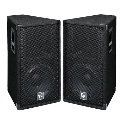
  9. Electro-Voice DeltaMax DMS-1152/64 Series User manual

Electro-Voice DeltaMax DMS-1152/64 Series User manual

DMS-1152/64
Series
DeltaMaxTM Two-Way,
Full-Range, Electronically
Controlled Sound-
Reinforcement System
• Substantially improved vocal
range performance
• New EVX-155 woofer with
almost 3-dB additional LF
output, more power handling/
lower distortion
• New DH2T compression driver
• New HF horn (60° x 40°) fully
rotatable for vertical or horizon-
tal suspension
Description
The Electro-Voice DMS-1152/64 full-range
loudspeaker system is part of the
DeltaMaxTM series and is intended for high-
level sound reinforcement in fixed-instal-
lation and touring sound applications. The
DMS-1152/64 is a two-way biamped loud-
speaker system designed to be used with
the dedicated DMC-1152X analog elec-
tronic controller. The DMS-1152/64 may
also be used with appropriate factory pre-
sets with the Electro-Voice Dx34 digital
crossover. In addition to providing con-
ventional frequency division, time delay
and equalization, DMC-1152X offers
unique speaker protection circuitry to pro-
vide excellent reliability. This loudspeaker
system and the associated electronic con-
trollers were designed as an integral pack-
age to achieve maximum acoustic output
with optimal sonic quality. The DMS-1152/
64 is available in the following models:
DMS-1152/64P which is a non-flying black-
painted version; DMS-1152/64PF which is
equipped with rigging track flying hard-
ware and is also painted black.
The DMS-1152/64 employs the 15-inch
EVX-155 woofer for low-frequency repro-
duction. This new design offers optimal
sensitivity and maximum linear excursion.
The combination provides extremely high
low-frequency output capability and power
handling.
For high frequencies, the DMS-1152/64
uses the DH2T compression driver. This
new design features one-piece titanium
dome and suspension with integral stiff-
ening ribs to provide extremely high out-
put and substantially reduced distortion
through the critical vocal frequencies.
The DH2T compression driver is coupled
to the HP64M flat-front constant-directiv-
ity horn. This 60° x 40° design is optimized
for performance from 800 Hz to 20 kHz (the
crossover in the DMS-1152/64 is 1,480 Hz).
This horn has a square front, allowing full
rotatability. This feature allows cabinets
to be hung either horizontally or vertically
and still maintain 60° x 40° pattern for de-
sired coverage.
The DMS-1152/64 is constructed of 18-mm,
13-ply birch plywood and is available in a
wear-resistant black, textured paint finish
(DMS-1152/64P). The system is trapezoi-
dal in shape, forming a 30° wedge, and in-
cludes a protective steel-grille sandwich.
This grille sandwich consists of two layers
of vinyl-clad perforated metal with a water-
resistant charcoal-gray foam interlining.
The optional flying version includes two
sections of full tracks on the top and bot-
tom to facilitate hanging of multi-cabinet
arrays or permanent installations (DMS-
1152/64PF).
In addition, the DMS-1152/64 version se-
ries all have a built-in stand adapter for
mounting the loudspeaker on 1.375-inch-
diameter pole stand (such as the Electro-
Voice 100BK).
Applications
The DMS-1152/64 loudspeaker system is
ideal for any professional touring or instal-
lation application requiring accurate, high-
level sound reinforcement. Because of the
unique performance capabilities featured
in this system, the DeltaMaxTM DMS-1152/
64 offers on extremely wide-range music
reproduction as well as accurate vocal cov-
erage and maximized intelligibility.
The DMS-1152/64 and associated control-
ler combinations are recommended for ap-
plications requiring full bandwidth down
to 50 Hz. Where very high levels of deep
bass are required, maximum performance
may be achieved with the addition of the
DMS-2181 (double 18-inch subwoofer) or
DMS-1181 (single 18-inch subwoofer).
Both of these subwoofer systems feature
the EVX-180A 18-inch subwoofer and are
designed to be used with associated con-
trollers (see data sheets on DMS-2181 or
DMS-1181).
DeltaMaxTM DMS-1152/64 Loudspeaker System
DeltaMax
TM
DMS-1152/64LoudspeakerSystem
2
Power-Handling Test
Electro-Voice components and systems are
manufactured to exacting standards to en-
sure reliability in continuous use in ardu-
ous real-life conditions. Besides utilizing
industry-standard power tests, extreme in-
house power tests which push the perfor-
mance bounadries of the loudspeakers are
also performed for an extra measure of reli-
ability. The DMS-1152/64 systems are rated
per ANSI/EIA RS-426-A Loudspeaker
Power Rating, Full Range Test, which uses
a shaped-random-noise signal to simulate
typical music to test the mechanical and
thermal capabilities of the loudspeakers.
The Dx34 digital electronic unit was used
to provide the necessary crossover filters
and equalization during power testing.
Specifically, the DMS-1152/64 passes the
ANSI/EIA RS-426-A power test with the
follwing test parameters:
Low-Frequency Section:
PE(MAX): 600 watts
Test Voltages: 58.7 volts rms
117.4 volts peak
RSR(1.15RE): 5.75 ohms
High-Frequency Section:
PE(MAX): 60 watts
Test Voltages: 17.6 volts rms
35.2 volts peak
RSR(1.15RE): 5.18 ohms
Crossover, Equalization and Time-Delay
Controller
The DMS-1152/64 speaker system and vari-
ants are designed as an integrated pack-
age that utilizes any of the following con-
trollers:DMC-1152X,orElectro-VoiceDx34
digital crossover system. Optimal perfor-
mance of the DMS-1152/64 speaker sys-
tem can only be assured when using the
above referenced controllers.
All controllers used with the DMS-1152/
64 feature a 1,480-Hz crossover frequency
utilizing 24-dB-per-octave Linkwitz-Riley
filters. All contain fixed time delay and
equalization for optimum performance of
the DMS-1152/64. Protection circuitry in
the DMC-1152X controller also ensures
maximum reliability and functionality.
Electrical Connection and System
Wiring
Electrical connections to the DMS-1152/
64 are made on the back of the enclosure
via a 4-pin conncector. There are two con-
nectors on the input panel to allow paral-
leling of other DMS-1152/64 systems. The
Neutrik Speakon®NL4MPR is used for
both connections. The pin assignments
are as follows:
Pin 1+: LF(+)
Pin 1-: LF(–)
Pin 2+: HF(+)
Pin 2-: HF(–)
The wiring diagram of the loudspeaker sys-
tem is shown in Figure 7. The electrical
impedance is shown in Figure 6.
Amplifier Requirements
Power amplfiers with the following ratings
are recommended for use with the DMS-
1152/64 speaker systems:
LF: 600-1,200 watts continuous into 8 ohms
HF: 125-250 watts continuous into 8 ohms
DMS-1152/64 speakers may be paralleled
only with other DMS-1152/64 speakers if
the amplifier is capable of delivering full
power at the lower impedances. The use
of amplifiers with lower power ratings is
acceptable; however, the full-power capa-
bilities of the DMS speakers will not be
realized. The use of amplifiers with signifi-
cantly higher power ratings will generate
maximum dynamic range and fidelity, but
care must be utilized for longer duration
signals as mechanical and thermal damage
are possible in the system. Under certain
circumstances, higher rated amplifiers are
acceptable. It is acceptable to drive the
DMS-1152/64 speakers with a stereo power
amp utilizing one channel to drive the low
frequencies and the other channel to drive
the high frequencies. See owner's manu-
als on various controllers for appropriate
settings.
Flying the DMS Systems
A manual entitled the DMS Flying Manual
is available from Electro-Voice, and is in-
cluded with each flying DMS loudspeaker
system. A brief introductory overview is
included here. The DMS Flying Manual
should be consulted for complete struc-
tural specifications and detailed informa-
tion on safely suspending and using the
DMS systems.
The DMS-1152/64PF is the version of the
DMS-1152/64 loudspeaker system that in-
cludes flying hardware. The DMS sys-
tems incorporate a unique, two-point fly-
ing system that permits a wide range of
vertical angle adjustment, and offers maxi-
mum flexibility in array design for both tour-
ing sound and permanent installations.
The quick release, aircraft-rated, heavy-
duty L-track-type hardware design allows
arrays of loudspeakers to be assembled
(and disassembled) very quickly, and of-
fers such flexibility in the vertical angling
of cabinets that pull-up points are usually
unnecessary. Furthermore, all of the fly-
ing DMS loudspeaker models include the
same rigging hardware, allowing different
models to be mixed as necessary through-
out an array.
The working-load limit (for an 8:1 safety
factor) for each rigging point on the DMS
loudspeaker enclosure is 227 kg (500 lb)
for a 0° pull angle and 170 kg (375 lb) for a
90° pull angle when used with the New
Haven NH32101-2S double-stud fitting,
and 113 kg (250 lb) when used with the
New Haven NH8192-2 or Ancra 42546-10
single-stud fittings with locking pins. The
working-load limit (for an 8:1 safety fac-
tor) for the overall enclosure is 340 kg (750
lb). (Consult the DMS Flying Manual for
specific structural ratings and limitations.)
The enclosures may be oriented with the
rigging track on the sides of the enclosure,
or on the top and bottom, and may be
daisy-chained together as long as the
safety factor is 8:1 or greater, and local
regulations are met. For fire safety and ad-
ditional structural strength in both flying
orientations, top-to-bottom and side-to-
side metal straps link the rigging track in-
side the enclosure. Electro-Voice offers a
line of flying-hardware accessories for use
with the DMS loudspeaker systems. All
associated rigging is the responsibility of
others.
CAUTION: The DMS loudspeaker sys-
temshould besuspended overheadonlyin
accordance with the procedures and limi-
tations specified in the DMS Flying
Manual and manual updates notices.
Field Replacement
DeltaMax
TM
DMS-1152/64 Loudspeaker System
DeltaMax
TM
DMS-1152/64LoudspeakerSystem
3
The DMS-1152/64 was designed for expe-
dient field service. Removing the woofer
bolts allows the woofer to be easily re-
moved. Removing the horn-mounting
screws allows access to the compression
driver, both through the horn and woofer
baffle cutouts. A woofer failure will re-
quire replacement of the entire driver. In
the case of a compression driver failure, a
diaphragm assembly replacement kit with
instructions is available. If desired, the
complete driver may be returned for ser-
vice.
The following replacement parts are avail-
able from Mark IV Audio Service in Bucha-
nan, Michigan:
LF:Complete woofer:EVPart No. 815-2738
HF: Diaphragm kit; EV Part No. 81161-XX
Architects' and Engineers'
Specifications
The loudspeaker system shall be a two-
way biamped system with performance
controlled by a variety of dedicated elec-
tronic control units. The loudspeaker sys-
tem shall have a 15-inch, low-frequency, di-
rect-radiating driver with an 8-ohm, 4-inch
voice coil constructed of aluminum wire, and
shall be capable of a 600-watt shaped
pink-noise signal with a 6-dB crest fac-
tor for 8 hours (as per ANSI/EIA RS-
426-A 1980 standard). The loudspeaker
system shall have a 25.4 mm (1.0-inch) exit
compression driver mounted on a high-fre-
quency horn. The compression driver shall
have 50.8-mm (2.0-inch) diameter, .001-inch
thick titanium dome and an 8-ohm nomi-
nal, 50.8-mm (2.0-inch) diameter voice coil
constructed of aluminum wire, and which
shall be capable of handling a 60-watt, 1,480
to 20,000 Hz pink-noise signal with a 6-dB
crest factor for 8 hours (as per EIA RS-
426-A 1980 standard). The high-frequency
horn shall be of the constant-directivity
type and fully rotatable and shall produce
a nominal horizontal beamwidth (6-dB-
down angle) of 60° from 2,000 to 20,000 Hz,
and a nominal vertical beamwidth of 40°
from 1,600 to 20,000 Hz. The loudspeaker
system enclosure shall be constructed of
18-mm thick 13-ply birch plywood, trap-
ezoidal in shape, forming a 30° wedge, and
shall have a vinyl-clad steel-grille system.
The DMS-1152/64 system shall be used
with recommended control systems and
shall have a two-way crossover circuit with
fourth-order Linkwitz-Riley filters, equal-
ization, time delay and protection circuitry.
When used with the electronic control unit,
the loudspeaker system shall have a flat
on-axis frequency response from 50 to
16,000 Hz. The loudspeaker enclosure di-
mensions shall be 759 mm (29.88 inches)
high, 450 mm (17.73 inches) wide and
413 mm (16.26 inches) deep and shall
weigh 35.4 kg (78 lb). The system shall
incorporate a two-point rigging system
that will accept New Haven NH32101-2
double-stud ring fittings and the New Ha-
ven NH8192-2.5 and Ancva 4254C-10
single-stud fittings.
The loudspeaker shall be Electro-Voice
DMS-1152/64 (and its variants).
Limited Warranty
Electro-Voice products are guaranteed
against malfunction due to defects in ma-
terials or workmanship for a specified pe-
riod, as noted in the individual product-
line statement(s) below, or in the individual
product data sheet or owner’s manual, be-
ginning with the date of original purchase.
If such malfunction occurs during the
specified period, the product will be re-
paired or replaced (at our option) without
charge. The product will be returned to the
customer prepaid. Exclusions and Limita-
tions: The Limited Warranty does not ap-
ply to: (a) exterior finish or appearance; (b)
certain specific items described in the indi-
vidual product-line statement(s) below, or
in the individual product data sheet or
owner’s manual; (c) malfunction resulting
from use or operation of the product other
than as specified in the product data sheet
or owner’s manual; (d) malfunction result-
ing from misuse or abuse of the product;
or (e) malfunction occurring at any time
after repairs have been made to the prod-
uct by anyone other than EVI Audio Ser-
vice or any of its authorized service repre-
sentatives. Obtaining Warranty Service:
To obtain warranty service, a customer
must deliver the product, prepaid, to
EVI Audio Service or any of its authorized
service representatives together with proof
of purchase of the product in the form of a
bill of sale or receipted invoice. A list of
authorized service representatives is avail-
able from EVI Audio Service at 600 Cecil
Street, Buchanan, MI 49107 (800/234-6831
orFAX616/695-4743). IncidentalandCon-
sequential Damages Excluded: Product re-
pair or replacement and return to the cus-
tomer are the only remedies provided to
the customer. Electro-Voice shall not be li-
able for any incidental or consequential
damages including, without limitation, in-
jury to persons or property or loss of use.
Some states do not allow the exclusion or
limitation of incidental or consequential
damages so the above limitation or exclu-
sion may not apply to you. Other Rights:
This warranty gives you specific legal
rights, and you may also have other rights
which vary from state to state.
Electro-Voice Speakers and Speaker Sys-
tems are guaranteed against malfunction
due to defects in materials or workman-
ship for a period of five (5) years from the
date of original purchase. The Limited
Warranty does not apply to burned voice
coils or malfunctions such as cone and/or
coil damage resulting from improperly de-
signed enclosures. Electro-Voice active
electronics associated with the speaker
systems are guaranteed for three (3) years
from the date of original purchase. Addi-
tional details are included in the Uniform
Limited Warranty statement.
Electro-Voice Accessories are guaranteed
against malfunction due to defects in ma-
terials or workmanship for a period of one
(1) year from the date of original purchase.
Additional details are included in the Uni-
form Limited Warranty statement.
Electro-Voice Flying Hardware (including
enclosure-mounted hardware and rigging
accessories) is guaranteed against mal-
function due to defects in materials or
workmanship for a period of one (1) year
from the date of original purchase. Addi-
tional details are included in the Uniform
Limited Warranty statement.
For warranty repair or service informa-
tion, contact the service repair department
at: 616/695-6831 or 800/685-2606.
For technical assistance, contact Technical
Supportat800/234-6831or616/695-6831,M-
F, 8:00 a.m. to 5:00 p.m. Eastern Standard
Time.
Specifications subject to change without
notice.
DeltaMaxTM DMS-1152/64 Loudspeaker System
DeltaMax
TM
DMS-1152/64LoudspeakerSystem
4
Horizontal
Vertical
Figure 1— Polar Response
The directional response of the system was measured in an anechoic environment at a distance of 6.1m (22 feet) using 1/3-octave-filtered
pink noise with a full spherical measurement system. The Dx34 digital electronic unit was used to provide the necessary crossover filters,
equalization and time delay. The polar response of the loudspeaker system at selected 1/3-octave frequencies is shown. The selected
frequencies are representative of the polar response of the system.
5 dB per division
800 Hz250 Hz 500 Hz
1,000 Hz 1,250 Hz 1,600 Hz
2,000Hz 2,500Hz 3,150Hz
DeltaMax
TM
DMS-1152/64 Loudspeaker System
DeltaMax
TM
DMS-1152/64LoudspeakerSystem
5
Horizontal
Vertical
Figure 2—Frequency Response
The frequency response of the system was
measured on axis in the farfield in an
anechoic environment using a swept sine-
wave signal. The Dx34 digital electronic
unit was used to provide the necessary
crossover filters, equalization and time de-
lay. One watt of power (2.83 volts rms at
250 Hz) was applied to the midband of the
low-frequency section. The sound-pres-
sure level was normalized for an equiva-
lent one meter distance.
5 dB per division
8,000Hz 10,000 Hz 16,000Hz
4,000Hz 5,000Hz 6,300Hz
DeltaMaxTM DMS-1152/64 Loudspeaker System
DeltaMax
TM
DMS-1152/64LoudspeakerSystem
6
Figure 4—Directivity
The directivity index, Di, and directivity fac-
tor, R θ(Q), of the system were measured
with a full spherical measurement system
as described for the "Polar Response."
Figure 5—Distortion
Distortion for the system was measured
on axis in the farfield in an anechoic envi-
ronment with an input signal that would
result in a sound-pressure level of 115 dB
at one meter. The Dx34 digital electronic
unit was used to provide the necessary
crossover filters, equalization and time de-
lay. A frequency spectrum typical of close-
mic’d rock music was employed. The
sound-pressure level was normalized for
an equivalent one-meter distance. Plots of
second and third harmonic distortion are
shown referenced to the fundamental.
Figure 3—Beamwidth
The beamwidth of the system, (i.e., the in-
cluded horizontal and vertical coverage
angles at the 6-dB down point) was mea-
sured with a full spherical measurement
system as described in "Polar Response."
DeltaMax
TM
DMS-1152/64 Loudspeaker System
DeltaMax
TM
DMS-1152/64LoudspeakerSystem
7
HF
LF
Figure6—Impedance
The impedance of each frequency band of
the system was measured in an anechoic
environment.
Figure 7—Wiring Diagram
The wiring diagram of each frequency band
of the system is shown.
Figure 8—Dimensions
DeltaMaxTM DMS-1152/64 Loudspeaker System
DeltaMax
TM
DMS-1152/64LoudspeakerSystem
8
Specifications
Frequency Response (measured in far
field, calculated to one meter on axis,
sweptsi newave, onewatt intoLF
section 2.83 V at 250 Hz, anechoic
environment; see Figure 2):
50-16,000Hz
Crossover Frequency:
1,480Hz
Efficiency, LF/HF:
4.2/25 %
MaximumLong-Term-AveragePower-
HandlingCapacity (perANSI/EIARS-
426-A 1980), LF/HF:
600/60 watts
MaximumLong-Term-Average Midband
AcousticOutput, LF/HF:
25/15 acoustic watts
Sensitivity (SPL at one meter, indicated
inputpower,anechoicenvironment,
averagelevel), LF/HF,
1/1 watt:
98.0/113.0dB
300/60 watts:
125.5/131.0dB
Beamwidth(angle includedby 6-dB-
down points on polar responses, indi-
catedone-third-octave bandsofpink
noise; see Figures 1 and 3),
Horizontal, 1,200-16,000 Hz:
60° (+40°, –5°)
Vertical, 1,200-16,000 Hz:
40°(+28°, –15°)
Directivity Factor, Rθθ
θθ
θ(Q), 1,200-16,000
Hz Average (see Figure 4):
19.7(+7.2, –6.8)
Directivity Index, Di, 1,200-16,000 Hz
Average (see Figure 4):
13.0 dB (+1.4 dB, –1.8 dB)
Distortion (115 dB SPL at one meter,
shaped spectrum; see Figure 5),
SecondHarmonic,
100 Hz:
1.6 %
500 Hz:
0.9 %
2,000 Hz:
1.3 %
5,000 Hz:
1.0 %
ThirdHarmonic,
100 Hz:
0.3 %
500 Hz:
1.0 %
2,000 Hz:
<0.1 %
5,000 Hz:
<0.1 %
Transducer Complement,
HF:
DH2T driver, HP 64M 60° x 40° horn
LF:
EVX-15515-in. woofer
Impedance (see Figure 6),
Nominal,LF/HF:
8/8 ohms
Minimum,LF/HF:
7.4/6.9 ohms
InputConnections:
Two Neutrik NL4MPR Speakon®
connectors paralleled
RecommendedAmplifier Power,
HF:
125-250 watts
LF:
600-1,200 watts
Enclosure Construction,
Enclosure Shell:
18 mm, 13-ply birch plywood
Finish:
Black textured paint
Grille:
Vinyl-coated steel with foam
Rigging (DMS-1152/64PF only):
Two-point heavy-duty L-track system,
accepts New Haven NH32102-2
double-stud fittings, or New Haven
NH8192-2S or Ancra 42546-10 single-
stud fittings with safety pins
Dimensions,
Height:
759mm (29.88 in.)
Width(front):
450mm (17.73 in.)
Width(back):
248mm (9.75 in.)
Depth:
413mm (16.28 in.)
Angle:
30° wedge
Net Weight:
35.4 kg (78 lb)
Shipping Weight:
37.6 kg (83 lb)
600 Cecil Street, Buchanan, MI 49107
800/234-6831,616/695-6831,Fax 616/695-1304
SPEAKERS—MT and DeltaMaxTM Part Number 533480—9806

Other Electro-Voice Speakers System manuals

Electro-Voice Xlvc Series XLD-281 User manual

Electro-Voice

Electro-Voice Xlvc Series XLD-281 User manual

Electro-Voice FRX+640 User manual

Electro-Voice

Electro-Voice FRX+640 User manual

Electro-Voice EVR-160 User manual

Electro-Voice

Electro-Voice EVR-160 User manual

Electro-Voice Phoenix PX2122 User manual

Electro-Voice

Electro-Voice Phoenix PX2122 User manual

Electro-Voice TL440 User manual

Electro-Voice

Electro-Voice TL440 User manual

Electro-Voice MTL-4B User manual

Electro-Voice

Electro-Voice MTL-4B User manual

Electro-Voice EVH-1152S/43 User manual

Electro-Voice

Electro-Voice EVH-1152S/43 User manual

Electro-Voice EVA-2082S/906EVA-2082S/920EVA-2082S/126 User manual

Electro-Voice

Electro-Voice EVA-2082S/906EVA-2082S/920EVA-2082S/126 User manual

Electro-Voice MTH-1 User manual

Electro-Voice

Electro-Voice MTH-1 User manual

Electro-Voice SL8.2 User manual

Electro-Voice

Electro-Voice SL8.2 User manual

Electro-Voice DeltaMax DMS-1122/85 Series User manual

Electro-Voice

Electro-Voice DeltaMax DMS-1122/85 Series User manual

Electro-Voice X-Array Install Xi-1122-85 User manual

Electro-Voice

Electro-Voice X-Array Install Xi-1122-85 User manual

Electro-Voice EVS-14B User manual

Electro-Voice

Electro-Voice EVS-14B User manual

Electro-Voice Speaker System User manual

Electro-Voice

Electro-Voice Speaker System User manual

Electro-Voice Xi-1152/94 User manual

Electro-Voice

Electro-Voice Xi-1152/94 User manual

Electro-Voice EVH-1152D/99 User manual

Electro-Voice

Electro-Voice EVH-1152D/99 User manual

Electro-Voice TL15-1ES User manual

Electro-Voice

Electro-Voice TL15-1ES User manual

Electro-Voice TL15-2 User manual

Electro-Voice

Electro-Voice TL15-2 User manual

Electro-Voice SH-1502 User manual

Electro-Voice

Electro-Voice SH-1502 User manual

Electro-Voice SENTRY IV Dimension Guide

Electro-Voice

Electro-Voice SENTRY IV Dimension Guide

Electro-Voice FR12-2 User manual

Electro-Voice

Electro-Voice FR12-2 User manual

Electro-Voice XI 1191 User guide

Electro-Voice

Electro-Voice XI 1191 User guide

Electro-Voice Royal 400 User manual

Electro-Voice

Electro-Voice Royal 400 User manual

Electro-Voice Xi-A Series User manual

Electro-Voice

Electro-Voice Xi-A Series User manual

Popular Speakers System manuals by other brands

RCA rts736w user manual

RCA

RCA rts736w user manual

Sven MS-306 Operation manual

Sven

Sven MS-306 Operation manual

JVC MX-GB5C instructions

JVC

JVC MX-GB5C instructions

Behringer Eurolive B212 user manual

Behringer

Behringer Eurolive B212 user manual

Bose SMART SOUNDBAR 700 manual

Bose

Bose SMART SOUNDBAR 700 manual

EAW Cinema CR71 Technical specifications

EAW

EAW Cinema CR71 Technical specifications

Yamaha NS-7390 owner's manual

Yamaha

Yamaha NS-7390 owner's manual

Energy RC-6C owner's manual

Energy

Energy RC-6C owner's manual

Yamaha NS-10MMF owner's manual

Yamaha

Yamaha NS-10MMF owner's manual

Sony WALKMAN SRS-NWGT10 operating instructions

Sony

Sony WALKMAN SRS-NWGT10 operating instructions

Technics SB-C700 owner's manual

Technics

Technics SB-C700 owner's manual

Acoustic Research ARS500 Hi-Res Series owner's manual

Acoustic Research

Acoustic Research ARS500 Hi-Res Series owner's manual

Tannoy VQ Series quick start guide

Tannoy

Tannoy VQ Series quick start guide

EAW Virtural Array KF850ZR Specifications

EAW

EAW Virtural Array KF850ZR Specifications

LEXIBOOK BT1000 series manual

LEXIBOOK

LEXIBOOK BT1000 series manual

JBL CM52 Technical manual

JBL

JBL CM52 Technical manual

Yamaha MCX-SP10 - Left / Right CH Speakers owner's manual

Yamaha

Yamaha MCX-SP10 - Left / Right CH Speakers owner's manual

Powerwerks PW50 owner's manual

Powerwerks

Powerwerks PW50 owner's manual

manuals.online logo
manuals.online logoBrands
  • About & Mission
  • Contact us
  • Privacy Policy
  • Terms and Conditions

Copyright 2025 Manuals.Online. All Rights Reserved.