manuals.online logo
Brands
  1. Home
  2. •
  3. Brands
  4. •
  5. Electro-Voice
  6. •
  7. Speakers
  8. •
  9. Electro-Voice PIM-151 Owner's manual

Electro-Voice PIM-151 Owner's manual

/
./
ElectroVoice®
..........
.
SPECIFICATIONS
Versions Available:
See PIM-151 ordering matrix (Figure
1)
Typical Axial Frequency Response,
(swept sine-wave Input, anechoic
environment, 4
volts
at 1 kHz
at 10 feet; see Figure 2):
45-1,800
Hz
Low-Frequency 3-d8-Down Point,
Normal:
45
Hz
Step-Down (with equalization):
32
Hz
Usable Low-Frequency
limit
(10-d8-down point):
Normal:
30
Hz
Step-Down (with equalization):
26
Hz
Recommended Crossover Frequency:
80-200 Hz
Crossover Slopes,
Recommended:
24
dB per octave
Minimum:
12
dB per octave
Long-Term Average Power-Handling
Capacity (per
EIA
RS-426-A
1980;
see
Power-Handling Test section):
600
watts
Sensitivity (far-field SPL referred
to
1 meter, 1-waH input, anechoic environ-
ment, band-limited
pink
noise),
100-800 Hz:
96
dB
SPL at Full Power (far-field SPL at 1 watt!
1 meter referred
to
full
power, anechoic
environment, band-limited
pink
noise
100-800 Hz), Long-Term Average/Peak,
124 dB/130 dB
Impedance,
Nominal:
8 ohms
Minimum:
6.9 ohms
Half-Space Reference Efficiency:
4.32%
PIM-151
(standard
configuration)
15-lnch,
Vented
Low-Frequency
System
for
Pennanent
Installation
•
Part
of
PI
Matrix
SeriesnL...compact
trapezoidal
systems
•
Components
and
physical
characteristics
optional,
to
meet
many
acoustic,
architectural
and
mechanical
requirements
•
Extends
response
to
45
Hz
(32
Hz
in
step-down
mode)
•
Integral
suspension
system
for
safe
and
easy
installation
Directivity Index 01
,
(1010g,oR.,),
50-125 Hz:
8eamwidth (angle Included by S-d8-down
points on polar responses, Indicated one-
third-octave bands of
pink
noise; see
Figure 3):
0.0 dB
400-800 Hz:
6.6dB
Distortion Response 1% Rated Input
Power at 100
Hz
(on axis at 1 meter from
system),
50
to
125 Hz Horizontal:
360·
400
to
800
Hz
Vertical:
129·,
±10·
Second Harmonic:
50
Hz: 4.0%
Directivity Factor
Re
(Q), Median over
Indicated Range (see Figure 4):
50-125 Hz:
80
Hz: 2.8%
200 Hz: <1.0%
Third Harmonic,
50
Hz:
<1
.0%
80
Hz:
<1
.0%
200 Hz: <1.0%
1.0
400-800 Hz:
4.5
FIGURE 1 - PIM-151 Ordering Matrix
NOTE: Examole is the standardsYstem confiauration
Options
(or
IPIMI
151Iolxlxl-lcl-loIAIAlx
XX
Misc2:
PIM-151 X = none
-.
f 1
I
151
= IS-inch LF system r I
Mise
1:
1X =none
Wooters: A = handles
A =DL15X
B = DL15X-16 Crossover:
C = NlA
D = EVX-150A
l......-
X = none
L.....-
HF Drivers:
X = none
L...--
Rigging:
X = none A =Ancra
Enclosure Finish/Materials: Grille: B = metal w/foam I
A = unfinished, 7-ply birch
B = unfinished, 14-ply birch
A=metal
C = textured blk paint, 7-ply birch
'51DXX-C-DAAXXX. D = textured blk paint, 14-ply birch Input Panel:
15·inch
LF
with EVX-I50A, Horns: E = Woiverineil> ureth., 7-ply birch
A=NlA
7-p1y
birch enclosure,
X=
none F = Wolverineil> ureth., 14-ply birch
B=NlA
painted black, barrier strip. G = white primer, 7-ply birch C = Speakonil>, passive
metal grille, flying
hardware for Ancra H = white primer, 14-ply birch D = barrier strip, passive
42546-10's and
no
misc.
Items.
PIM-151 SPECIFICATION GRAPHICS
FIGURE 2 -
PIM-151
Typical Axial Frequency Response (sweptsine-wave
Input, anechoic environment, 4 volts at
10
feet normalized for
1 watt at 1meter)
100
.,90
..,
.E
oJ
l};80
70
.
~
-M
..
lI'
1\
II
I'
.. ..
,
..
--,- -
FREQUENCY IN HERTZ
FIGURE 3 -
PIM-151
Beamwldth VB. Frequency (one-third-octave bands
of
pink
noise)
-360
i:
'"
...
...
ffi
1:
o
..
~
~
:
~
20
C
w
.,
~
A=HORIZONTAL·
0= VERTICAL·
~~
FREOUENCY
IN
HERTZ
FIGURE 4 -
PIM-151
Directivity Factor and Directivity Index vs. Frequency
(one-third-octave bands
of
pink
noise)
.,
3
...
o
1.'1
o 2
~
~
0
0
> 10
t
w
II:
f-
is
o.
_
I
1.1
~
5;2
8~=
5-)-0
Sll~~~".;;
;U
3539S
.......
::'00,,.;")' I
ffiR"I
II
III
IT
I
,.
-
FREQUENCY IN
HERTZ
10000
rz!
1
1
1
II:
oo~
~
~
t
w
II:
is
FIGURE 5-
PIM-151
Harmonic Distortion, 10% Rated Input Power
at 100 Hz (on axis at 1 meter from system)
III
"0
"
100
90
8
0
0
:J60
w
~
50
4
o
I.
I
30 I
I-
0
1/\
~
1\
II
II
It'
1.\11
r\
1'1
Ill\-~
I
.,
t
'I
IU
I
~
I
2nd HARMONIC
--
~
3rd HARMONIC - -
I
~
I
FREOUENCY IN HERTZ
• Long enclosure axis vertical.
FIGURE 6 - PIM-151 Dimensions
911
mm
(35.9 In.)
o
430mm
(lUln.)
575mm
(22.7 In.)
o
FIGURE 7 -
PIM-151
Polar Responses, Selected
to
Typify
Performance
(one-third-octave bands
of
pink
noise)
5
dB
PER
DIVISION HORIZONTAL(LONG ENCLOSURE AXIS VERTICAL)
---
VERTICAL
----
Distortion
Response
10%
Rated
Input
Power
at
100 Hz
(on
axis
at
1
meter
from
system;
see
Figure
5),
Second
Harmonic,
50 Hz: 9.0%
80 Hz: 5.0%
200 Hz: <1.0%
Third
Harmonic,
50 Hz: 3.5%
80 Hz: 1.3%
200 Hz: <1.0%
Transducer
Complement,
Low
Frequency:
EVX150A 381-mm (15-in.) woofer
in
a vented enclosure
Box
Tuning
Frequency,
Normal:
38Hz
Step-Down:
27 Hz
Polarity:
A positive voltage applied to the positively
marked input terminal produces a positive
acoustic pressure at the front of the
system
Input
Connections:
#10 screw terminals on barrier strip; each
driver can be individually accessed
Enclosure
Materials
and
Color:
Textured black painted 7-ply void-free
birch
Grille:
Black powder coated, vibration-resistant
steel, removable
Suspension:
Integral three-point flying system (accepts
Ancra 42546-10 single-stud tie-down cargo
fitting; four fittings supplied with system;
see Suspending PIM-151 Enclosures
section)
Dimensions
(see
Figure
6),
Height:
911
mm (35.9 in.)
Width
at
Front:
575 mm (22.7 in.)
Width
at
Rear:
359 mm (14.1 in.)
Depth:
438 mm (17.2 in.)
Side-Wail
Draft
Angle:
15°
Net
Weight:
34.0
kg
(75 Ib)
Shipping
Weight:
40.0 kg (85 Ib)
DESCRIPTION
AND
APPLICATIONS
The Electro-Voice PIM-151 is a compact, trap-
ezoidallow-frequency speakersystem for per-
manentinstallation. A 15-inchwooferismounted
in an optimally vented enclosure. The PIM-151
is part of the
PI
Matrix Series
Tt
",
a highlyflexible
group of full-range and low-frequency systems
for applications where compact systems are
appropriate. Many performing arts centers,
clubs, auditoriums, sportsfacilities and houses
of worship are candidates for the
PI
Matrix
Series
Tl
•
4•
The flexibility of the
PI
Matrix Series™ allows
the designerto customize a system to both suit
the acoustic environment and meet a wide
varietyofarchitectural and mechanical require-
ments.
PIM-151 options include low-frequency driv-
ers, enclosure materials and finish, grilles,
suspension hardware and input-panel con-
nections, giving the sound contractor or con-
suitant literally thousands
of
combinations to
satisfy the overall system design criteria.
The PIM-151 standard configuration employs
the EVX-150A 381-mm (15-inch) long-throw,
extended-reliabilitywoofer. Operatingbetween
45 and 1,800 Hz
in
a compact enclosure, the
EVX-150Acan handle very high levels ofinput
power, producing high acoustic output with
relatively low distortion.
The PIM-151 is equipped with a number of
additional features to make operation and in-
stallation easy and secure. A proprietarystruc-
tural extrusion is incorporated into the enclo-
sure, providing safe and flexible suspension
(seeSuspending PIM-151 Enclosuressection).
Up to two enclosures of the same footprint can
be suspended without additional support (as
long asthe lowersystem is notheavierthan the
uppersystem), soarrayscan becreatedquickly
and easily. The grille is composed ofvibration-
resistant steel for excellent driver protection,
and an optional foam cover can be added for
betterprotection when used outdoors. Besides
the standard black-painted finish, the enclo-
sure can also be ordered primed in white for
painting with ordinary paints, unfinished for
staining orwith ourspecialWolverine<!>weather-
resistant finish for outdoor applications. The
PIM-151 drivercan be serviced from the front of
the enclosure.
A
complete
listing
of
all
system
options
Is
shown
In
Figure
1.
SUSPENDING PIM-151 ENCLOSURES
Suspending
any
object is potentially danger-
ous
and
shouldbe attempted only
by
individu-
als who have a thorough knowledge
of
the
techniques
and
regulations
of
hanging over-
head. Electro-Voice stronglyrecommends that
the PIM-151 besuspended taking into account
all current national, federal, state
and
local
regulations. It is the responsibility
of
the in-
staller
to
ensure that the PIM-151 is safely
installed in accordance with all such regula-
tions.
If
the PIM-151 is suspended, Electro-
Voice stronglyrecommends thatthe systembe
inspected
at
least once a year.
If
any
sign
of
weakness
or
damage is detected, remedial
action should be taken immediately.
The
PI
Matrix Series™ enclosures are sus-
pended using the following approach, which
has been approved by an independent struc-
tural engineer. Every enclosure incorporates
six independent suspension points, three on
the top and three on the bottom. A minimum of
three points must be used at all times to sus-
pend the enclosure. The suspension points,
which "tie" the top and sides of the enclosure
together, are made of structural aluminum.
Each suspension point mates to an Ancra
42546-10 locking fitting (four are supplied with
each enclosure ordered with this option, EV
#20562), andeachpointhasabreakstrength of
907 kg (2,000 Ib) in anydirection.' A maximum
of two enclosures can be "daisy chained" to-
gether, allowing the construction of vertical
arrays. This also applies to other PIM models
with the same footprint, as long as the lower
system is no heavierthan the upper system. If
the lower system is heavier,
or
if longer arrays
are required, provision must be made to inde-
pendentlysuspend each enclosure. The Ancra
42546-10 fitting incorporates a safety pin to
prevent accidental release, and it should be
engaged at all times.
CONNECTIONS
Depending on the option ordered, barrier strip
or Neutrik
Speakon<!>
connectors are used for
input connections. Both barrier strips are wired
in
parallel and connected to the single woofer.
In
the
Speakon<!>
connector options, pins 1
+/1-
and 2+/2- are
in
parallel and connected to the
woofer. The driveris connected so that a posi-
tive voltage applied to the positively marked
terminal will produce a positive acoustic pres-
sure at the front of the system.
FREQUENCY RESPONSE
PIM-151 axial frequency response was mea-
sured in Electro-Voice's large anechoic cham-
ber
at a distance of 3.0 meters (10 feet) with
swept sine-wave input. Figure 2 shows the
typical system response, with a 4-volt drive,
normalized for a 1-watt input and a 1-meter
distance.
DIRECTIVITY
The directional characteristics of the PIM-151
were
measured
in
Electro-Voice's
large
anechoic chamber, with a test signal of one-
third-octave filtered pink noise at the frequen-
cies indicated. A full spherical measurement
system, which is fully compatible with Mark IV
Audio's AcoustaCADDTM computer-aided
de-
sign program, was used. All directional infor-
mation was measured at
6.1
meters (20 feet).
Figure 7 illustrates the nominal horizontal and
vertical polar responses, with the long system
axis vertical.
Figure 3 illustrates the horizontal and vertical
beamwidths. Beamwidth is the angle at which
the horizontal and vertical polar responses
have decreased in level by 6 dB when com-
pared to the on-axis frequency response.
Figure 4 represents the total directivity of the
PIM-151. The directivity factor,
Re
(Q), is the
relative value, ata point, when compared to an
ideal spherical response. The directivity index
(0,) is calculated by 0, =
1010g,oR.
SERVICE
In the unlikely event the PIM-151 requires ser-
vice, the driver can be replaced or serviced
from the front. A service data sheet is available
from Electro-Voice.
POWER-HANDLING TEST
Electro-Voice components and systems are
manufactured to exacting standards, ensuring
they will hold up, not only through the most
rigorousofpowertests, butalsothrough contin-
ued use in arduous, real-life conditions. Two
main test specifications are used: the AES
Recommended Practice for Specification of
LoudspeakerComponentsUsed
in
Professional
Audio and Sound Reinforcement (AES2-19841
ANSI S4.26-1984) and the EIA Loudspeaker
PowerRating Full Range(EIA RS-426-A 1980).
Both of these specifications use random-noise
spectrum which mimicstypical musicand tests
the thermal and mechanical capabilities of the
components. Electro-Voicewill supportrelevant
additionalstandards as and when theybecome
available.Extreme, in-housepowertests,which
push the performance boundaries of the com-
ponents, are also performed and passed to
ensure years of trouble-free service.
The PIM-151 passes EIA RS-426-A 1980 with
the following values:
R~A
=5.8 ohms (1.15 x RE)
PE(max) =600 watts
Test voltage = 59.0 volts rms
118 volts peak (+6 dB)
STEP-DOWN
Step-down is a method of extending the low-
frequency response by increasing the power
input to the system instead of the enclosure
volume. In step-down mode, the enclosure is
tuned to 0.707 the normal frequency. This
increases the output at the new tuning fre-
quency and reduces the output at the original
tuning frequency. This smoothly falling ampli-
tude responsecan beequalizedtoobtain anew
3-dB-down point in the region of 0.7 that of the
original. To obtain a similar response without
step-down would require an enclosure with at
least twice the volume.
1.
For additional information, contact Ancra International
at
6061371-7272 ortollfree (withinU.S.only)at
8001233·5138.
Step-down tuning of the PIM-151 can be
achieved by plugging one of its two vents,
which lowers tuning from 38
to
27
Hz.
A foam
vent plug (part
no.
71489) is available from the
Electro-Voice Service Department. Ifan appro-
priate low-frequency boost-and-cut equaliza-
tion isapplied, the normal
f3
of45
Hz
is reduced
to
32
Hz.
It is suggested that the Electro-Voice
Dx34 digital processor be used to provide the
required equalization. The suggested equal-
ization
is
an
underdamped second-order high-
pass filter tuned to 27 Hz with a Q of
2.
This
provides aboostof6dB at the tuning frequency
and a 12-dB-per-octave roll-off below.
SUBPASSBAND SPEAKER PROTECTION
Below the enclosure tuning frequency, cone
excursion increases rapidly. Since acoustic
output
is
also falling rapidly, there is no utility
in
driving the system with signals much below
tuning frequency. While such signals may
be
in
the program material, they are often extrane-
ous, such
as
a dropped microphone. The step-
down equalization described
in
the Step-Down
section provides the required protection. If the
step-down mode is not used, the appropriate
high-passcornerfrequency
is
about0.8the box
tuning frequency. Alternately, the EX-24,
XEQ-2 and XEQ-3 analog crossover/equaliz-
ers can provide subpassband protection. Roll-
off
is
12
dB
per octave and the 3-dB-down
points are 30 Hz (EX-24 and XEQ-2) and 16
Hz
or
32
Hz (XEQ-3).
Other high-pass filters are available and one-
third octave equalizers can also
be
effective at
providing
the
required protection.
USE IN MULTIPLES
Cone loudspeakers maybe stacked for greater
acoustic output and a narrower beamwidth. (It
is assumed that all cones are operating
in
unison or
"in
phase.")
At relatively low frequencies, below about
150
Hz
for the PIM-151, stacking produces
additional acoustic output without altering dis-
persion. When acommon signal
is
applied, a
6-
dB increase
in
maximum acoustic output oc-
curs. The cones "mutually couple" and act as
one cone with twice the area (therefore twice
the efficiency) and twice the power capacity.
The additional cone area provides 3 dB more
output and the additional power capacity ac-
counts for
the
remaining 3 dB.
Specifically, mutual coupling occurs at the fre-
quencies whose wavelengths are longer than
one-quarter the center-to-center distance be-
tween the cones. The highest frequency at
which mutual coupling occurs
is
calculated
from the following equation:
3,000
D"AX
where
DMAJ(
is
the distance
in
inches and fis the
frequency
In
Hz
.When
DMAJ(
isgreaterthan one-
quarter wavelength, as would occur if two
PIM-151's were widely spaced, the level in-
crease tends
to
be
limited
to
the 3-dB power-
handling increase.
ARCHITECTS' AND ENGINEERS'
SPECIFICATIONS
The loudspeaker shall
be
an optimally vented
low-frequency system. Low frequencies shall
be reproduced by an 8-ohm, 381-mm (15-in.)
woofer with
an
edge-wound flat-wire 102-mm
(4-in.) voice coil capable of handling 600 watts
long term per EIA RS-426-A and with a sensi-
tivity of 96
dB
1watt/1 meter. The system shall
reproduce frequencies from 45 to 1,800
Hz.
The recommended crossover frequency shall
be 80 to 200
Hz.
Maximum average sound
pressure levels at 1 meter shall be 124
dB
with
short-term peaks 6 dB higher.
The enclosure shall
be
constructed of 7-ply
void-free birch and finished
in
black-textured
paint. The enclosure shall have a trapezoidal
footprint.
Dimensions
shall be 911 mm
(35.9
in
.) high, 575
mm
(22.7 in.) wide at the
front, 359
mm
(14.1in.) wide altherearand 439
mm (17.3in.) deep. Enclosure sides shall have
a 15° draft angle. The enclosure shall have a
suspension system approved by
an
indepen-
dentstructural engineerand consisting ofthree
independent suspension points on the top and
three independent suspension on the bottom,
all of which shall mate with Ancra 42546-10
fittings. Net weight shall
be
34.0
kg
(75 lb).
The loudspeaker system shall be the Electro-
Voice PIM-151.
Note: The PIM-151 described above Is the
standard configuration.
Acoustic
and
me-
chanicaldetails
will
vary when differentop-
tions
are supplied.
UNIFORM LIMITED WARRANTY
Electro-Voiceproductsare guaranteedagainst
malfunction due to defects
in
materials or
workmanship for a specified period, as noted
in
the individual product-line statement(s) be-
low, or in the individual product data sheet or
owner's manual, beginning with the date of
original purchase. If such malfunction occurs
during the specified period, the product will
be
repaired or replaced (at our option) without
charge. The product will be returned
to
the
customer prepaid.
Exclusions
and LImita-
tions:
The LimitedWarrantydoesnotapplyto:
(a) exterior finish or appearance; (b) certain
specific itemsdescribed
in
the individual prod-
uct-line statement(s) below, or
in
the indi-
vidual product data sheet or owner's manual;
(c)
malfunction resulting from useoroperation
of the product other than as specified
in
the
product
data
sheet
or
owner's
manual;
(d) malfunction resulting from misuse
or
abuse
of the product; or (e) malfunction occurring at
any time after repairs have been made to the
product byanyone otherthan Electro-Voice or
any of its authorized service representatives.
Obtaining
Warranty
Service:
To obtain war-
ranty service, a customer must deliver the
product, prepaid, to Electro-Voice
or
anyof its
authorized service representatives together
with proof of purchase of the product in the
form of a bill of sale orreceipted invoice. A list
of authorized service representatives Is avail-
able from Electro-Voice at 600 Cecil Street,
Buchanan, Ml 49107 (616/695-6831 or 800/
234-6831).
Incidental
and
Consequential
Damages
Excluded:
Product repair or re-
placement and return to the customer are the
only remedies provided
to
the customer.
Electro-Voice shall not be liable for any inci-
dental or consequential damages including,
without limitation, injuryto persons orproperty
or loss of use. Some states do not allow the
exclusion
or
limitation of incidental
or
conse-
quential damages so the above limitation or
exclusion maynotapplyto you.
Other
Rights:
This warranty gives you specific legal rights,
and you may alsohave otherrights which vary
from state to state.
Electro-Voice
Speakers
and
Speaker Sys-
tems
are guaranteed against malfunction due
to defects in materials or workmanship for a
period offive (5) years from the dateoforiginal
purchase. The Limited Warranty does not ap-
ply to burned voice coils or malfunctions such
as cone and/or coil damage resulting from
improperlydesignedenclosures. Electro-Voice
active electronics associated with the speaker
systems are guaranteed for three (3) years
from the date of original purchase. Additional
details are included
in
the Uniform Limited
Warranty statement.
Electro-Voice
Flying
Hardware (including
enclosure-mounted hardware and rigging ac-
cessories) is guaranteed against malfunction
due to defects in materials orworkmanship for
a period of one (1) year from the date of
original purchase. Additional details are in-
cluded in the Uniform Limited Warranty state-
ment.
Electro-Voice
Accessories
are guaranteed
againstmalfunctiondueto defects in materials
or workmanship for a period of one (1) year
from the date of original purchase. Additional
details are included in the Uniform Limited
Warranty statement.
Service and repair address for this product:
Electro-Voice,
Inc
.,
600
Cecil
Street,
Buchanan, Michigan 49107 (616/695-6831 or
800/234-6831
).
Specifications subject to change without no-
tice.
IE·'I~~=:',:~=~E:'=~~~
.
F®
(C)
Electro-Voice, Inc. 1995 • Litho
in
U.S.A. Part Number 532705 -9530
::::::;:;:;:;:;:::;:;:::::::;:::::::::;:::;:::;:;:;:::::;:;:;:;:;:;:;:;:;:;:;:;:;:;:;:;:;:;:;:;:;:;:;:;:;:;::::=;:::;::=::;::=;=:=::;=::;:;:::::;:;:;:;=::::;::=::;:::::::::::~:::::::::::::::::::::::::::::::::::::::.:':::::::::::::::::::
.•••
:.:.:.:.:.:.:.:.:.:.:.:.:
..•
:.:.:;;:
...
:::::::~.:.:.:.:.:.:,
...
:.:.:
........................................
?
::::::::;:::::::::;:::::;::~
:;;:;;::::;::::::::::::;:;:;:;;;;;:::;:;:::;;::;:;:::::::::::::::::::::::::;:::::;:;:::::::::;:;
::;::::::::::::::::::::;:;:;:::::::::::::::::::::::::::::::::;:::::::::::::::::::::;:::::::::::::::::::::;:;::K;::~:;:;;;:;~~:::::::::::::~:::;;:::~

Other Electro-Voice Speakers manuals

Electro-Voice SH-1810L-ER Mounting instructions

Electro-Voice

Electro-Voice SH-1810L-ER Mounting instructions

Electro-Voice EVX-180B User manual

Electro-Voice

Electro-Voice EVX-180B User manual

Electro-Voice F.01U.361.344 User manual

Electro-Voice

Electro-Voice F.01U.361.344 User manual

Electro-Voice Xlc Series Xlc-127DVX User manual

Electro-Voice

Electro-Voice Xlc Series Xlc-127DVX User manual

Electro-Voice Eliminator i User manual

Electro-Voice

Electro-Voice Eliminator i User manual

Electro-Voice Xlci Series Xlci-118 Instruction manual

Electro-Voice

Electro-Voice Xlci Series Xlci-118 Instruction manual

Electro-Voice SxA Series User manual

Electro-Voice

Electro-Voice SxA Series User manual

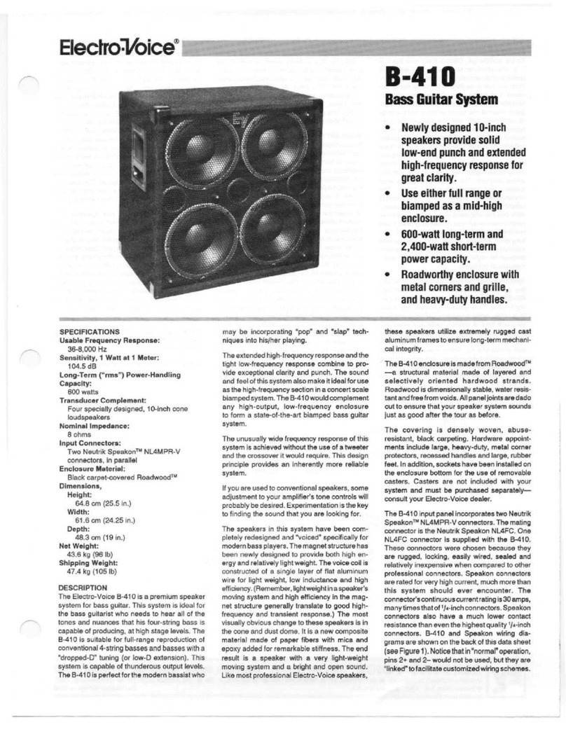
Electro-Voice B-410 User manual

Electro-Voice

Electro-Voice B-410 User manual

Electro-Voice ELX200-10P-US User manual

Electro-Voice

Electro-Voice ELX200-10P-US User manual

Electro-Voice 89478 User manual

Electro-Voice

Electro-Voice 89478 User manual

Electro-Voice Xi Series Xi-1082 User manual

Electro-Voice

Electro-Voice Xi Series Xi-1082 User manual

Electro-Voice Xi Series Xi-1152A/64F Manual

Electro-Voice

Electro-Voice Xi Series Xi-1152A/64F Manual

Electro-Voice ZxA5-90 User manual

Electro-Voice

Electro-Voice ZxA5-90 User manual

Electro-Voice Very Compact Full-Range Speaker 3.2 User manual

Electro-Voice

Electro-Voice Very Compact Full-Range Speaker 3.2 User manual

Electro-Voice EVX-180A User manual

Electro-Voice

Electro-Voice EVX-180A User manual

Electro-Voice Plasma Series User manual

Electro-Voice

Electro-Voice Plasma Series User manual

Electro-Voice TL550D User manual

Electro-Voice

Electro-Voice TL550D User manual

Electro-Voice XLE191 User manual

Electro-Voice

Electro-Voice XLE191 User manual

Electro-Voice 205 Series User manual

Electro-Voice

Electro-Voice 205 Series User manual

Electro-Voice TX1152FM User manual

Electro-Voice

Electro-Voice TX1152FM User manual

Electro-Voice EVM-12L User manual

Electro-Voice

Electro-Voice EVM-12L User manual

Electro-Voice EBK1-M10-3PACK Quick start guide

Electro-Voice

Electro-Voice EBK1-M10-3PACK Quick start guide

Electro-Voice EVID S Series User manual

Electro-Voice

Electro-Voice EVID S Series User manual

Electro-Voice ZX1i Series User manual

Electro-Voice

Electro-Voice ZX1i Series User manual

Popular Speakers manuals by other brands

ACOUSTIC SOLUTIONS 4244051 instruction manual

ACOUSTIC SOLUTIONS

ACOUSTIC SOLUTIONS 4244051 instruction manual

Sandstrom S42SWLH13 instruction manual

Sandstrom

Sandstrom S42SWLH13 instruction manual

EDIFIER S1000W manual

EDIFIER

EDIFIER S1000W manual

Sonos One SL manual

Sonos

Sonos One SL manual

Turbosound TXD Series user manual

Turbosound

Turbosound TXD Series user manual

Bose Surround Speakers manual

Bose

Bose Surround Speakers manual

TRENDWOO Morgen user manual

TRENDWOO

TRENDWOO Morgen user manual

EDIFIER Spinnaker e30 user manual

EDIFIER

EDIFIER Spinnaker e30 user manual

Tronsmart T6 Plus Bluetooth user manual

Tronsmart

Tronsmart T6 Plus Bluetooth user manual

Mackie SRM350 2-WAY user manual

Mackie

Mackie SRM350 2-WAY user manual

Miccus eXtreme SPX7 user guide

Miccus

Miccus eXtreme SPX7 user guide

Philips MMS321 Specifications

Philips

Philips MMS321 Specifications

Indiana Line TESI Q owner's manual

Indiana Line

Indiana Line TESI Q owner's manual

Alto TS115 truesonic quick start guide

Alto

Alto TS115 truesonic quick start guide

SBS TTMONOSPEAKERBTK user manual

SBS

SBS TTMONOSPEAKERBTK user manual

INTEMPO InConcert user manual

INTEMPO

INTEMPO InConcert user manual

Fostex FT17H Specification sheet

Fostex

Fostex FT17H Specification sheet

German Maestro CONCEPT CC 6508 IV installation manual

German Maestro

German Maestro CONCEPT CC 6508 IV installation manual

manuals.online logo
manuals.online logoBrands
  • About & Mission
  • Contact us
  • Privacy Policy
  • Terms and Conditions

Copyright 2025 Manuals.Online. All Rights Reserved.