Electrodata ATS-5X User manual

Copyright 2015 Rev. 04/15
ATS-5X
User Manual
Networked Communication Solutions, LLC
Electrodata, Inc.

ATS-5X User Manual Page 2 of 44
Contents
1 Introduction ....................................................................................................................................................................3
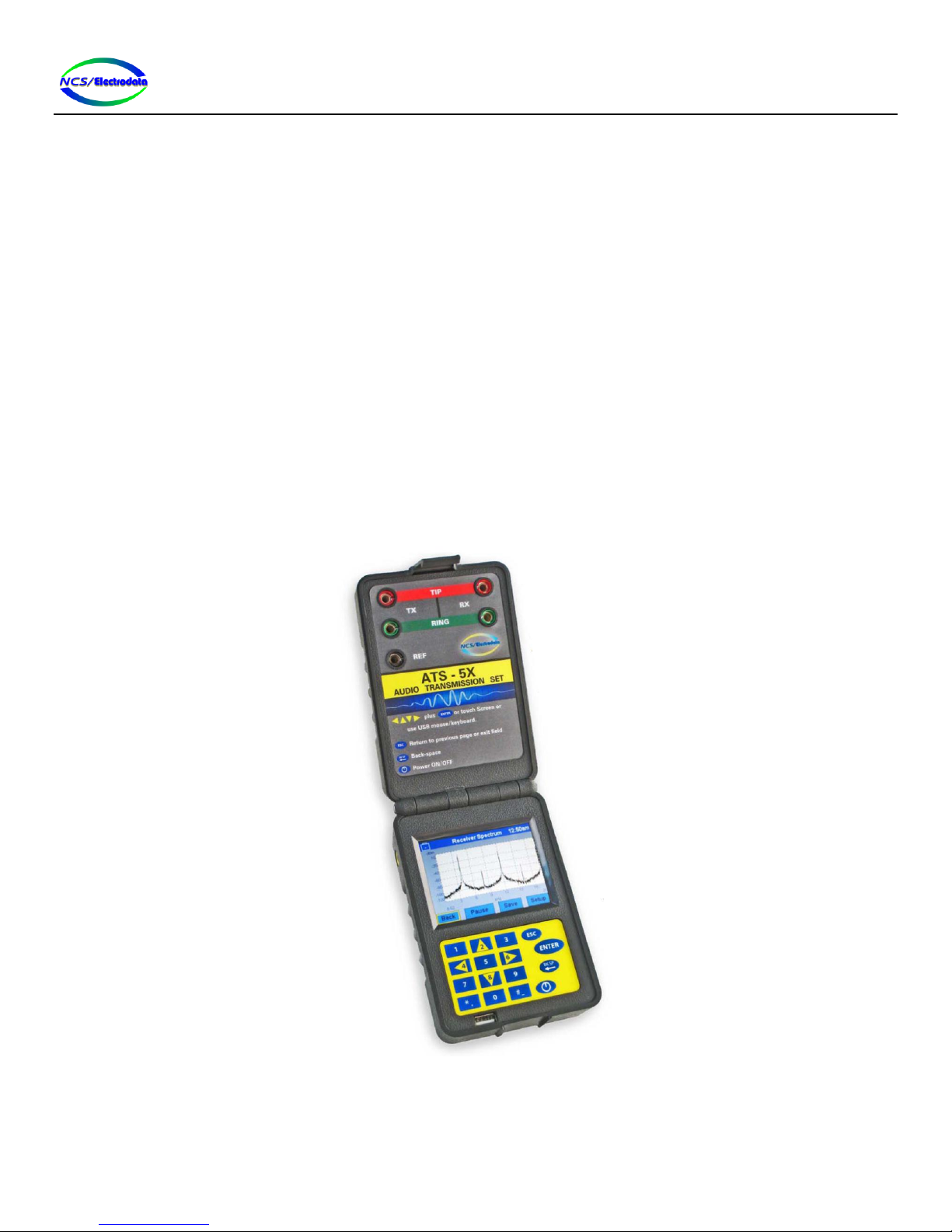
1.1 Overview .................................................................................................................................................................3
1.2 Interface.................................................................................................................................................................. 4
1.3 Assistance................................................................................................................................................................ 4
2 Operation........................................................................................................................................................................ 4
2.1 Instrument Power Up.............................................................................................................................................. 4
2.2 Battery Operation ................................................................................................................................................... 4
2.3 USB Devices............................................................................................................................................................. 4
2.3.1 Keyboard ......................................................................................................................................................... 4
2.3.2 Mouse ............................................................................................................................................................. 5
2.3.3 Combination Keyboard and Mouse ................................................................................................................5
2.3.4 Drive................................................................................................................................................................5
2.4 User Interface..........................................................................................................................................................6
2.4.1 Title Bar........................................................................................................................................................... 6
2.4.2 Control Selection............................................................................................................................................. 6
2.4.3 Screen Elements..............................................................................................................................................7
2.4.4 Screen Navigation .........................................................................................................................................12
2.5 Screens..................................................................................................................................................................13
2.5.1 Start-up Screen .............................................................................................................................................13
2.5.2 Main Menu....................................................................................................................................................13
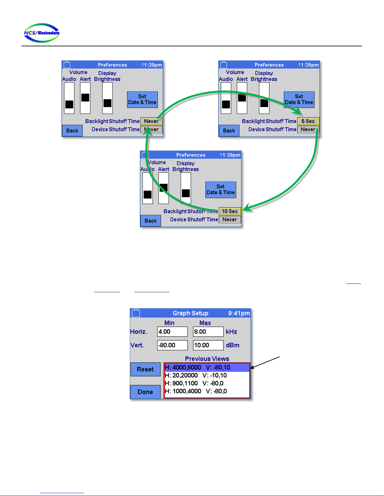
2.5.3 Preferences ...................................................................................................................................................13
2.5.4 Date & Time .................................................................................................................................................. 14
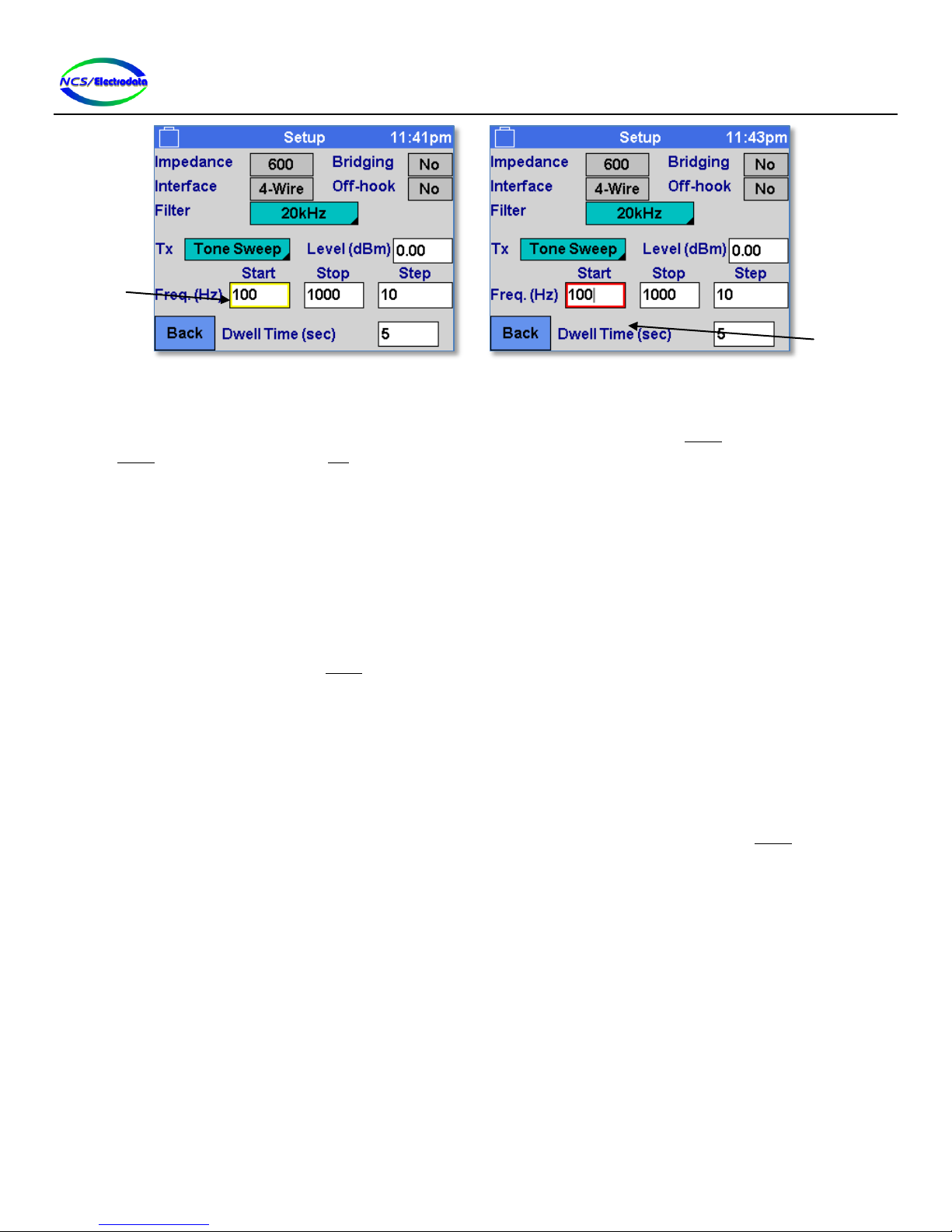
2.5.5 Setup .............................................................................................................................................................15
2.5.6 Self-Test......................................................................................................................................................... 18
2.6 Equipment Connection ......................................................................................................................................... 19
2.6.1 Longitudinal Balance.....................................................................................................................................19
2.6.2 Delay Emulation ............................................................................................................................................ 20
2.7 Measurements and Functions ..............................................................................................................................21
2.7.1 Level / Frequency / Noise .............................................................................................................................21
2.7.2 Impulse Noise................................................................................................................................................24
2.7.3 Longitudinal Balance.....................................................................................................................................25
2.7.4 Dialer.............................................................................................................................................................27
2.7.5 Delay Emulator (4-Wire) ...............................................................................................................................30
2.7.6 Echo Measurement....................................................................................................................................... 31
2.7.7 Spectrum....................................................................................................................................................... 33
2.7.8 23-Tone .........................................................................................................................................................33
2.7.9 P/AR Measurement.......................................................................................................................................34
2.7.10 Slope Measurement......................................................................................................................................35
3 Maintenance................................................................................................................................................................. 36
3.1 Software Update...................................................................................................................................................36
3.2 Calibration.............................................................................................................................................................37
3.3 Battery Care ..........................................................................................................................................................37
4 Specifications ................................................................................................................................................................38
5 Abbreviations................................................................................................................................................................ 43

ATS-5X User Manual Page 3 of 44
1Introduction
1.1 Overview
The ATS-5X is a hand-held test instrument for installation and troubleshooting of equipment or circuits in leased and
dial-up networks. Figure 1 below shows an image of the product in operation. The following measurements and
functions are provided:
Level, frequency and noise
Impulse noise
Longitudinal balance
23-tone
Slope
DTMF capture and dial interface
Spectrum display
Delay emulation
Echo measurement
Peak-to-average ratio
Figure 1 –ATS-5X Product Overview

ATS-5X User Manual Page 4 of 44
1.2 Interface
The test set interface is comprised of a color touchscreen LCD, a simple keypad and a USB port. The unit can be
controlled by the keypad, touchscreen or USB keyboard and mouse. The measurement data is shown on the display and
may be saved to a USB drive.
1.3 Assistance
Should you need assistance with the ATS-5X, please contact NCS/Electrodata at:
P.O. Box 31780
Independence, OH 44131
Local: (440) 374-4990
Fax: (440) 374-4994
Toll-free: 800-441-6336
Email: sales@ncs-electrodata.com
2Operation
2.1 Instrument Power Up
The ATS-5X has a display section and a measurement jack section that are joined by a hinge. To open the product for
normal use, release the locking tab opposite the hinge and separate the two halves of the product. Once separated,
press the power button on the keypad to turn the device on. The LCD that is above the keypad will immediately light up
and display the startup screen.
After the device is powered on, the start-up screen is displayed momentarily, and the results of a brief self-test are
displayed in the upper left-hand corner of the screen. If the self-test fails, the display will only show the start-up screen.
If the self-test passes, the display will show the Main Menu screen and the device is ready for use.
2.2 Battery Operation
The ATS-5X has an internal rechargeable battery that is not user replaceable. The battery is charged through the 12V
power adapter jack on the side of the ATS-5X. When the power adapter is powered and plugged into this jack, the
battery will be charged whether the ATS-5X is powered on or not. The power adapter may be inserted at any time into
the ATS-5X.
2.3 USB Devices
The ATS-5X has a USB host port and can support a single USB drive, keyboard and/or mouse. A keyboard or mouse can
be used to control the ATS-5X user interface, and a USB drive allows the user to save test results and update the ATS-5X
software. In the case that an unsupported device is plugged into the USB port, the ATS-5X will display a message
indicating the Vendor ID and Product ID of the unsupported device. USB hubs are not supported.
2.3.1 Keyboard
When a valid USB keyboard is plugged into the USB port, a keyboard icon will be displayed in the title bar to the right of
the battery (see Figure 2). The USB keyboard must be a class of USB device known as a human interface device (HID) in
order to be considered a valid keyboard. The keyboard keys listed below are valid control keys:
Keys that type a character
The directional arrow keys

ATS-5X User Manual Page 5 of 44
Enter
Backspace
Escape
Figure 2 –Keyboard Icon
2.3.2 Mouse
When a valid USB mouse is plugged into the USB port, a mouse icon will be displayed in the title bar to the right of the
battery (see Figure 3) and a cursor will be displayed on the screen. As with the keyboard, the mouse must be an HID
type device to be considered valid. The cursor can be moved by the mouse and pressing and releasing the left mouse
button will act the same as pressing and releasing the touchscreen at the point where the cursor is displayed on the
screen. If a selection list with scroll controls is active, rotating the mouse scroll wheel will scroll the list. Any other
mouse button is not a valid input.
Figure 3 –Mouse Icon
2.3.3 Combination Keyboard and Mouse
Some USB devices allow both a USB mouse and keyboard on the same connection point, such as wireless mice and
keyboards. These devices are considered valid as long as they are HID type.
2.3.4 Drive
When a valid USB drive is plugged into the USB port, a disk icon will be displayed in the title bar to the right of the
battery (see Figure 4). The USB drive must be a class of USB device known as a mass storage device and must be
formatted with a FAT32, FAT16 or FAT12 file system in order to be considered a valid drive. If a software update file is
on the drive, a message will be displayed asking if the ATS-5X software should be updated with the file.
Figure 4 –USB Drive Icon

ATS-5X User Manual Page 6 of 44
2.4 User Interface
NOTE: The user interface depicted in this manual is based on the operation of software version 1.15.
The screens shown on the touchscreen display have a number of different elements called controls to allow control of
the ATS-5X.The controls are similar to standard Microsoft Windows© control elements, such as buttons and selection
lists (see Figure 5).
Figure 5 –Sample Display
Interaction with the display controls is straightforward with the touchscreen or USB mouse. Using the keypad or USB
keyboard requires that controls be selected first prior to controlling them.
The various touchscreen displays have a number of common control elements that are used to setup the ATS-5X for
measurements. Interaction with the controls using the touchscreen or USB mouse is straightforward; however, most
actions using the keypad and USB keyboard require a control to be selected first.
2.4.1 Title Bar
Most screens show a title bar at the top of the screen to show the name of the current screen, the state of the battery
and the time. The state of the battery is indicated by different icons displayed on the left-hand side of the title bar.
These icons are described in Table 1 below.
Battery fully charged, power adapter plugged in
Battery charging
Battery discharging
Battery missing or damaged. Call factory for repair
(Flashing)
Battery charge is low
(Solid)
Battery is empty and device will automatically shut down
Table 1 –Battery Icons
2.4.2 Control Selection
To use the keypad and USB keyboard with a control element on the screen, the control must either be focused or active
in order to respond to keypad or keyboard input. A control is focused when it has a yellow perimeter and it is active
when it has a red perimeter (see Figure 6).
Button
controls

ATS-5X User Manual Page 7 of 44
Figure 6 –Focused and Active Controls
Focus is shifted from one control to the next by using the directional arrow keys on the keypad or USB keyboard. Once a
control is focused (yellow perimeter) it can be activated (red perimeter) by pressing the ENTER key and de-activated by
pressing ENTER again or by pressing the ESC key.
Some controls cannot be focused and must be controlled by the touchscreen or USB mouse. Only number or text entry
fields need to be activated before they can be controlled by the keypad or USB keyboard.
2.4.3 Screen Elements
2.4.3.1 Button Control
The button control element (see Figure 5 below) behaves similar to a standard button on a computer. An action is
initiated by pressing and releasing (touchscreen or USB mouse) within the boundary of the button. The button action
can also be performed by pressing the ENTER key when the button is focused.
2.4.3.2 Toggle Control
The toggle control allows selecting one action or setting from a collection. Each time the toggle control is pressed in the
same manner as a button control, the display text changes and a different action is performed. Each of the different
items available on the control can be accessed by successive control presses. The toggle control is demonstrated in
Figure 7 below.
A momentary toggle control, such as the 2713 Hz Burst control on the main menu, requires a holding action on the
touchscreen to remain activated. These types of controls may be toggled on and off by pressing the ENTER key.
Focused
Control
Active
Control

ATS-5X User Manual Page 8 of 44
Figure 7 –Toggle Control Item Cycling
2.4.3.3 Selection List Control
The selection list control displays a vertical list of text items and allows selection of one or more items, depending on the
context. The text items can be selected by pressing with the touchscreen or USB mouse on the item. To select an item
with the keypad or USB keyboard, the control must first be activated by focusing the control and then pressing the ENTER
key. Once activated, the UP ARROW and DOWN ARROW keys can be used to change the selected item. The selected item in
a selection list control is marked with a colored row, as shown in Figure 8.
Figure 8 –Selection List Control
2.4.3.4 Drop Selection List Control
The drop selection list control is similar to a selection list control in that it allows selection of a single item out of a
vertical list; however, the list collapses to show only the selected item when the selection is complete. The drop
selection list can be distinguished from the button and toggle controls by the marker in the bottom right hand corner, as
shown in Figure 9.
“Pressing” the toggle
control selects a new
list item
Selection List
Control

ATS-5X User Manual Page 9 of 44
To expand the list in order to make a selection, press the control in the same manner as a button control (see Figure 9).
Once the selection list is visible, the current selection row should be marked with a unique color in the same manner as
the selection list control. To change the selected item using the keypad or USB keyboard, press the up arrow and down
arrow keys. To change the selected item using the touchscreen or USB mouse, simply press the text to be selected, in
the same manner as the selection list control. The USB mouse scroll wheel may also be used to change the list selection.
Some lists have many items and show scroll controls on the right side of the list to allow viewing all of the selections (see
Figure 10). To use the scrolling feature on the list, press the up and down arrow buttons with the touchscreen or USB
mouse.
Once the selection has been made, it must be confirmed in order to hide the selection list and perform the associated
action or setting change. To do this with the keypad or USB keyboard, press the ENTER key. To confirm the selection
with the touchscreen or USB mouse, press the item a second time or press somewhere outside of the boundary of the
selection list. Cancel a selection change by pressing the ESC key with the selection list visible.
Figure 9 –Drop Selection List Control, Collapsed and Expanded
Figure 10 –Drop Control with Scroll Buttons
2.4.3.5 Grid Control
A grid control allows selection of data items outlined in a table format (see Figure 11). The grid control cannot be
focused and therefore cannot receive keypad or USB keyboard input. A grid control may allow a single selection,
multiple selections or only a momentary selection (selection made while pressed). As with the button control, the
selection must be made by pressing and releasing within the bounds of a single grid cell.
Drop control
in collapsed
form
Drop control
in expanded
form

ATS-5X User Manual Page 10 of 44
Figure 11 –Grid Control
2.4.3.6 Text Entry Control
The text entry control provides a means of specifying text as numbers and letters (see Figure 12). The control must first
be activated to enter or change the text. Using the touchscreen or USB mouse, this is accomplished by simply pressing
the within the boundary of the field. Using the keypad or USB keyboard, the control can be activated by pressing the
ENTER or BK-SP keys when the control is focused. Pressing the BK-SP key to activate the focused control will cause the
existing contents of the control to be cleared.
Once activated, modification of the text occurs at the location of the blinking cursor, in the same manner as on a
computer. The cursor position may be moved by pressing the LEFT ARROW and RIGHT ARROW keys on a USB keyboard.
Pressing the BK-SP key with the control activated will cause of the removal of one character to the left of the cursor.
Pressing a valid key will cause the insertion of a character at the location of the cursor. If the character to the right of
the cursor is a number, pressing the UP ARROW and DOWN ARROW keys on a USB keyboard will increment and decrement
that digit.
A text entry control may have limits on the number and type of characters allowed. Text entry controls that allow only
numbers may be configured to ensure that the number is within maximum and minimum values. Pressing the #- key for
a number-only text entry that allows negative numbers will toggle the sign of the number, regardless of cursor position.
To cancel changes made to the control text while activated, press the ESC key. To commit changes made to the control
text, press the ENTER key or press outside of the control boundary with the touchscreen or USB mouse.
Figure 12 –Text Entry Control
2.4.3.6.1 On-Screen Keyboard
To allow text entry with the touchscreen or USB mouse, press and hold within the boundary of the text entry control.
This will display an on-screen keyboard, such as shown in Figure 13.Characters that are selected on the grid control will
be displayed in the text entry control at the top of the screen. The functionality of the buttons is defined as follows:
Grid control
circled
Text Entry
Control

ATS-5X User Manual Page 11 of 44
Bksp: Backspace –delete the character to the left of the cursor in the text entry field at the top of
the screen
(Left arrow): Move the text entry field cursor one character to the left
(Right arrow): Move the text entry field cursor one character to the right
Space: Insert a blank space character at the cursor location in the text entry field
DONE: Accept the changes made to the text
The functionality of the toggle controls is defined as follows:
abc/ABC: Toggle capitalization of the letters within the grid control
(0-9) Symbols/Letters: Toggle the character set of the grid control
Figure 13 –On-Screen Keyboard
2.4.3.7 Slider Control
The slider control allows visual adjustment of a setting (see Figure 14). The slider control cannot be focused and
therefore cannot receive keypad or USB keyboard input. To adjust the slider setting, use the touchscreen or USB mouse
to momentarily press within extents of the control to bring the slider set-point to the center of the pressed location. To
continuously adjust the slider set-point, press and hold within the control boundary, moving the touchscreen press
location or USB mouse while holding.
Figure 14 –Slider Control
2.4.3.8 Graph Display
The graph display shows a sequence of data points connected by lines (see Figure 15). Unless otherwise disabled, the
graph display can be focused and activated for keypad or USB keyboard input. Once activated, pressing the UP ARROW or
DOWN ARROW keys will change the vertical axis limits so that current “view” of the data is shifted either up or down.
Slider
Controls

ATS-5X User Manual Page 12 of 44
Similarly, the RIGHT ARROW and LEFT ARROW keys shift the horizontal axis limits so that the data view moves right and left.
The graph axis limits may only be adjusted with the keypad or USB keyboard if the axis values are not already at their
limits.
Figure 15 –Graph Display
2.4.3.8.1 Graph Display Limit Adjust
To adjust the horizontal and vertical axis values of the graph display, press and hold (touchscreen or USB mouse) within
the boundary of the graph display for at least 1 second. This will display the Graph Setup screen (see Figure 16). Four
number entry fields are shown to adjust the minimum and maximum horizontal and vertical axis limits. The Reset
button will adjust the axis limits in the four number entry fields back to their default values. The Done button hides the
Graph Setup screen and shows the original graph display with the axis limits specified in the Graph Setup screen. Select
an item in the Previous Views selection list to quickly restore a common display setting.
Figure 16 –Graph Setup Screen
2.4.4 Screen Navigation
There are controls on each screen that allow the user to change to other screens. For instance, most screens have a
Back button that returns the display to the previous screen. When the ATS-5X is first powered on, the Start-Up screen is
displayed momentarily and then the Main Menu screen is displayed. From this point, the Setup or System Menu screens
may be displayed by pressing their respective buttons on the Main Menu screen, or the displayed may be moved to one
of the measurement screens by pressing one of the measurement buttons. Pressing the ESC key will return the display
to the previous screen. Figure 17 below shows a simplified diagram of the screen navigation.
Graph
Display
Top border color
indicates if display
is focused or active
Horizontal
axis units
Vertical
axis units

ATS-5X User Manual Page 13 of 44
Figure 17 –Simplified Screen Navigation Diagram
2.5 Screens
2.5.1 Start-up Screen
After the ATS-5X is powered on, a splash screen is displayed while loading. This screen shows the results of the power-
on self test in the upper left-hand corner, the product serial number in the lower left-hand corner and the software
version in the lower right-hand corner. After the initialization is complete, the Main Menu screen is automatically
displayed. To allow the start-up screen to be displayed indefinitely, press the Freeze toggle control. Press it again to
continue to the main screen.
2.5.2 Main Menu
The Main Menu screen (see Figure 17) allows access to each of the measurement functions, to the System Menu screen
and the Setup screen. The 2713 Hz Burst momentary toggle control allows a momentary override of the transmitter
setup to transmit a 2713 Hz tone at 0 dBm. When the control is active, the tone is transmitted. Once the control is de-
activated, the transmitter is disabled.
2.5.3 Preferences
The Preferences screen can be accessed from the Main Menu screen by pressing the System Menu button and then the
Preferences button. This screen allows adjustment of ATS-5X parameters related to the user interface, as shown in
Figure 18 below.

ATS-5X User Manual Page 14 of 44
Figure 18 –Preferences Screen
The screen controls have the following function:
Audio Volume: Adjusts the volume of the ATS-5X receive signal, which may be the signal at the receive jack
or the transmit jack, depending on the configuration in the Setup screen. Moving the slider
towards the top of the screen will increase the volume.
Alert Volume: Adjusts the volume of the user interface alerts or “beeps.”
Display Brightness: Adjusts the intensity of the display backlight. Moving the slider toward the top of the screen
will increase the brightness.
Backlight Shutoff Time: Sets the inactivity duration before the display brightness level is reduced. User interface
operation will maintain the display brightness at the set level. However, after a period of
inactivity, the display brightness will be reduced. User interface operation will again restore
the brightness back to the set level. This setting may be used to assist in prolonging the
battery charge.
Device Shutoff Time: Sets the inactivity duration before the ATS-5X will power down. Unless there is user
interface activity within the specified duration, the device will shut itself down.
Set Date & Time: Displays the Date & Time screen to allow adjustment of the date and time.
2.5.4 Date & Time
The time and date that is maintained by the ATS-5X may be adjusted from the Date & Time screen, accessible from the
Preferences screen. Figure 19 below shows the date and time adjustment.
Figure 19 –Date & Time Screen
Hours
Minutes
Seconds
Year
Day

ATS-5X User Manual Page 15 of 44
2.5.5 Setup
The Setup screen allows configuration of the ATS-5X line interface. Although Figure 22 shows one example of a
configuration, the content and available selections on the screen are dependent upon the measurement mode
previously selected. The ATS-5X line interface is influenced by the setup options as shown in Figure 20 and Figure 21.
Figure 20 –Line Interface Options (4-Wire Configuration)
Source Z / 2
Tx Source Z / 2
Termination Z
Rx
TIP
RING
TIP
RING
Interface:
Bridging:
Transmitter:
4-Wire
Off
On
SETTINGS
Transmitter
Receiver
Source Z / 2
Tx Source Z / 2
Tx
Rx
TIP
RING
TIP
RING
Interface:
Bridging:
Transmitter:
4-Wire
On
On
SETTINGS
Transmitter
Receiver
Source Z / 2
Source Z / 2
Termination Z
Rx
TIP
RING
TIP
RING
Interface:
Bridging:
Transmitter:
4-Wire
Off
Off
SETTINGS
Transmitter
Receiver
Rx
TIP
RING
TIP
RING
Interface:
Bridging:
Transmitter:
4-Wire
On
Off
SETTINGS
Transmitter
Receiver

ATS-5X User Manual Page 16 of 44
Figure 21 –Line Interface Options (2-Wire Configuration)
The setup options are listed below:
Impedance selection
o600: Selects a 600Ω source impedance for the transmitter and termination impedance for the receiver.
o900: Selects 900Ω source and termination impedances in the same manner as the 600Ω selection.
Bridging selection
oNo: Transmitter has the specified source impedance and receiver has the specified termination
impedance.
oYes: Transmitter (when not in use) and receiver are high-impedance.
Interface selection
o2-Wire: The receiver is connected to the transmit jack tip and ring.
o4-Wire: The receiver is connected to the receive jack tip and ring.
Source Z / 2
Tx Source Z / 2
Rx
Interface:
Bridging:
Transmitter:
2-Wire
On of Off
On
SETTINGS
TIP
RING
Transmitter
TIP
RING
Receiver
Source Z / 2
Source Z / 2
Rx
Interface:
Bridging:
Transmitter:
2-Wire
Off
Off
SETTINGS
TIP
RING
Transmitter
TIP
RING
Receiver
Rx
Interface:
Bridging:
Transmitter:
2-Wire
On
Off
SETTINGS
TIP
RING
Transmitter
TIP
RING
Receiver

ATS-5X User Manual Page 17 of 44
Off-hook selection
oNo: A telephone on-hook condition is presented to the transmit jack tip and ring.
oYes: A telephone off-hook condition is presented to the transmit jack tip and ring.
Tx selection
oOff: The transmitter is disconnected from the transmit jack.
o1004 Hz: A single 1004 Hz tone at 0 dBm
oSingle Tone: A single sinusoidal tone with the specified Level (dBm) and Freq. (Hz)
oTone Sweep:A single sinusoidal tone with the specified Level (dBm) and variable frequency
o23-tone: 23 simultaneous tones at frequencies between 150 Hz and 4 kHz. The combined signal level is
specified with the Level (dBm) number entry.
oP/AR: (Peak-to-Average Ratio signal) 16 simultaneous tones at frequencies between 140 Hz and 4 kHz.
The combined signal level is specified with the Level (dBm) number entry.
oSlope: A single tone with the specified Level (dBm) and variable frequency. While in the applicable -
measurement screens, the frequency of the transmit tone will cycle among 404 Hz, 1004 Hz and
2804 Hz indefinitely with a 10 second dwell at each frequency.
Filter selection
o20 kHz: No additional attenuation is applied to the receiver
oC-Msg.: C-Message weighted filter
o3.4kHz Flat: A low-pass filter with 3.4 kHz cutoff frequency
oD Filter: A band-pass filter between 300 Hz and 3.4 kHz
o15kHz Flat: A low-pass filter with 15 kHz cutoff frequency
o1010Hz Notch: A band-stop filter with 1010 Hz center frequency, providing at least 50dB attenuation between
995 and 1025 Hz.
oC-msg. Notch: The combination of a C-message filter and a 1010Hz notch filter
Level (dBm) adjustment
oSpecifies the level of the transmitted signal in dBm.
Freq. (Hz) adjustment
oSpecifies the frequency for single-tone transmitter selections
Start adjustment
oSpecifies the start frequency (in Hertz) for a single-tone frequency sweep
Stop adjustment
oSpecifies the stop frequency (in Hertz) for a single-tone frequency sweep
Step adjustment
oSpecifies the frequency increment (in Hertz) for a single-tone frequency sweep
Dwell Time (sec) adjustment
oSpecifies the amount of transmission time at each frequency increment during a single-tone frequency sweep.
All changes in the Setup screen occur immediately. The tone frequency will remain constant within the Setup screen
when the Tone Sweep and Slope transmitter selections. These selections require use of their respective measurement
screens to automatically change the frequency.
When the setup context is changed by selecting a different measurement, some settings that were valid for the previous
measurement may not be valid for the current measurement. If this is the case, any invalid settings will be changed to
valid settings when the new measurement or function is chosen. For this reason, it is a good practice to verify the setup
for each new measurement used.
When the display shows any screen other than the measurement or function screen, or the Setup screen, the setup is
changed so that the transmitter is set to off. Therefore, if the transmitter is set to single tone in the Setup screen and

ATS-5X User Manual Page 18 of 44
the display is navigated to the Main Menu screen, the transmitter will be set to off and will remain off until it is set again
in the Setup screen.
When finished with the setup, press the Back button to return to the previous screen.
Figure 22 –Setup Screen
2.5.6 Self-Test
The ATS-5X has a self-test functionality to allow the user to verify proper operation. The Self-Test screen can be
accessed by pressing the Self-Test button on the System Menu screen. This will begin a sequence of tests that require
user interaction. Tests may be skipped to check the operation of certain functions.
The instructions for each test will be displayed on the screen. Respond to each prompt within 1 minute, or the self-test
will be aborted. After completion of the self-test, a summary is displayed, showing the results for each of the tests, as
shown in Figure 23 below. If the self-test was aborted due to prolonged inactivity, the test result will be “Untested.”
Figure 23 –Self-Test Results
The following controls are displayed on the Self-Test screen at various points:
Back: Return to the previous screen
Yes: Affirmative answer to the prompt on the screen
No: Negative answer to the prompt on the screen
Retry: Repeat the test and discard the results of the last test.
Again: Repeat the entire self-test

ATS-5X User Manual Page 19 of 44
2.6 Equipment Connection
The ATS-5X has a differential transmitter with a two terminal jack and a receiver with the same configuration. When
Interface is specified as 2-wire in the Setup screen, the internal receiver is connected to the transmitter jacks and the
receiver jacks are not used (see Figure 21). When Interface is specified as 4-wire, the receiver is connected to the
receiver jacks and both sets of jacks are used for testing (see Figure 20).
The ATS-5X can be used for in-service tests, end-to-end tests or loop tests. However, there are some special setup
considerations for some ATS-5X functions.
2.6.1 Longitudinal Balance
The longitudinal balance measurement applies a common mode signal to the tip and ring of the transmitter relative to
the reference jack. When using the longitudinal balance measurement, the reference jack should be connected to a
potential for which balance is to be measured. In most cases, this is simply ground or the cable shield. For all other ATS-
5X measurements, the reference jack should not be connected. The source impedance of the transmitter is fixed at
365Ω nominal for both the tip and ring connections.
The longitudinal balance is computed from two separate measurement configurations. The first measurement
configuration has the circuit under test connected to the tip and ring of the ATS-5X transmitter jack as shown in Error!
Reference source not found.. The second measurement configuration requires the circuit under test to be connected to
the ATS-5X transmitter jack in reverse fashion, as shown in Figure 25.
The longitudinal balance measurement should be conducted on a circuit that is not in service and with the far-end
equipment is not generating any signal near the test frequencies of the ATS-5X.
Figure 24 –Longitudinal Balance Setup –Step 1 (Normal Connection)
TIP
RING
Transmitter
Z
Tx Z
REF
ATS-5X
Rx TIP
RING
Receiver
Terminating
Equipment
Shield or Ground

ATS-5X User Manual Page 20 of 44
Figure 25 –Longitudinal Balance Setup –Step 2 (Reversed Connection)
2.6.2 Delay Emulation
The delay emulation function serves as a unidirectional repeater with adjustable delay and attenuation. This
functionality may be used to simulate mid-span delay or echo from a far-end device. The ATS-5X must be connected in a
4-wire manner in either configuration. The repeater configuration is as shown in Figure 26 and the far-end configuration
is as shown in Figure 27.
Figure 26 –Delay Emulator Mid-Span Repeater Setup
TIP
RING
Transmitter
Z
Tx Z
REF
ATS-5X
Rx TIP
RING
Receiver
Terminating
Equipment
Shield or Ground
Source Z / 2
Tx Source Z / 2
TIP
RING
Transmitter
Termination Z Rx
TIP
RING
ATS-5X
Receiver
End Device End Device
Tx
Rx
Rx
Tx
Table of contents
Popular Test Equipment manuals by other brands

System Sensor
System Sensor RTS151KEY Installation and maintenance instructions

Agilent Technologies
Agilent Technologies U1602B quick start guide

Amprobe
Amprobe AMB-45 user manual

Viking
Viking 58759 Owner's manual & safety instructions

ETCR
ETCR 3000 manual

Hanna Instruments
Hanna Instruments Pool Line HI983044 instruction manual

PCE Health and Fitness
PCE Health and Fitness PCE-900 user manual

Telegärtner
Telegärtner UCT9 operating instructions

Agilent Technologies
Agilent Technologies MSO8104A Service note

AquaLabo
AquaLabo ORCHIDIS FLOTTATEST user manual

TiePie
TiePie Handyscope HS5 series user manual

Würth
Würth 0715 53 325 Translation of the original operating instructions