Sper scientific 420001 User manual

Electrical Insulation
Tester
420001

2
SAFETY INFORMATION
Read the following safety information carefully before
attempting to operate or service the meter.
To avoid damages to the instrument do not apply the signals
which exceed the maximum limits shown in the technical
specifications tables.
Do not use the meter or test leads if they look damaged. Use
extreme caution when working around bare conductors or bus
bars.
Accidental contact with the conductor could result in electric
shock.
Use the meter only as specified in this manual; otherwise, the
protection provided by the meter may be impaired.
Read the operating instructions before use and follow all
safety Information.
Caution when working with voltages above 60V DC or 30V AC
RMS. Such voltages pose a shock hazard.
Before taking resistance measurements or testing acoustic
continuity, disconnect circuit from main power supply and all
loads from the circuit.

3
Safety symbols:
Caution refer to this manual before using the meter.
Dangerous voltages.
Meter is protected throughout by double insulation or
reinforced insulation.
When servicing, use only specified replacement parts.
CE Comply with EN-61010-1
1. SPECIFICATIONS
1-1 General Information
Environment conditions:
①
①
Installation CategoriesⅢ
②
②
Pollution Degree 2
③
③
Altitude up to 2000 meters
④
④
Indoor use only
⑤
⑤
Relatively humidity 80% max.
⑥
⑥
Operation Ambient 0~40ºC
Maintenance & Clearing:
①
①
Repairs or servicing not covered in this manual should only be
performed by qualified personnel.
②
②
Periodically wipe the case with a dry cloth. Do not use
abrasives or solvents on this instruments.
Display: Large LCD with dual display
Measurement Range: 4000MΩ/125V, 4000MΩ/250V,
4000MΩ/500V, 4000MΩ/1000V, 400Ω/BZ,

4
1000V/DCV. ,750V/ACV
Sampling Rate: 2.5 times per second.
Zero Adjustment: Automatic adjustment.
Over Range Indicator: “OL”of highest digit is displayed.
Low Battery Indication: The is displayed when the battery
Voltage drop below the operating voltage.
Operating Temperature: 0ºC to 40ºC (32ºF to 104ºF) and Humidity
below 80% RH
Storage Temperature: -10ºC to 60ºC (14ºF to 140ºF) and Humidity
below 70% RH
Power source: DC9V (6x1.5V Size “AA” battery or Equivalent)
Dimensions: 200(L) x 92(W) x 50(H) mm
Weight: Approx 700g include battery
Accessories: Test leads, 6pcs battery, Carrying case, manual.
1-2 Electrical Specifications
Accuracies are specified in the way:
±(…% of reading +…digits) at 23ºC±5ºC,below 80% RH.
OHMS
Range Resolution Accuracy Max. open
Circuit Voltage
Overload
Protection
40.00Ω
0.01Ω
+(1.2%+3)
5.8V
250Vrms
400.0Ω0.1Ω5.8V
Continuity Beeper
Range Resolution Operation
Resistance
Max.open
Circuit
Voltage
Overload
Protection

5
•))) 0.01ΩResistance≤35Ω5.8V 250Vrms
Short circuit current
≧
200mA
DC Voltage
Range Resolution Accuracy Input
Impedance
Overload
Protection
1000V
1V
+(0.8%+3)
10MΩ
1000Vrms
AC Voltage (40Hz~400Hz)
Range Resolution Accuracy Input
Impedance
Overload
Protection
750V
1V
+(1.2%+10)
10MΩ
750Vrms
Meg OHMS
Terminal
Voltage
Range Resoluti
on
Accuracy Test
Current
Short
circuit
current
125V(0
%~+10
%)
0.125~4.000 MΩ
0.001MΩ
+(2%+10)
1mA
@load
125kΩ
≤1mA
4.001~40.00 MΩ
0.01MΩ
+(2%+10)
40.01~400.0 MΩ
0.1MΩ
+(4%+5)
400.1~4000 MΩ
1MΩ
+(5%+5)
250V
(0%~+1
0%)
0.250~4.000 MΩ
0.001MΩ
+(2%+10)
1mA
@load
250kΩ
≤1mA
4.001~40.00 MΩ
0.01MΩ
+(2%+10)
40.01~400.0 MΩ
0.1MΩ
+(3%+5)
400.1~4000 MΩ
1MΩ
+(4%+5)
500V(0
%~+10
%)
0.500~4.000 MΩ
0.001MΩ
+(2%+10)
1mA
@load
500kΩ
≤1mA
4.001~40.00 MΩ
0.01MΩ
+(2%+10)
40.01~400.0 MΩ
0.1MΩ
+(2%+5)

6
400.1~4000 MΩ
1MΩ
+(4%+5)
1000V
(0%~+1
0%)
1.000~4.000 MΩ
0.001MΩ
+(3%+10)
1mA
@load
1MΩ
≤1mA
4.001~40.00 MΩ
0.01MΩ
+(2%+10)
40.01~400.0 MΩ
0.1MΩ
+(2%+5)
400.1~4000 MΩ
1MΩ
+(4%+5)
2. PARTS & CONTROLS
1.Digital Display
2.Data Hold Button; MAX/MIN
3.Lock Button
4.Backlight Button; ZERO
5.Test Button
6.Rotary Function switch
7.VΩJack
8.COM input jack
9. Pothook
10.Battery Cover
2-1 How to connect test leads.
On MΩRange , and 400Ω/BZ ,ACV,. DCV, Connect the red test
lead into the “VΩ” terminal and the black lead into the “COM”
terminal.
2-2 Battery Check-UP & Replacement
a) As battery power is not sufficient. LCD will display .
Replacement of 6 pcs new batteries, type 1.5V size “AA” is
Required.
b). Place back the battery cover and four the screws.
2-3 Test leads check
Set the range select switch to the 400Ωrange. With the tip and
750V
1000V
Insulation Tester
400
125V
250V
500V
1000V
TEST
LOBAT HV
(1)
POL1
(2)
(1)
OHM
BZ
(2)
(2)
POL2
4
(1)
BAR
1
85
1
2
3
4
6
78
9
10
CEM
DT-5505
5

7
alligator clip of the test leads connected. The indicator should read
00.0Ω. When the leads are not connected the display will read
infinity indicated by “OL”. This will ensure that test lead are under
working condition.
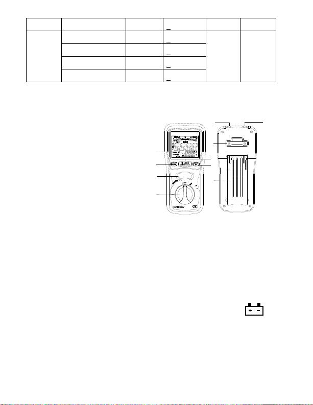
2-4 Rotary Switch positions
Turn the Tester on by selecting any measurement
Lift <1000v,500v,250v,125v (4000MΩ)
OFF 400Ω/BZ, 1000VDC,750VAC >Right
2-5 Buttons and a display Indicators
a). Button
HOLD/MAX.MIN : Instant-pressing the “HOLD”button the 1st time,
the current values will be hold in the primary display., but it will return
in the 2nd pressing ; pressing 2 seconds ,it will enter directly into the
“MAX”status, and one another instant-pressing will switch to the
“MIN”, if instant-pressing once more, it will recycle ,but exit if
pressing 2 seconds again.
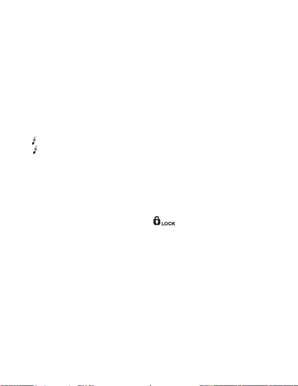
LOCK :In the insulation resistance testing function ,press the
“LOCK”button ,and then push down the “TEST”key, it will occur the
high-voltage and enter the insulation resistance testing status. Press
the “TEST”button once more ,it will shutoff the high-voltage and exit
from the insulation resistance testing status.
TEST : In the insulation resistance testing function ,pressing and
holding the “TEST”button, The meter will bring high-voltage, and
enter into the insulation resistance testing, being free from the
“TEST”, it will cutoff the high-voltage and exit form the insulation
resistance testing.
ZERO/LIGHT :Iinstant-pressing the “ZERO/LIGHT”button in the 1st
time, the current values in the primary display will be set
zero,(mainly used for 400Ω, the low resistance testing), ,it will return

8
if in the 2nd time. pressing for 2 seconds, it will enter directly into the
“LIGHT”status, and the LCD backlight light up. After 15 seconds, the
backlight is shut off automatically, the same as pressing for 2
seconds within 15s.
b) Display Indicators
The Primary Display:Indicate the current function testing values
The Secondary Display:It shows the output DCV while you test the
insulation resistance, and the battery voltage while the ACV
The Analog Bar :indicate the current function testing value in
synchronous with the primary display.
:While testing the insulation resistance, the symbol
““flashes frequently if the voltage is over 30V.
•))) : While testing the insulation resistance, the symbol”•)))
“flashes frequently and the buzzer warns continually if the
outside voltage is over 30V. the symbol “•))) “is indicated
while LOΩ≤35Ωand the BZ warns continuously.
LOCK:
:
Push down the “LOCK”button while you test the insulation
resistance and the symbol “”is indicated.
LOBAT:The display shows “LOBAT”when the voltage
drops below 7.5V
MAX/MIN:Stand for the maximum or the minimum.
ZERO : Digital zero adjusting。
HOLD :The digital holding function for the primary display.
AC,
,
DC,
,
:The indicator for the voltage property.
V,
,
MΩ,
,
ΩThe measured dimension units。

9
3. INSULATION RESISTANCE MEASUREMENTS
a)Turn the function switch from the “OFF”position to the left(4000
MΩ/1000V---4000/ MΩ500V---4000 MΩ/250V---1000
MΩ/125V),and chose one of the voltage-block( there are 4 ranges
namely, 4 MΩ40 MΩ400 MΩ4000 MΩ, can be switched
automatically for every voltage-block.)
b)Connect two testing lines to the tested;
c)Push down and hold the “TEST”button /or press the “LOCK”
keystoke first and then the “TEST”button, if the tested is
electriferous and its voltage ( AC/DC) is over 30V, it will refuse
work and no high-voltage testing occurs, simultaneity, it shows
“>30V”on the LCD, the symbol “”flashes, and the buzzer
warns frequently. if the tested is diselectriferous or its voltage is
lower than 30V, it will enter into the formal testing process and
brings the high-voltage. on the primary display, the insulation
resistance in MΩis indicated in-phase with analog bar; on the
secondary display, the tested insulation voltage in V (DC) is
indicated, the symbol “”flashes and the buzzer warns
frequently
d)Being free from the “TEST”button or pushing down the “TEST”
button in the “LOCK “status can exit from the “LOCK”status and
shutoff the high-voltage,synchronously, the resistance values is
indicated in the primary display will be held, and the secondary
display still be in the status of monitoring the insulation voltage for
the tested.
e)Subsequently, discharge the balance insulation voltage of the
tested through the inner switch of the meter.
Turning the function switch can exit automatically from testing
status during the process。

10
4.LOW RESISTANCE (CONTINUITY)
MEASUREMENTS
a). Set the range switch to 400Ω/BZ Position
b). Connect the red test lead to the V Ωterminal and black to the
COM terminal.
c). Connect the tips of the test leads to both ends of the circuit under
test. read resistance in Ωon the LCD. The two
ranges(40.00/400.0Ω) can be switched automatically; the
primary display of the resistance in Ω, flashes in synchronous
with the analog bar.
d). When the impedance on circuit is below approximately ≤35Ω.It
will indicate by a continuous beeper.
e) The current is from 200 to 220mA while the tested resistance is
0Ω
f) The high voltage symbol “ “flashes along with a primary
display of “>30V” and the buzzer warns frequently if the voltage
(AC/DC) is more than 30V.
5.AC/DC VOLTAGE MEASUREMENTS
a). Set the range switch to ACV or DCV position
b). Connect red test lead to “V Ω” terminal and black test lead to
terminal “COM”.
c). Connect test prods of test leads IN PARALLEL to the circuit being
measured.
d). Read the voltage value on LCD.

11
6.BATTERY SAVER (SLEEP MODE)
The meter will automatically enter the “sleep mode”if there is no
function change or button press for 10minutes, but it works as soon
as you turn the rotary function switch or push down any button.
7.POWER TOOLS AND AMALL APPLIANCES
This test would also apply to other similar equipment that has a line
cord. For double insulated power tools, the megohmmeter lead
shown connected to the housing would be connected to some metal
part lf the tool(e..g chuck,blade).
Note: The switch of the device must be in the “ON” position and the
main power should be disconnected.
MOTORS
AC-Disconnect the motor from the line by disconnecting the wires at
the motor terminals or by opening the main switch. If the main switch
is used and the motor also has a starter then the starter must be
held, by some means, in the “ON” position. In the latter case, the
measured resistance will include the resistance of the motor, wire
and all other components between the motor and the main switch. If
a weakness is in dicated, the motor and other components should
be checked individually. If the motor is disconnected at the motor
terminals, connect one megohmmeter lead to the grounded motor
housing and the other lead to One of the motor leads.
DC-Disconnect the motor from the line. To test the brush rigging,
field coils and armature connect one megohmmeter lead to the
grounded motor housing and the other lead to the brush on the
commutator. If the resistance measurement indicates a weakness,
raise the brushes off the commutator and separately test the

12
armature, field coils and brush rigging by connecting one
megohmmeter lead to each of them individually, leaving the other
connected to the grounded motor housing. The above also applies
to DC Gemerators.

13
CABLES
Disconnect the cable from the line. Also disconnect opposite end to
avoid errors due to leakage from other equipment. Check each
conductor to ground and /or lead sheath by connecting one
megohmmeter lead to a ground and /or lead sheather and the other
megohmmeter lead to each of the conductors in turn. Check
insulation resistance between conductors by connecting
megohmmeter leads to conductors in pairs.

WARRANTY
Sper Scientic warrants this product against defects
in materials and workmanship for a period of one (1)
year from the date of purchase, and agrees to repair
or replace any defective unit without charge. If your
model has since been discontinued, an equivalent
Sper Scientic product will be substituted if available.
This warranty does not cover probes, batteries, battery
leakage, or damage resulting from accident, tampering,
misuse, or abuse of the product. Opening the meter to
expose its electronics will break the waterproof seal and
void the warranty.
To obtain warranty service, ship the unit postage
prepaid to:
SPER SCIENTIFIC LTD.
8281 East Evans Road, Suite #103
Scottsdale, AZ 85260
The defective unit must be accompanied by a
description of the problem and your return address.
Register your product online at www.sperwarranty.com
within 10 days of purchase.
Table of contents
Other Sper scientific Test Equipment manuals
Popular Test Equipment manuals by other brands

HTC
HTC CE8200 user manual

Kenwood
Kenwood CS-5230 Service manual

Keysight Technologies
Keysight Technologies E7515A Getting started guide

PAS Systems International
PAS Systems International PAS Vr. Alcohol Screening & Verification... instruction manual

Hioki
Hioki IR4055 instruction manual

LeCroy
LeCroy WaveAce series Getting started manual

Parker Research Corp
Parker Research Corp B300-MR Series operating instructions

Time Electronics
Time Electronics 1024 user manual

Sealey
Sealey VS0275.V2 instructions

Tektronix
Tektronix 511 instruction manual

Monacor
Monacor LED-300DX/WS instruction manual

Agilent Technologies
Agilent Technologies N4413A user guide