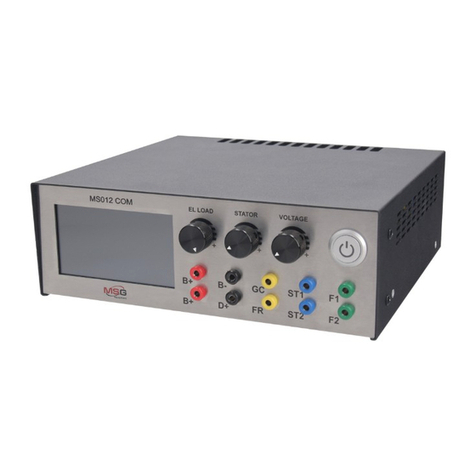
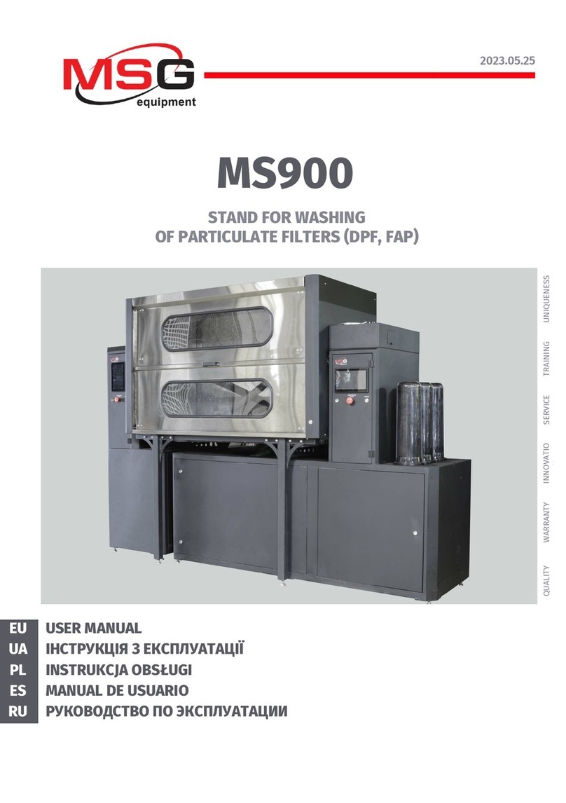
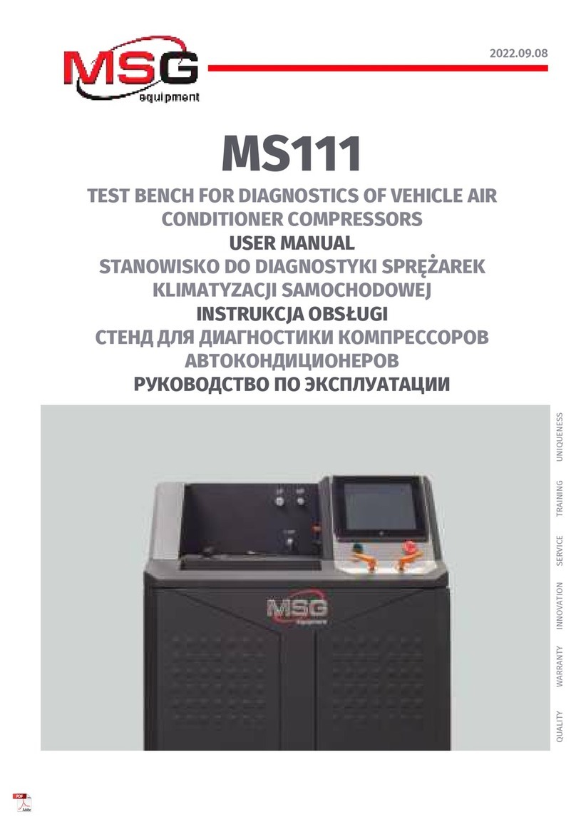
MSG MS111 User manual

MSG MS111
STANOWISKO DO DIAGNOSTYKI SPRĘŻAREK
KLIMATYZACJI SAMOCHODOWEJ
INSTRUKCJA DIAGNOSTYKI SPRĘŻAREK
TEST BENCH FOR COMPRESSORS
OF VEHICLE AIR CONDITIONERS
OPERATION MANUAL “DIAGNOSTICS OF COMPRESSOR”
UNIQUENESS
QUALIT Y SERVICE
WARRANTY TRAINING
INNOVATION
2020.09.16
СТЕНД ДЛЯ ДИАГНОСТИКИ КОМПРЕССОРОВ
КОНДИЦИОНЕРОВ АВТОМОБИЛЯ
ИНСТРУКЦИЯ ПО ДИАГНОСТИКЕ КОМПРЕССОРОВ


Operation manual - test bench MS111
English
INTRODUCTION .................................................................................................................................................. 2
1. TEST BENCH DESCRIPTION............................................................................................................................3
1.1 Main menu.................................................................................................................................................5
1.2 Automatic test menu...............................................................................................................................7
1.3 Manual test menu....................................................................................................................................9
1.4 Test Bench settings menu....................................................................................................................11
1.5 Menu for test results saving and printout .......................................................................................13
2. COMPRESSOR DIAGNOSTICS......................................................................................................................16
2.1 Safety regulations..................................................................................................................................16
2.2 Preparation of a compressor for diagnostics.................................................................................17
2.3 Compressor mounting and dismounting.........................................................................................18
2.4 Diagnostics of a compressor in automatic mode...........................................................................23
3. POST-MAINTENANCE RUN OF A COMPRESSOR.......................................................................................24
4. COMPRESSOR PRE-SALE CHECK................................................................................................................25
5. TEST BENCH MAINTENANCE........................................................................................................................26
CONTENTS
1

The actual Operation Manual contains information about diagnostics of a compressor on Test
Bench MS111.
Test Bench MS111 is intended for diagnostics of piston, axial piston, rotor and scroll compressors
of vehicle climate systems operating on refrigerants R134a and R123yf.
The Test Bench performs the following operations:
•diagnostics of all types of vehicle air conditioner compressors in both automatic and manual
modes;
•diagnostics of AC compressors with V-belt or Poly-V belt drive that use a 12V/24V
electromagnetic clutch and/or a 12V electromagnetic valve;
•check of the electromagnetic clutch and control valve for open circuit, short circuit, and
presence of a diode either in assembly with a compressor or separately from it;
•post-maintenance run of compressors;
•pre-sale testing of new compressors - analogs;
•generation of a test report and its printout.
WARNING! High qualication of the operator is a must when a compressor is tested in
manual mode as improper operation may lead to the unit malfunction. In case you don’t have
enough knowledge or experience in these units testing, it is recommended to use an automatic
mode. Any changes of default settings are unadvisable. Also, you can receive a special training at
the equipment manufacturing facility.
WARNING! MSG Equipment shall not be held responsible for any damage to Test Bench MS111
resulted from its improper operation.
INTRODUCTION
2
Operation manual - test bench MS111
English

1. TEST BENCH DESCRIPTION
3
The Test Bench consists of the following major components (Fig.1): Test Bench housing - 1; power
compartment door - 2; mounting face - 3; control panel - 4; service compartment door - 5; swivel
wheels with a brake - 6.
All diagnostic procedures with the tested unit are performed on the mounting face. The mounting
face contains:
34
Figure 1 – Major components of the Test Bench
2 5
1 6
Operation manual - test bench MS111
English

4
1 – Compressor drive belts: V-belt and Poly-V belt.
2 – Compressor xing chain.
3 – Dust cover. The diagnostic procedure is suspended when the cover is opened.
4 – Compressor temperature sensor. Depended on the model, the bench can be equipped with
either a contact or a contact-free sensor.
5 – Connecting tting for a low-pressure hose.
6 – Connecting tting for a high-pressure hose.
7 – Compressor control valve connection terminals. Adherence to polarity is not necessary.
8 – Compressor electromagnetic clutch connection terminals. Adherence to polarity is not
necessary.
34 5 6
7
8
1
2
Figure 2 – Mounting face of the Test Bench
Operation manual - test bench MS111
English

5
Control panel (Fig.3) includes the following elements:
1 – LP valve: low-pressure hose control.
2 – Start button “OFF/ON”: Test Bench power on/off. Button “OFF/ON” cannot be activated when
button “EMERGENCY STOP” is pressed.
3 – Touch screen: diagnostic data display and control of the Test Bench.
4 – Button “EMERGENCY STOP”: emergency shutdown.
5 – HP valve: control of the high-pressure hose.
1.1 Main menu
Diagnostic procedure is controlled mainly through the touch screen (n.3, Fig.3). Program main
menu (Fig.4) contains:
1 – diagnostic mode selection buttons;
2 – warning messages indicating causes of procedure activation failure;
3 – current pressure indications: discharge side of the compressor - HP1, discharge side of the
Test Bench - HP2, suction side of the compressor – LP;
4 – buttons to pump air and refrigerant from the compressor;
3
2 4
1 5
Figure 3 – Control panel of the Test Bench
Operation manual - test bench MS111
English

6
5 – display of electromagnetic valve and clutch test results;
6 – button to launch diagnostics of electromagnetic clutch or valve;
7 – adjustment of compressor xing chain and drive belt tension: tension/release
76
3
3
2
41
Figure 4 – Main menu of the Test Bench
Operation manual - test bench MS111
English

7
8
765
4
3
2
1
1 – «Vacuum test» - to check the tightness of the compressor and the Test Bench hose joints.
Press the start button – 1 to launch the test (Fig.6). Upon nishing, a message will appear in the
information eld (Fig.6, n.3): “Ok” – positive test result, “Failed” – negative test result.
2 – «Clutch valve test» - to check the electrical characteristics of the compressor clutch coil and
electromagnetic control valve. Press the start button – 1 to launch the test (Fig.7). If the
electromagnetic clutch or valve haven’t been activated or used, the message “Failed” will be
displayed in the appropriate line.
Figure 5. Window of compressor automatic diagnostics
Figure 6. Elements of the tightness test window:
1 – start button; 2 – current cycle time clock;
3 – information eld for test results.
2
3
1
Operation manual - test bench MS111
English
1.2 Automatic diagnostics menu
Program menu “Automatic diagnostics” (Fig.4) contains:

8
Figure 7. Elements of the clutch and/or valve test window:
1 – start button; 2 – information eld for test results;
3 – current through the clutch coil or valve.
Figure 8. Elements of the compressor output window:
1 – start button; 2 – current cycle time clock;
3 – information eld for test results.
Figure 9. Elements of the noise test window:
1 – start button; 2 – button to conrm the abnormal noise;
3 – button to dismiss the abnormal noise; 4 – information eld for test results.
3 – «Productivity test» - to check the compressor output. Press the start button – 1 to launch the
test (Fig 8). The test result will be displayed in the information eld – 3 (Fig.8) as follows: “Ok” –
positive test result, “Failed” – negative test result..
4 – «Noise test» - to detect the abnormal noise coming from the compressor at different speeds.
Press the button -1 to launch the test. During testing it is necessary to conrm or to dismiss the
noise presence (Fig. 9, n. 2 or 3).
5 – Buttons “Start” and “Stop” (Fig.5) – to launch and stop respectively the test procedure run in
automatic mode. Button “Start” launches tests 1-4 (Fig.5) in automatic mode. To perform a proper
diagnostics, follow the indications of the screen. Automatic test can be stopped by pressing
button “Stop” at any moment of time.
1 2 3
2
13
1 2 3 3
Operation manual - test bench MS111
English

6, 7 – A display of measured parameters in the form of gures and graphs:
HP – pressure in the high pressure line, Bar;
LP – pressure in the low pressure line, Bar;
Tepr – evaporator temperature, °С;
Tcom – compressor temperature, °С;
PWM – level of the PWM signal, transmitted to the electromagnetic valve, %;
RPM – motor drive rotation speed (RPMs).
8 – «Results» – button to enter the menu for test results review and save
1.3 Manual test menu
Figure 10 – Manual test menu of the Test Bench
1
2
3
4
5
Program menu «Manual mode» (Fig.10) contains:
9
Operation manual - test bench MS111
English

1 – «НР fan» has two adjustable pressure parameters - Max/Min: the bench maintains pressure
(Bar) in the HP line by controlling the fan speeds.
2 – «LP fan» - setting the evaporator fan speed. By changing the LP fan speed, we change the heat
load on the tested compressor. It simulates the evaporator blow in the car cabin.
3 – «RPM» – selection of the compressor drive speed and direction of rotation. Includes the
following buttons:
•«Left», «Right» – a button to select the rotation direction of the Test Bench drive;
•«Stop» – a button to stop the compressor drive;
•«800», «1500», «3000» – a button to set the drive speed (RPMs);
•«-» and «+» – a button to change the compressor drive speed: one press of the button changes
the speed by one step. The indicator of the actual motor speed (RPMs) is located between the
buttons.
4 – «Electromagnetic clutch and valve control» (Fig.11) includes two buttons for switching on/off
the electromagnetic valve and clutch respectively. When the clutch/valve is activated (by a single
press of the button), the following information is displayed: the consumed current (n.3), diode
presence/absence (n.4), status of the electromagnetic clutch/valve (n.5) where: “OFF” – not
connected, “CB” – circuit break, “SC” – short circuit, “ON” – connected, faultless. Buttons «+»/«-»
(n.6) control the PWM signal transmitted to the electromagnetic valve. Setting the PWM signal
below 30 is not recommended. Productivity of compressors with electromagnetic valves directly
depends on the PWM signal.
“1.9” and “2.9” (n.8) are LP values (Bar) at which the electromagnetic clutch switches on/off.
10
Operation manual - test bench MS111
English

11
5 – «Results» – a button to enter the menu for save and review test results obtained in manual
mode.
Settings menu consists of two tabs: “Main settings” (Fig.12) and “Sensor settings” (Fig.13).
Menu “Main settings” includes the following:
1 – Adjustment of the belt and chain tension.
2 – Setting of the evaporator fan speeds in manual test mode. The speeds are set in “LP fan” menu
(n.2, Fig.10) in percentage terms (from 0 to 100%).
3 – Setting the voltage drop at the refrigerant lter at which message “Replace lter” will be
displayed. The recommended values are within the range from 0.5 to 0.7. Setting values lower
than the recommended ones will result in frequent replacement of the lters well before their
service life is fully exhausted. Higher values will cause an increased load on the tested
compressor and the Test Bench components.
4 – Selection of the program interface language.
5 – Selection of the logo for the test report. In case you need to change the logo, press on the eld
with the logo - 5.
6 – Prompt messages setting.
7 – Selection of pressure units.
Button “Open” allows the MS111 program to use the factory calibration values for pressure
sensors.
1.4 Test Bench settings menu
Figure 11. Elements of the clutch and valve control window:
1 – button to switch the clutch on/off; 2 – button to switch the valve on/off; 3 – valve
consumption current; 4 – diode presence/absence indicator; 5 – status of the valve;
6 – buttons to change the level of the PWM signal; 7 – status of the clutch (similar to n. 3, 4, 5);
8 – LP values for switching the clutch on/off.
2
3 4
6
7
8
5
1
Operation manual - test bench MS111
English

Menu «Sensor settings» (Fig.14) includes the following:
1 – Sensors calibration. Any change of these settings is prohibited as it may cause the Test Bench
breakdown. These settings are intended for specialists of MSG Equipment technical service for
the purpose of maintenance and repair.
2 – Setting vacuum for refrigerant pumping after the compressor diagnostics has been
completed. The recommended value is -0.6 Bar. The higher value will raise up the risk of the air
ingress into the system and subsequent deterioration of the Test Bench performance. The lower
value is permitted. It will cut the time necessary for the refrigerant evacuation albeit increase its
loss.
3 – Setting vacuum for air pumping before launching the compressor diagnostics. The
recommended value is -0.9 Bar. The higher value is not recommended as the Test Bench may not
reach it. The lower value is permitted. It will cut the time of vacuuming, but will increase the
amount of air in the system and therefore the frequency of the Test Bench relling.
4 – Setting additional pumping time after the set vacuum has been achieved. Regardless of the
pressure, the Test Bench will be pumping the unit during the pre-set time period to allow
evacuation of the refrigerant separated from oil. We do not recommend to set additional
pumping time more than 5 minutes - 90% of the refrigerant will be released from the oil within
the rst minute.
12
Figure 12 – Screen for main settings of the Test Bench
1
6
5 4
3
7
2
Operation manual - test bench MS111
English

13
5 – Setting the timer clock for emergency stop. The process will be stopped at the pre-set time
regardless of the pre-set vacuum value.
Figure 13 – Sensors Setup window
1.5 Menu for test results save and review
1
5
3
4
2
Upon nishing the diagnostics, press “Results” (n.8, Fig. 5 or n.5, Fig.10) to review, save or print
the test results. The form of the diagnostic report is individual for each test mode (Fig.14, 15).
Operation manual - test bench MS111
English

Operation manual - test bench MS111
English
14
To save the results, press “Save” in the window for test results (Fig.14, 15). Fill in all the elds in
the appeared window and press “Save”. To delete the information in the elds, touch “Reset”. To
change the input language, press sequentially “Shift”, “Alt”, “Shift” on the touch keyboard.
6.1 Cleaning and Care
Figure 14 – Window for automatic test results
Рисунок 15 – Window for manual test results

15
Figure 16 – Window for test results saving
Press “Open” to review the previously saved test results (Fig. 14, 15). The list of saved results will
be displayed in the appeared window. In the rst column there is an indication of the test mode
- “Auto” or “Manual”.
Select the required test result by pressing the appropriate line once. Then press “Open” to view
the result. Press “Back” to return.
WARNING! Test results obtained in automatic and manual modes can be viewed in their
appropriate windows only. The window in Fig.14 is for automatic mode test results, the window
in Fig.15 – for test results obtained in manual mode.
Operation manual - test bench MS111
English

16
Figure 17 – Window for selection of saved test results
2. COMPRESSOR DIAGNOSTICS
2.1 Safety regulations
1. The Test Bench should only be used by the persons qualied to operate the test benches of
certain types who received a special training in equipment safety operation.
2. Before the unit dismounting from the test bench, the refrigerant should be evacuated.
3. Press button "ON/OFF" either in case of power failure or emergency, or before the equipment
cleaning and servicing to switch the Test Bench off.
4. The workplace should be clean, well-lit and spacious.
5. The use of the faulty or unearthed Test Bench is strictly prohibited.
6. The compressor mounting and/or dismounting should be conducted carefully to prevent its
fall.
7. The unit with the running drive may not be left on the test bench unattended.
8. It is strictly forbidden to open the door of the power compartment when the test bench is
connected to 400V power supply.
Operation manual - test bench MS111
English

17
9. Avoid any body contact with the refrigerant, it may lead to a frostbite (R134a boiling point is
-26°С, R1234yf boiling point is -30°С).
10. It is strongly recommended to use protective gloves and glasses.
11. Any refrigerant is a colorless and odorless gas which is heavier than air. Entering the
atmosphere, it can cause asphyxiation or heart rhythm disorders. That is why, the Test Bench
should be used in well-ventilated premises only. Available exhaust units in the room must be
switched on.
12. Refrigerant R-1234yf is a highly ammable gas. Take extra care when working with this
refrigerant.
13. Open ame sources are allowed nowhere near the test bench operating area. Smoking near
the Test Bench is prohibited. A regular re-extinguishing appliance is a must.
14. If protective caps of the lling ttings cannot be easily unscrewed, there is a risk of injury due
to the valves poor tightness.
2.2 Preparation of a compressor for diagnostics
Prepare the compressor for diagnostics as follows:
1.Clean the compressor surface from dirt with a compressed air stream.
2.Unscrew the oil lling cap. Drain the oil into a clear container.
Figure 18. Monitoring of compressor oil condition
Operation manual - test bench MS111
English

18
3. Check the oil condition. Wear debris, dark or black color of the oil signal that major moving
components of the compressor are signicantly worn out. We do not recommend testing such a
compressor on the bench as testing of the known-faulty compressor may lead to the
contamination of the bench hydraulic system.
4. If the condition of oil is good, add 20-30 ml of the test oil (PAG46yf) into the compressor and
screw the cap in.
5. Find proper ttings in the equipment set and x them on the compressor. Now the compressor
is ready for use.
2.3 Compressor installation and connection
1. Switch the bench on by pressing button “OFF/ON”. Wait for the rmware to load.
2. Install the compressor on the mounting face.
3. Run the chain around the compressor and into the chain xer. Press “Tension chain” to x
the unit (Fig.4, n.7). The tensioning will stop automatically.
WARNING! Align the pulley in parallel with the belt before xing the compressor.
WARNING! Be careful when tensioning the chain to avoid the risk of injury.
Figure 19. Correct position of the compressor belt and pulley
Operation manual - test bench MS111
English
Other manuals for MS111
2
Table of contents
Languages:
Other MSG Test Equipment manuals
Popular Test Equipment manuals by other brands

Teledyne Lecroy
Teledyne Lecroy WaveSurfer 10 Operator's manual

BRUEL & KJAER
BRUEL & KJAER 4226 user manual

Bosch
Bosch OBD1100 user guide

Psiber Data Systems
Psiber Data Systems Psiber PINGER user guide

HALE
HALE SmartFOAM 1.7AHP FOAM CALIBRATION QUICKSTART

BTE Technologies
BTE Technologies Multi-Cervical Unit user manual