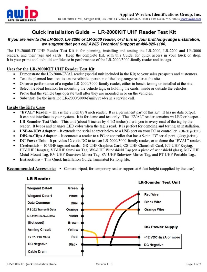
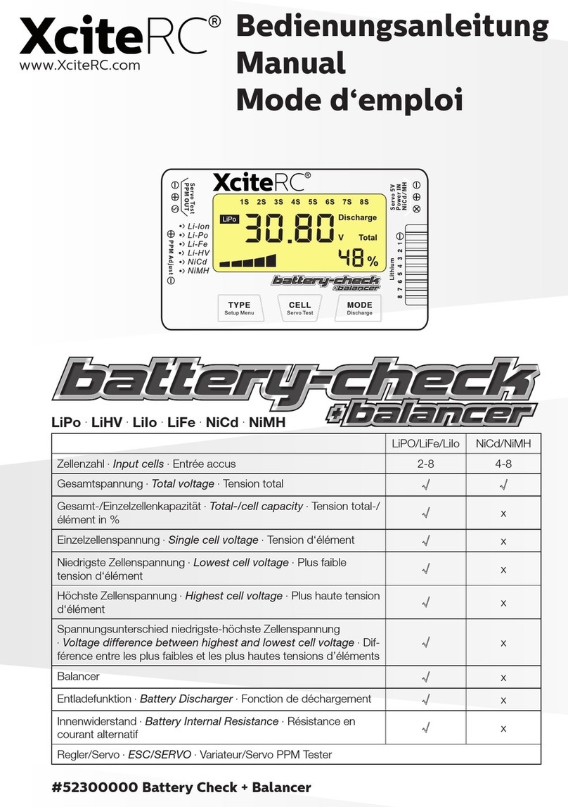
BEAMEX MC5 Guide

For Main Firmware Version 1.90
Calibrating and Adjusting MC5 / 011912
Calibration and
Adjustment Instructions
for MC5 Multifunction Calibrator
Enable Adjustment Mode
Select Quantity and Function/Port
Calibrate (Compare against a
more accurate instrument)
Adjustment required?
Store adjustment data
Enter reference values to
adjust a Quantity in the calibrator
More Quantities to calibrate?
Did one or
more Quantities in
all modules require
adjustment?
Enter the calibration date and
Calibration Laboratory data in
the Module Settings window
yes
no
no
yes
no
yes
Start
End
More Quantities to adjust?
no
yes

Calibration and Adjustment Instructions for MC5 Multifunction Calibrator For Main Firmware Version 1.90
Page 2/16
Contents
General.......................................................................................................... 3
Equipment Required for Performing the Calibration............................................................3
Recommended Calibration Points.......................................................................................4
E module......................................................................................................................................4
ET module ...................................................................................................................................4
Pressure modules........................................................................................................................4
Calibrating and Adjusting the Calibrator ................................................... 5
Enabling and Starting the Adjustment Mode.......................................................................5
Calibration ...........................................................................................................................5
Adjustment of Measurement Ranges..................................................................................6
Adjusting the Voltage Measurement in E Module (±50 V)...........................................................6
Adjusting the Low Voltage Measurement in E Module (±1 V)......................................................6
Adjusting the Current Measurement in E Module (±100 mA) ......................................................7
Adjusting the Frequency Measurement in E Module (±0.0027 … 50000 Hz)..............................7
Adjusting the Resistance Measurement in ET Module (0 … 4000 ohm).....................................8
Adjusting the Low Voltage Measurement in ET Module (±500 mV).............................................8
Adjusting the Pressure Measurement of a Pressure Module.......................................................9
Adjusting the Temperature Measurement of the Internal Reference Junction Module..............10
Adjustment of Generation/Simulation Ranges ..................................................................11
Adjusting the Current Generation in E Module (0 … 25 mA).....................................................11
Adjusting the Resistance Simulation in ET Module (0 … 4000 ohm) ........................................12
Adjusting the Low Voltage Generation in ET Module (±500 mV)...............................................13
Adjusting the Frequency Generation in ET Module (2.7 mHz … 50 kHz)..................................13
Adjusting the Voltage Generation in ET Module (±12 V)...........................................................14
Adjusting the Current Generation in ET Module (±25 mA) ........................................................15
Saving Adjustment Data....................................................................................................16
Setting the Calibration Date When No Adjustment Was Required ...................................16
Ending Adjustment Mode ..................................................................................................16

Calibration and Adjustment Instructions for MC5 Multifunction Calibrator For Main Firmware Version 1.90
Page 3/16
General
The tolerances, linearity errors and temperature factors of the components used in the Beamex
Calibrators have been carefully considered during the specification tests at the factory. All nec-
essary parameters have been saved into the EEPROM memory of each measurement module.
It is not necessary to renew the calibration if certain components in the analogy part of the cali-
brator are not replaced. Anyhow, some characteristics can deviate from the original values dur-
ing the time. The periodical calibration is thus necessary in order to maintain the full accuracy of
the calibrator. In the beginning of the calibrator’s life span, the recommended calibration period
is one year. When the calibration history has been established, the calibration period can be
extended.
The whole calibration procedure can be made without opening the calibrator. The calibration
procedure is made as easy as possible. The calibration requires, however, some very accurate
instruments. If You do not have all the necessary calibration instruments, send the device to
Beamex’s accredited calibration laboratory for calibration.
Equipment Required for Performing the Calibration
For the complete calibration you need the following equipment:
1) DC calibrator, capable of generating the
- currents, voltages and low voltages measured with the E module.
- low voltages measured with the ET module.
2) DC meter(s), capable of measuring the
- currents generated with the E module
- currents, voltages and low voltages generated with the ET module
- generated voltages in the calibration of the ET module's resistance simulation.
3) Frequency generator capable of generating the frequencies measured with the E module.
4) Frequency measurement meter, capable of measuring the frequencies generated with the
ET module.
5) Precision resistors, for calibrating the ET modules resistance measurement.
6) A good quality thermocouple of type E, J, K or T. The sensor wires should be continuous
without extension or plug. The error of the sensor output at the condition where the sensor is
in the used temperature reference and the reference junction in 20 to 30°C should be known
and taken into account in the calibration.
7) An ice bath or another known temperature reference. The combined uncertainty of the tem-
perature reference and the thermocouple together should be less than 0.05°C.
8) A dead weight tester with the accuracy of 0,02 % RDG or better for the generation of the
necessary testing pressures. Required for the different pressure modules used with the cali-
brator.
You can replace items 6 and 7 with a small size temperature sensor and measuring device with
calibrated accuracy better than 0.05°C. The sensor must be small enough to fit inside the RJ
module. It should not noticeably conduct heat to or from the environment.
The accuracy of the necessary equipment should be about three times better than the accuracy
specified for the calibrator (see the calibrator’s Technical Data Sheet). If the accuracy of the
calibration equipment are worse, the calibration period should be shorter.

Calibration and Adjustment Instructions for MC5 Multifunction Calibrator For Main Firmware Version 1.90
Page 4/16
Recommended Calibration Points
The calibration points presented here are mostly the same as on the Calibration Certificate de-
livered with the calibrator. As the heading indicates, these are recommendations, not the only
suitable calibration points.
E module
Low Voltage
meas., V
(±1 V)
Voltage
meas., V
(±50 V)
Current
meas., mA
(±100 mA)
Current
generation, mA
(0 … 25 mA)
Frequency meas-
urement, Hz
(0.0027…50000 Hz)
-1.00000 -50.000 -100.000 0.000 1
0.00000 0.000 0.000 5.000 10
0.25000 10.000 4.000 10.000 100
0.50000 20.000 12.000 15.000 1000
0.75000 30.000 20.000 20.000 10000
1.00000 40.000 50.000 25.000 50000
50.000 100.000
ET module
Low Voltage
meas. & gen., mV
(±500 mV)
Voltage
gen., V
(±12 V)
Current gen.,
mA
(±25 mA)
Frequency genera-
tion, Hz
(2.7 mHz…50 kHz)
Resistance
meas., ohm
(0 … 4000 ohm)
Resistance
simul., ohm
(0 … 4000 ohm)
-500.00 -12.000 0.000 15.000 5.000
0.00 0.000 5.000 10 80.000 130.00
10.00 2.500 10.000 100 160.00 145.00
50.00 5.000 15.000 1000 320.00 270.00
250.00 7.500 20.000 10000 1000.00 290.00
500.00 10.000 25.000 50000 2000.00 540.00
12.000 4000.00 570.00
1050.00
1200.00
2100.00
2300.00
4000.00
Pressure modules
Barometric
module, kPa abs
(80…120 kPa)
Gauge
modules,
(0 … X kPa)
Combined modules with a
symmetrical range
(±X kPa)
Combined modules with
an asymmetrical range
(-100 … X kPa)
80.00 0 % of span 0 % of span 0 % of span
90.00 20 % of span 20 % of span 20 % of span
100.00 40 % of span 40 % of span 40 % of span
110.00 60 % of span 60 % of span 60 % of span
120.00 80 % of span 80 % of span 80 % of span
100 % of span 100 % of span 100 % of span
80 % of span 80 % of span 80 % of span
60 % of span 60 % of span 60 % of span
40 % of span 40 % of span 40 % of span
20 % of span 20 % of span 20 % of span
0 % of span 0 % of span 0 % of span
-20 % of span -20 kPa
- 40 % of span -40 kPa
- 60 % of span -60 kPa
- 80 % of span -80 kPa
- 100 % of span -99 kPa
Note. The exact values of the calibration
points may vary depending on the dead weight tester in use.

Calibration and Adjustment Instructions for MC5 Multifunction Calibrator For Main Firmware Version 1.90
Page 5/16
Calibrating and Adjusting the Calibrator
Calibration
Since adjusting the measurement ranges affect the generation ranges (via feedback measure-
ment), all Quantity and Function/Port settings should first be calibrated before making any
adjustments. Do the calibration in Basic Mode and use the recommended calibration points pre-
sented on page 4or any other suitable set of calibration points.
When all calibrations are done, prepare for enabling the adjustment mode by shutting down the
calibrator. To save the calibration date, you need to enable the adjustment mode even if no ad-
justment is required. For further information, see next chapter.
Enabling the Adjustment Mode
By default, the calibrator does not support adjustment of its
own measurement generation and simulation signals. This
prevents the calibrator from being accidentally adjusted.
To enable the Adjustment Mode, do as follows:
1. Start the calibrator. When the screen with the mod-
ule version numbers etc. appear, press the D/Wait
function key
Note.
Pressing the D/Wait function key is not needed if the calibrator's
calibration due date has expired. Then the calibrator beeps and
stops automatically on this screen and displays the message
"Calibrate soon".
Adjustment mode enabled
Wait
Serial number
E module version
Calibration due date
Main version
ET module version
23512365
1.50
20.03.2003
1.90
1.70
www.beamex.com
2. Press the key.
Check that the text "Adjustment Mode enabled" appears on the status bar.
Enabling the Adjustment Mode makes the Adjustment menus available.
To start adjusting the calibrator, select:
D/Menu, C/Others, 2/Maintenance, 2/Calibrator Adjustment and
1/Start Adjustments.
Notes:
The commands apply when the calibrator is in Basic State.
The measurement window of a Quantity is enlarged to indicate that calibration/adjustment is in progress.
If there is need for adjustment see chapters Adjustment of Measurement Ranges and
Adjustment of Generation/Simulation Ranges on pages 6and 11 respectively.
If no adjustment is needed, set the calibration date into the calibrator’s memory. To do that, see
chapter Setting the Calibration Date When No Adjustment Was Required on page 16.

Calibration and Adjustment Instructions for MC5 Multifunction Calibrator For Main Firmware Version 1.90
Page 6/16
Adjustment of Measurement Ranges
Adjusting the Voltage Measurement in E Module (±50 V)
Quantity: Voltage
Function/Port: E: Voltage Measurement
Use an accurate voltage source and connect it to the
calibrator’s terminals highlighted in the adjacent picture.
In case the accuracy of the voltage source is not good
enough, check the correct voltage using an accurate
Digital Multimeter.
Adjustment point ranges, mV
1: 9 … 12
2: 19 … 25
3: 39 … 50
Generate a voltage that is inside the limits of the first
adjustment point range. Enter the correct voltage seen
on the Digital Multimeter’s display to Span Reference
Value field in the calibrator. Continue through all the ad-
justment points
When all adjustment points are checked, select either
another Quantity and Function/Port combination or save
the adjustment result as described in chapter Saving
Adjustment Data on page 16.
Source/DMM V
10.00021
17.10.2002 10:21
Voltage
E: Voltage Measurement
V10.0001
Span Reference Value 10.00021
MENU
Calibration
Mode
MULTIFUNCTION CALIBRATOR
T/C, Low V 4-w meas
R, RTD
3 & 4-w meas
V, I,+24V Imeas/sink
Low V
HART®
T/C INT. RJ
T/C OR EXT
WIRES ONLY
2-w xmtr
V, ,
?
MEASURE
OUTPUTSENSOR MEASURE & SIMULATE
ET E
Max input:
60 VDC/30VAC
Adjusting the Low Voltage Measurement in E Module (±1 V)
Quantity: Voltage
Function/Port: E: Low Voltage Measurement
Use an accurate millivolt source and connect it to the
calibrator’s terminals highlighted in the adjacent picture.
In case the accuracy of the voltage source is not good
enough, check the correct voltage using an accurate
Digital Multimeter.
Adjustment point ranges, mV
1: 200 … 250
2: 400 … 500
3: 800 … 1000
Generate a voltage that is inside the limits of the first
adjustment point range. Enter the correct voltage seen
on the Digital Multimeter’s display to Span Reference
Value field in the calibrator. Continue through all the ad-
justment points
When all adjustment points are checked, select either
another Quantity and Function/Port combination or save
the adjustment result as described in chapter Saving
Adjustment Data on page 16.
Source/DMM mV
220.000 12
17.10.2002 9:25
Voltage
E: Low Voltage Meas.
mV219.999
Span Reference Value 220.00012
MENU
Calibration
Mode
MULTIFUNCTION CALIBRATOR
T/C, Low V 4-w meas
R, RTD
3 & 4-w meas
V, I,+24V Imeas/sink
Low V
HART®
T/C INT. RJ
T/C OR EXT
WIRES ONLY
2-w xmtr
V, ,
?
MEASURE
OUTPUTSENSOR MEASURE & SIMULATE
ET E
Max input:
60 VDC/30VAC

Calibration and Adjustment Instructions for MC5 Multifunction Calibrator For Main Firmware Version 1.90
Page 7/16
Adjusting the Current Measurement in E Module (±100 mA)
Quantity: Current
Function/Port: E: Current Measurement
Use an accurate current source and connect to the cali-
brator’s terminals highlighted in the adjacent picture. In
case the accuracy of the current source is not good
enough, check the correct current using an accurate
Digital Multimeter.
Adjustment point ranges, mA
1: 20 … 50
2: 80 …100
Generate a current that is inside the limits of the first
adjustment point range. Enter the correct current seen
on the Digital Multimeter’s display to Span Reference
Value field in the calibrator. Continue through all the ad-
justment points
When all adjustment points are checked, select either
another Quantity and Function/Port combination or save
the adjustment result as described in chapter Saving
Adjustment Data on page 16.
Source/DMM mA
24.996 72
17.10.2002 9:27
Current
E: Current Measurement
mA24.9997
Span Reference Value 24.99672
MENU
Calibration
Mode
MULTIFUNCTION CALIBRATOR
T/C, Low V 4-w meas
R, RTD
3 & 4-w meas
V, I,+24V Imeas/sink
Low V
HART®
T/C INT. RJ
T/C OR EXT
WIRES ONLY
2-w xmtr
V, ,
?
MEASURE
OUTPUTSENSOR MEASURE & SIMULATE
ET E
Max input:
60 VDC/30VAC
Adjusting the Frequency Measurement in E Module (±0.0027 … 50000 Hz)
Quantity: Frequency
Function/Port: E: Frequency Meas.
Use an accurate frequency source and connect to the
calibrator’s terminals highlighted in the adjacent picture.
In case the accuracy of the frequency source is not good
enough, check the correct frequency using an accurate
Digital Multimeter.
Adjustment point range, Hz
800 … 50000
Generate a frequency that is inside the limits of the ad-
justment point range. Enter the correct frequency seen
on the Digital Multimeter’s display to Span Reference
Value field in the calibrator.
Select either another Quantity and Function/Port combi-
nation or save the adjustment result as described in
chapter Saving Adjustment Data on page 16.
Source/DMM kHz
10.000 00
17.10.2002 10:30
Frequency
E: Frequency Meas.
Hz1000.00
Trigger Level [V]
Span Reference Value 1000.00000
Field MENU
Calibration
Mode
2.00
MULTIFUNCTION CALIBRATOR
T/C, Low V 4-w meas
R, RTD
3 & 4-w meas
V, I,+24V Imeas/sink
Low V
HART®
T/C INT. RJ
T/C OR EXT
WIRES ONLY
2-w xmtr
V, ,
?
MEASURE
OUTPUTSENSOR MEASURE & SIMULATE
ET E
Max input:
60 VDC/30VAC
Note.
The default trigger level is 2 V. Change it to a more suitable level, if needed.

Calibration and Adjustment Instructions for MC5 Multifunction Calibrator For Main Firmware Version 1.90
Page 8/16
Adjusting the Resistance Measurement in ET Module (0 … 4000 ohm)
Quantity: Resistance
Function/Port: ET: Resistance Meas.
Use precision resistors and connect them to the cali-
brator’s terminals highlighted in the adjacent picture. In
case the accuracy of the resistors are not good enough,
check the correct resistance using an accurate Digital
Multimeter. Also read the note below the picture.
Adjustment point ranges, ohm
1: 60 … 87
2: 120 … 175
3: 240 … 350
4: 700 … 1025
5: 1400 … 2050
6: 2800 … 4100
Select a precision resistor that is inside the limits of the
first adjustment point range. Enter the correct resistance
seen on the Digital Multimeter’s display to Span Refer-
ence Value field in the calibrator. Continue through all
the adjustment points
When all adjustment points are checked, select either
another Quantity and Function/Port combination or save
the adjustment result as described in chapter Saving
Adjustment Data on page 16.
MENU
Calibration
Mode
Precision Resistor
W
70.0000
17.10.2002 10:26
Resistace
ET: Resistance Meas.
W69.998
Span Reference Value 70.00012
MULTIFUNCTION CALIBRATOR
T/C, Low V 4-w meas
R, RTD
3 & 4-w meas
V, I,+24V Imeas/sink
Low V
HART®
T/C INT. RJ
T/C OR EXT
WIRES ONLY
2-w xmtr
V, ,
?
MEASURE
OUTPUTSENSOR MEASURE & SIMULATE
ET E
Max input:
60 VDC/30VAC
Note.
Do not connect both the calibrator and the
Digital Multimeter to the resistor simultane-
ously. The resistance measurement currents
of the calibrator and the Digital Multimeter
disturb each other resulting in unreliable
measurements.
Adjusting the Low Voltage Measurement in ET Module (±500 mV)
Quantity: Voltage
Function/Port: ET: Low V. Sensor Mea
Use an accurate millivolt source and connect to the cali-
brator’s terminals highlighted in the adjacent picture. In
case the accuracy of the millivolt source is not good
enough, check the correct voltage using an accurate
Digital Multimeter.
Adjustment point ranges, mV
1: 90 … 125
2: 150 … 250
3: 400 … 500
Generate a voltage that is inside the limits of the first
adjustment point range. Enter the correct voltage seen
on the Digital Multimeter’s display to Span Reference
Value field in the calibrator. Continue through all the ad-
justment points
When all adjustment points are checked, select either
another Quantity and Function/Port combination or save
the adjustment result as described in chapter Saving
Adjustment Data on page 16.
Source/DMM mV
499.97357
17.10.2002 9:42
Voltage
ET: Low V. Sensor Meas.
mV499.97
Span Reference Value 499.97357
Field MENU
Calibration
Mode
MULTIFUNCTION CALIBRATOR
T/C, Low V 4-w meas
R, RTD
3 & 4-w meas
V, I,+24V Imeas/sink
Low V
HART®
T/C INT. RJ
T/C OR EXT
WIRES ONLY
2-w xmtr
V, ,
?
MEASUREOUTPUTSENSOR MEASURE & SIMULATE
ET E
Max input:
60 VDC/30VAC

Calibration and Adjustment Instructions for MC5 Multifunction Calibrator For Main Firmware Version 1.90
Page 9/16
Adjusting the Pressure Measurement of a Pressure Module
(Measurement Range Varies Depending on the Pressure Module)
Quantity: Pressure
Function/Port: P1…, P2…, P3…, PB…, EXT…
(depending on the selected/available modules)
Use a dead weight tester and connect it to the pressure
module to be adjusted.
Adjustment Points
The span adjustment point range for all gauge pressure
modules is 60 … 100 % of span. The zero adjustment
point is zero.
Ensure that the input connector of the gauge pressure
module is not connected to anything. Move the field
pointer to Zero Reference Value field in the calibrator
and enter the zero point value.
Connect the dead weight tester and generate a pressure
near the maximum span value. Move the field pointer to
Span Reference Value field in the calibrator and enter
the span value.
When ready, select either another Quantity and Func-
tion/Port combination or save the adjustment result as
described in chapter Saving Adjustment Data on page
16.
Field MENU
Calibration
Mode
17.10.2002 10:40
Pressure
P2: INT20C/-100 ... 2068 kPa g
gauge
kPa1800.22
Zero Reference Value
Span Reference Value 0.00000
???????
Dead Weight Tester
kPa
1800.0820
T/C, Low V 4-w meas
R, RTD
3 & 4-w meas
V,
I,+24V Imeas/sink
Low V
HART®
T/C INT. RJ
T/C OR EXT
WIRES ONLY
2-w xmtr
V, ,
?
MEASUREOUTPUTSENSOR MEASURE & SIMULATE ET E
Max input:
60 VDC/30 VAC
MULTIFUNCTION CALIBRATOR
Adjustment Points for a Barometric Module
The barometric module's zero correction point range is 800 … 1200 mbar (11.6 … 17.4 psi). The
span correction point range is the same but there should be at least 200 mbar abs (approx.
2.9 psi abs) difference between the used zero adjustment and the used span adjustment point.
The connector for the Barometric Module is on the back side of the calibrator. The thread is M5.
Note.
Usually a one point trim is enough for adjusting the barometric module. This is done by comparing the atmospheric
pressure readout of the calibrator’s barometric module to the readout of a more accurate barometric pressure indicator.
When the correct barometric pressure is entered, the calibrator actually adjusts the zero point so that the readout for
the current atmospheric pressure is the same as the entered value.

Calibration and Adjustment Instructions for MC5 Multifunction Calibrator For Main Firmware Version 1.90
Page 10/16
Adjusting the Temperature Measurement of the
Internal Reference Junction Module
For obtaining best results when adjusting the Internal
Reference Junction Module, do the adjustment after the
calibrator has been shut down and not connected to a
charger overnight. Then the temperature inside the cali-
brator is stabilized to the same temperature as the envi-
ronment.
Quantity: T/C Temperature
Function/Port: ET: TCi(mea)
Connect an accurate thermocouple to the INT. RJ termi-
nals. Use an ice bath and place the thermocouple into
the bath.
Adjustment Point
Only the zero adjustment point need to be checked.
Enter the correct bath temperature to the Zero Refer-
ence Value field in the calibrator.
When ready, select either another Quantity and Func-
tion/Port combination or save the adjustment result as
described in chapter Saving Adjustment Data on page
16.
Temp. Bath °C
0.00
Field MENU
Calibration
Mode
07.11.2002 14:54
T/C-temperature
ET: T/C-Meas., Int RJ K NiCr/NiAl
°C (ITS90)0.02
Zero Reference Value
Span Reference Value 0.00
???????
RJ: Internal 23.02
MULTIFUNCTION CALIBRATOR
T/C, Low V 4-w meas
R, RTD
3 & 4-w meas
V, I,+24V Imeas/sink
Low V
HART®
T/C INT. RJ
T/C OR EXT
WIRES ONLY
2-w xmtr
V, ,
?
MEASURE
OUTPUTSENSOR MEASURE & SIMULATE
ET E
Max input:
60 VDC/30VAC

Calibration and Adjustment Instructions for MC5 Multifunction Calibrator For Main Firmware Version 1.90
Page 11/16
Adjustment of Generation/Simulation Ranges
The accuracy of a generation range depends on the accuracy of the respective measurement
range. Therefore the measurement range should be adjusted before trimming the generation
range. Trimming the generation range affects the overshoot and damping of the generated
value.
Several of the calibrators generation range adjustment windows include the feedback measure-
ment value. This can be used for trimming the generation range. Using an external Digital Mul-
timeter is optional for these measurement ranges.
Adjusting the Current Generation in E Module (0 … 25 mA)
Quantity: Current
Function/Port: E: Current Source/Sink
Power supply needed for the current generation can be
provided either from the calibrator or from an external
power supply unit. The connection depends on the used
power supply.
The lowermost measurement value in the current gen-
eration window is the calibrator’s own feedback meas-
urement of the generated current. It is accurate enough
for trimming the generated value. The Digital Multimeter
connected to the loop is optional.
Power Supplied from the Calibrator
The uppermost picture defines the connection when the
calibrator provides the power supply.
External Power Supply
The lowermost picture defines the connection when an
external device is used for power supply.
Adjustment Procedure
The adjustment procedure is the same for both connec-
tions.
Adjustment point ranges, mA
Low: 0.5 …5
High: 20 …25
Move the field indicator to the uppermost field and enter
a current generation value that is inside the limits of the
low adjustment point range. Enter the correct current
seen on the Digital Multimeter’s display to Span Refer-
ence Value field in the calibrator. Then generate a cur-
rent that is inside the high adjustment point range and
enter the correct value for that point too. Repeat the low
and high adjustments until the current generation is ac-
curate enough.
When ready, select either another Quantity and Func-
tion/Port combination or save the adjustment result as
described in chapter Saving Adjustment Data on page
16.
DMM mA
24.997 60
Field MENU
Calibration
Mode
17.10.2002 9:35
Current
E: Current Source/Sink
mA25.0000
Measurement mA
Span Reference Value 24.996
25.996
MULTIFUNCTION CALIBRATOR
T/C, Low V 4-w meas
R, RTD
3 & 4-w meas
V, I,+24V Imeas/sink
Low V
HART®
T/C INT. RJ
T/C OR EXT
WIRES ONLY
2-w xmtr
V, ,
?
MEASURE
OUTPUTSENSOR MEASURE & SIMULATE
ET E
Max input:
60 VDC/30VAC
Supply
DMM
V
mA
24.0
24.997 60
Field MENU
Calibration
Mode
17.10.2002 9:35
Current
E: Current Source/Sink
mA25.0000
Measurement mA
Span Reference Value 24.998
24.998
MENU
MULTIFUNCTION CALIBRATOR
T/C, Low V 4-w meas
R, RTD
3 & 4-w meas
V, I,+24V Imeas/sink
Low V
HART®
T/C INT. RJ
T/C OR EXT
WIRES ONLY
2-w xmtr
V, ,
?
MEASUREOUTPUTSENSOR MEASURE & SIMULATE
ET E
Max input:
60 VDC/30VAC

Calibration and Adjustment Instructions for MC5 Multifunction Calibrator For Main Firmware Version 1.90
Page 12/16
Adjusting the Resistance Simulation in ET Module (0 … 4000 ohm)
Quantity: Resistance
Function/Port: ET: Resistance Sim.
Connect an accurate Digital Multimeter to the calibra-
tor’s terminals highlighted in the adjacent picture.
The resistance simulation range is divided into
subranges that are adjusted as separate high and low
point pairs.
Adjustment points, ohm
Low 1: 1
High 1: 100
Low 2: 160
High 2: 250
Low 3: 300
High 3: 500
Low 4: 600
High 4: 1000
Low 5: 1200
High 5: 2000
Low 6: 2400
High 6: 4000
DMM W
70.00103
17.10.2002 10:27
Resistance
ET: Resistance Sim.
W70.00
Span Reference Value 70.00103
Field MENU
Calibration
Mode
MULTIFUNCTION CALIBRATOR
T/C, Low V 4-w meas
R, RTD
3 & 4-w meas
V, I,+24V Imeas/sink
Low V
HART®
T/C INT. RJ
T/C OR EXT
WIRES ONLY
2-w xmtr
V, ,
?
MEASUREOUTPUTSENSOR MEASURE & SIMULATE
ET E
Max input:
60 VDC/30VAC
Move the field indicator to the uppermost field and enter the Low 1 adjustment point value. Then
enter the correct resistance seen on the Digital Multimeter’s display to Span Reference Value
field in the calibrator. Go back to the uppermost field and enter the High 1 adjustment point
value. Then enter the correct resistance seen on the Digital Multimeter’s display to Span Refer-
ence Value field in the calibrator. Repeat Low 1 and High 1 points if necessary.
When a subrange is adjusted, continue with the next one until all subranges are adjusted.
When ready, select either another Quantity and Function/Port combination or save the adjust-
ment result as described in chapter Saving Adjustment Data on page 16.
Note.
Resistance simulation is valid with measurement current
0.2 ... 2 mA (1 ... 250 ohm), 0.05 <Imeas•Rsim < 0.5 V (250 … 4000 ohm).
Ohm/RTD simulation settling time 1 ms.

Calibration and Adjustment Instructions for MC5 Multifunction Calibrator For Main Firmware Version 1.90
Page 13/16
Adjusting the Low Voltage Generation in ET Module (±500 mV)
Quantity: Voltage
Function/Port: ET: Low V. Sensor Sim.
The lowermost measurement value in the low voltage
generation window is the calibrator’s own feedback
measurement of the generated voltage. It is accurate
enough for trimming the generated value. The Digital
Multimeter connected to the loop is optional.
Adjustment point ranges, mV
Low: 0
High: 400 … 500
Move the field indicator to the uppermost field and enter
zero as the low adjustment point. Enter the voltage seen
on the Digital Multimeter’s display to Span Reference
Value field in the calibrator. Then generate a voltage that
is inside the high adjustment point range and enter the
correct value for that point too. Repeat the low and high
adjustments until the voltage generation is accurate
enough.
When ready, select either another Quantity and Func-
tion/Port combination or save the adjustment result as
described in chapter Saving Adjustment Data on page
16.
DMM mV
449.91195
17.10.2002 9:49
Voltage
ET: Low V. Sensor Sim.
mV450.000
Measurement mV
Span Reference Value 449.912
449.912
Field MENU
Calibration
Mode
DMM
Field MENU
MENU
MULTIFUNCTION CALIBRATOR
T/C, Low V 4-w meas
R, RTD
3 & 4-w meas
V, I,+24V Imeas/sink
Low V
HART®
T/C INT. RJ
T/C OR EXT
WIRES ONLY
2-w xmtr
V, ,
?
MEASURE
OUTPUTSENSOR MEASURE & SIMULATE
ET E
Max input:
60 VDC/30VAC
Adjusting the Frequency Generation in ET Module (2.7 mHz … 50 kHz)
Quantity: Frequency
Function/Port: ET: Frequency Gen.
Connect an accurate Digital Multimeter to the calibra-
tor’s terminals highlighted in the adjacent picture.
Adjustment point range, Hz
1000 … 50000
Move the field indicator to the uppermost field and enter
a value inside the adjustment point range. Enter the re-
sistance seen on the Digital Multimeter’s display to Span
Reference Value field in the calibrator.
When ready, select either another Quantity and Func-
tion/Port combination or save the adjustment result as
described in chapter Saving Adjustment Data on page
16.
DMM Hz
45 000.000
17.10.2002 10:32
Frequency
ET: Frequency Gen. pos.square
Hz45000. 0
Amplitude [Vpp] 5.00
Span Reference Value 45000.000
Field MENU
Calibration
Mode
MULTIFUNCTION CALIBRATOR
T/C, Low V 4-w meas
R, RTD
3 & 4-w meas
V, I,+24V Imeas/sink
Low V
HART®
T/C INT. RJ
T/C OR EXT
WIRES ONLY
2-w xmtr
V, ,
?
MEASURE
OUTPUTSENSOR MEASURE & SIMULATE
ET E
Max input:
60 VDC/30VAC
Note.
The default Amplitude is 5 Vpp. Change it to a more suitable level, if needed.

Calibration and Adjustment Instructions for MC5 Multifunction Calibrator For Main Firmware Version 1.90
Page 14/16
Adjusting the Voltage Generation in ET Module (±12 V)
Quantity: Voltage
Function/Port: ET: Voltage Generation
The lowermost measurement value in the voltage gen-
eration window is the calibrator’s own feedback meas-
urement of the generated voltage. It is accurate enough
for trimming the generated value. The Digital Multimeter
connected to the loop is optional.
Generation adjustment point ranges, V
Low: 0
High: 10 …12
Feedback measurement adjustment point ranges, V
1: 2.4 …2.9
2: 4.9 …5.8
3: 10 …12
Move the field indicator to the uppermost field and enter
zero as the low adjustment point. Enter the voltage seen
on the Digital Multimeter’s display to Span Reference
Value field in the calibrator. Then generate a voltage that
is inside the high adjustment point range and enter the
correct value for that point too. Repeat the low and high
adjustments until the voltage generation is accurate
enough.
DMM V
11.000871
17.10.2002 9:53
Voltage
ET: Voltage Generation
V11.000
Measurement V
Span Reference Value 11.001
11.001
Field MENU
Calibration
Mode
MULTIFUNCTION CALIBRATOR
T/C, Low V 4-w meas
R, RTD
3 & 4-w meas
V, I,+24V Imeas/sink
Low V
HART®
T/C INT. RJ
T/C OR EXT
WIRES ONLY
2-w xmtr
V, ,
?
MEASURE
OUTPUTSENSOR MEASURE & SIMULATE
ET E
Max input:
60 VDC/30VAC
The feedback measurement need also be adjusted. To adjust it, move the field indicator to the
uppermost field and enter a value within the first feedback measurement adjustment range. En-
ter the voltage seen on the Digital Multimeter’s display to Span Reference Value field in the cali-
brator. Continue through all the adjustment points.
When ready, select either another Quantity and Function/Port combination or save the adjust-
ment result as described in chapter Saving Adjustment Data on page 16.
Notes.
For feedback measurement adjustment point ranges 1 and 2, only the lowermost value in the voltage generation win-
dow (the feedback measurement value) is changed.
The feedback measurement adjustment point range 3 is both for the voltage generation range and the feedback meas-
urement adjustment. Thus both values are updated.

Calibration and Adjustment Instructions for MC5 Multifunction Calibrator For Main Firmware Version 1.90
Page 15/16
Adjusting the Current Generation in ET Module (±25 mA)
Quantity: Current
Function/Port: ET: Current Generation
Connect an accurate Digital Multimeter to the calibra-
tor’s terminals highlighted in the adjacent picture.
The lowermost measurement value in the current gen-
eration window is the calibrator’s own feedback meas-
urement of the generated current.
Generation adjustment point ranges, mA
Low: 0
High: 20 …25
Feedback measurement adjustment point ranges, mA
1: 4.9 …6
2: 9.9 …12
3: 20 …25
Move the field indicator to the uppermost field and enter
zero as the low adjustment point. Enter the current seen
on the Digital Multimeter’s display to Span Reference
Value field in the calibrator. Then generate a current that
is inside the high adjustment point range and enter the
correct value for that point too. Repeat the low and high
adjustments until the current generation is accurate
enough.
DMM mA
21.999179
Edit Delete OKCancel
17.10.2002 08:59
Current
ET: Current Generation
mA22.000
Measurement mA
Span Reference Value 21.999179_
21.9992
MULTIFUNCTION CALIBRATOR
T/C, Low V 4-w meas
R, RTD
3 & 4-w meas
V, I,+24V Imeas/sink
Low V
HART®
T/C INT. RJ
T/C OR EXT
WIRES ONLY
2-w xmtr
V, ,
?
MEASURE
OUTPUTSENSOR MEASURE & SIMULATE
ET E
Max input:
60 VDC/30VAC
The feedback measurement need also be adjusted. To adjust it, move the field indicator to the
uppermost field and enter a value within the first feedback measurement adjustment range. En-
ter the current seen on the Digital Multimeter’s display to Span Reference Value field in the cali-
brator. Continue through all the adjustment points.
When ready, select either another Quantity and Function/Port combination or save the adjust-
ment result as described in chapter Saving Adjustment Data on page 16.
Notes.
For feedback measurement adjustment point ranges 1 and 2, only the lowermost value in the current generation win-
dow (the feedback measurement value) is changed.
The feedback measurement adjustment point range 3 is both for the current generation range and the feedback meas-
urement adjustment. Thus both values are updated.

Calibration and Adjustment Instructions for MC5 Multifunction Calibrator For Main Firmware Version 1.90
Page 16/16
Saving Adjustment Data
The adjustment data has to be saved. Otherwise they
are only valid until the calibrator is shut off.
Open the Save Adjustments window with the following
commands:
D/Menu, C/Others, 2/Maintenance,
2/Calibrator Adjustment and
3/Store Adjustment Data.
Enter the Calibration Laboratory name and edit the cali-
bration period if needed. Move the cursor to a module
name (see picture) and save the data by pressing the
C/Save Data function key.
Note.
The adjustment data can only be saved if it is acceptable (stays within the
limits that the calibrator approves).
Saving adjustment data need not be done individually for each Adjustable
Quantity and Function/Port Combination. When adjustments are saved,
all changed adjustments values are automatically saved.
06.11.2002 17:04
Save
Data Discard
Data
Close
SAVE ADJUSTMENTS
Module name
ET
Cal. Period
365
365
Date 05.11.2002
Calibration Laboratory BEAMEX
E
Setting the Calibration Date When No Adjustment Was Required
If none of the Quantities in a module did need any ad-
justment, here's the procedure for saving the calibration
date and the calibration laboratory name:
Make sure that you start the calibrator with adjustment
mode enabled. For instructions on how to do this, see
chapter Enabling the Adjustment Mode on page 5.
Start the Adjustment Mode by pressing
D/Menu, C/Others, 2/Maintenance,
2/Calibrator Adjustment and 1/Start Adjustment.
Note.
Although no adjustment is needed, the calibration date can only be
entered when Adjustment Mode is started.
05.11.2002 9:50
Update
Date Update
Lab. name
Close
MODULE SETTINGS
Module
P2: INT1C
Cal. Period
365
365
Date 05.11.2002
Calibration Laboratory BEAMEX
P1: INT400mC
P3: B 365
E365
ET 365
RJ 365
Open the window for saving the calibration date and the calibration laboratory name by pressing:
D/Menu, C/Others, 2/Maintenance, 2/Calibrator Adjustment and 4/Module Settings.
Update the calibration date and the calibration laboratory name for all modules that were cali-
brated but did not need any adjustment.
Hint.
The Date cannot be edited. It is taken from the calibrator’s internal clock.
To change the system date before setting the calibration press A/Close, A/çBack and then 1/Time/Date (starting
from the Module Settings Window). Then update the calibration date in the Module Settings Window and return to set
the time and date back to “real time”.
Ending Adjustment Mode
To return to normal use of the calibrator press:
D/Menu, C/Others, 3/Calibrator Adjustment and 1/End Adjustments.
Then the calibrator prompts you to shut off the calibrator.
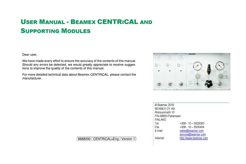
Table of contents
Other BEAMEX Test Equipment manuals

BEAMEX
BEAMEX MC6-WS User manual
BEAMEX
BEAMEX CENTRICAL User manual
BEAMEX
BEAMEX MC6 User manual

BEAMEX
BEAMEX FB150 User manual
BEAMEX
BEAMEX MC4 User manual

BEAMEX
BEAMEX MCS100 User manual
BEAMEX
BEAMEX MC6-Ex User manual
BEAMEX
BEAMEX TC305 User manual
BEAMEX
BEAMEX MC5-IS User manual
BEAMEX
BEAMEX PO8C User manual


