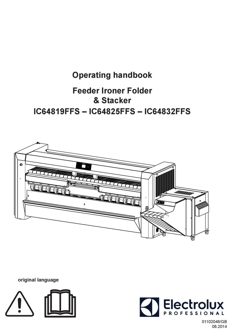
Electrolux Professional IC6 48 FFS Series User manual

Installation manual
Ironers
IC6 48xx FFS
Original language
10102059/EN


Contents
Contents
1 General instructions :...........................................................................................................................5
1.1 Environmental information..........................................................................................................5
1.2 Disposal information ..................................................................................................................6
1.2.1 Disposal of appliance at end of life .....................................................................................6
1.2.2 Disposal of packing ..........................................................................................................6
1.3 Preliminary instructions ..............................................................................................................6
1.3.1 Precautions for use...........................................................................................................8
1.3.2 Symbols ..........................................................................................................................9
1.3.3 Personal protection equipment ........................................................................................10
1.3.4 Emergency stop .............................................................................................................10
1.4 Data plate explanation.............................................................................................................. 11
1.5 Note about the A.C. power........................................................................................................15
1.6 Locking and tagging procedure .................................................................................................16
1.7 Working place lighting ..............................................................................................................17
2 Handling...........................................................................................................................................18
2.1 Unpacking...............................................................................................................................18
2.2 Lifting with a fork-lift truck .........................................................................................................18
2.3 Lifting with handlings straps......................................................................................................20
2.4 Moving along the ground .........................................................................................................20
2.5 Handling the stacker ................................................................................................................20
3 Installation : ......................................................................................................................................21
3.1 Installation...............................................................................................................................21
3.1.1 How to remove the pallet :...............................................................................................23
3.1.2 Levelling the machine : ..................................................................................................29
3.1.3 Machine with optional suction feeding table ......................................................................29
3.2 Remove of the transport locks fitted...........................................................................................30
3.2.1 Transport locks fitted inside the casing of the feeder : ........................................................30
3.2.2 Transport angles :..........................................................................................................31
3.2.3 Setting of flap : ...............................................................................................................32
3.3 Connection of the stacker .........................................................................................................34
3.4 Electrical connection ................................................................................................................36
3.4.1 Connection diagrams for the control circuit power supply (T2)............................................41
3.4.2 Operating inspection.......................................................................................................41
3.5 Connection of the ironer evacuation system : .............................................................................43
3.5.1 Fresh air inlet .................................................................................................................44
3.5.2 Evacuation duct .............................................................................................................45
3.5.3 Specifications :..............................................................................................................45
3.5.4 Exhaust pipes pressure control :......................................................................................46
3.5.5 Evacuation system if several dryers are connected to a common evacuation duct (except
gas heating machines):...................................................................................................47
3.6 Steam and condensate connections : ........................................................................................48
3.6.1 Steam connection DN 20 (3/4” BSP) : ..............................................................................49
3.6.2 Condensate connection DN 10 (3/8” BSP) : .....................................................................49
3.6.3 D.E.S.P. approval ..........................................................................................................50
3.7 Gas connection :......................................................................................................................51
3.7.1 Gas supply DN 20 (3/4” BSP) : ........................................................................................52
3.7.2 Determinate the gas type : ..............................................................................................53
3.7.3 Gas valve setting............................................................................................................53
3.7.4 Injectors setting..............................................................................................................53
3.8 Compressed air connection ......................................................................................................54
3.8.1 Standard connection.......................................................................................................54
3.8.2 Air compressor..............................................................................................................56
3.9 Check before use.....................................................................................................................57
3.9.1 Positioning roller rotation check .......................................................................................57
4 Appendices.......................................................................................................................................57
4.1 Packaging-Weight....................................................................................................................58
4.2 Technical characteristics...........................................................................................................58
4.3 Supplies..................................................................................................................................62
4.4 Sound level .............................................................................................................................62
4.5 Electric power supply : .............................................................................................................63
4.5.1 TABLE 1 (in accordance with EN standard 60204–1)........................................................63
4.5.2 TABLE 2 correction factors for different ambient temperatures : ........................................63

Contents
4.5.3 TABLE 3 correction factors for different cable insulating materials : ....................................64
4.5.4 TABLE 4 B2, C and E correction factors for cable grouping : ..............................................64
4.5.5 Calculation ....................................................................................................................64
4.5.6 Electrical Standard characteristics for IC6 48xx FFS .........................................................64
4.6 Gas setting characteristics IC6 48xx FFS : ................................................................................. 65
4.6.1 Legend of symbols used : ...............................................................................................66
4.6.2 Testing pressure :...........................................................................................................67
4.6.3 Setting gas adjustment :..................................................................................................68
4.6.4 Adjustment and checking of the outlet pressure ................................................................70
4.6.5 Tables of Correspondences :...........................................................................................72
4.7 Explanation of washing symbols ...............................................................................................74
4.7.1 Washing ........................................................................................................................74
4.7.2 Bleaching ......................................................................................................................75
4.7.3 Drying ...........................................................................................................................75
4.7.4 Ironing...........................................................................................................................75
4.7.5 Dry or water cleaning......................................................................................................76
4.8 Conversion of measurement units .............................................................................................77
The manufacturer reserves the right to make changes to design and component specifications.

Installation manual 5
1 General instructions :
Caution
All the illustrations in this manual do not necessarily represent your machine, but the action shown is always
compatible with your product!
1.1 Environmental information
Concerned by providing the end user with useful and necessary environmental information, we wish to precise:
• Data about energetic consumptions, wastes (atmospheric and liquid) and sound level are indicated in the para-
graph «Technical characteristics».
• Foreseeing its recycling, this machine is fully dismantable.
• This machine is free from any asbestos.
• In conformity with French regulations.
• In the other countries, we recommend that you comply with the legislation in force in the country where the ma-
chine is installed.
• In France, all owners of packing waste producing a weekly volume below 1100 litres can forward these to the local
collection and treatment department. If exceeding this volume, the owners of packing waste will ensure their valu-
ation by reuse, recycling or, any other action aiming at producing reusable materials or energy... or provide them
contractually to a certified intermediate authorised to transport, trade or broke waste.
Therefore, this forbid:
– land filling raw waste;
– open air burning or incineration without energy collection.
• Packaging of our machines are according with the french legislation related to environment requirements.
For additional information, do not hesitate to consult with our environmental department.
Scrapping of machine
When the machine is no longer to be used, it must be submitted to a recycling facility for destruction.
The majority of the components in the machine can be reused, but it also contains other materials that must be
taken care of in the correct way.
Therefore, never mix the machine or its parts with domestic waste as this may lead to health hazards or dam-
age to the environment.

6Installation manual
1.2 Disposal information
1.2.1 Disposal of appliance at end of life
Before disposing of the machine, make sure to carefully check its physical condition, and in particular any parts of
the structure that can give or break during scrapping.
The machine’s parts must be disposed of in a differentiated way, according to their different characteristics (e.g. met-
als, oils, greases, plastic, rubber, etc.).
Different regulations are in force in the various countries, therefore comply with the provisions of the laws and com-
petent bodies in the country where scrapping takes place.
In general, the appliance must be taken to a specialised collection/scrapping centre.
Dismantle the appliance, grouping the components according to their chemical characteristics, remembering that the
compressor contains lubricant oil and refrigerant fluid which can be recycled, and that the refrigerator and heat pump
components are special waste assimilable with urban waste.
The symbol on the product indicates that this product should not be treated as domestic waste, but must be correctly disposed
of in order to prevent any negative consequences for the environment and human health. For further information on the recy-
cling of this product, contact the local dealer or agent, the Customer Care service or the local body responsible for waste
disposal.
Note!
When scrapping the machine, any marking, this manual and other documents concerning the appliance
must be destroyed.
1.2.2 Disposal of packing
The packing must be disposed of in compliance with the current regulations in the country where the appliance is
used. All the packing materials are environmentally friendly.
They can be safely kept, recycled or burned in an appropriate waste incineration plant. Recyclable plastic parts are
marked as following examples.
PE
Polyethylene:
• Outer wrapping
• Instructions bag
PP
Polypropylene:
• Straps
PS
Polystyrene foam:
• Corner protectors
1.3 Preliminary instructions
Before any use, it is compulsory to read the instruction handbook.
Users must have learnt how the machine operates.
In order to prevent any risk of fire or explosion, flammable products should never be used to clean the machine.
This machine should be installed in conformance to the health and safety regulations, and only used in a sufficiently aerated area.
Check the instructions before installing or using the machine.
Caution
The mechanical and electrical installation of the machine should only be done by qualified personnel.

Installation manual 7
Do not use the machine unless it is plugged into a correctly earthed power socket complying with stand-
ards in force.
Caution
This device must not be installed in places accessible to the public.
Warning
Make sure the machine is disconnected from the mains before repairing or servicing.
Important
Any repairing or maintenance operation should be carried out by a specialist.
Important
The machine is delivered with a wall instructions paper to be clearly fixed near the machine.
Important
After the installation, Send back the commissioning form ,signed document, to Electrolux to validate the warranty
of the product.
Caution
Disconnect all sources of energy and let the ironing cylinder cool down before any intervention on the machine.
The high temperature of the ironing cylinder may cause serious burns ; avoid touching the hot surfaces.
Danger
Never iron if the finger protection does not function.
Important
The machines comply with the European Directive EMC (ElectroMagnetic Compatibility). They have been tested
in laboratory and approved as such. It is so prohibited to add wires or non shielded electric cables in the cabinets,
strands or cables’troughs.

8Installation manual
Important
It is specially advised not to install the machine on a synthetic floor covering. The frictional electricity
may hinder the good working of the machine
Under no circumstances should a gas-heating machine be installed in a building which includes a dry-
cleaning machine.
This is particularly important for your safety and that of others. The consequence is an immediate can-
cellation of the warranty.
Important
When using the machine in automatic folding mode, you could catch your fingers when the sheet remov-
al actuator ascends/descends with the anti-static device and in folding arm movements.
Do not operate on the machine without powering down beforehand.
Caution
For your own safety, it is prohibited and dangerous to solder the ironing cylinder. If a leak occurs, never
try to repair it yourself. Ask our technical departments for advice.
The machine can work without the protective casing when the electric supply is not cut off.
Interlock the main isolating switch with a padlock.
Close the steam inlet valves.
If you detect gas smells, turn off the gas, open the windows, do not activate any switch and warn the
maintenance service.
The warranty might be cancelled if these instructions are not complied with.
1.3.1 Precautions for use
• The machine should not be used by children.
• This ironer must be used exclusively for textiles appropriate for machine ironing, which have been previously and
exclusively washed in water.
• This machine is for professional use and must be used exclusively by qualified personnel.
• Blankets should not be ironed.
• Do not iron linen coated with solvent, paint, wax, grease or any easily inflammable products.
• In case of gas heated machine, do not assemble the machine on premises containing a dry cleaning machines or
other similar machines.

Installation manual 9
1.3.2 Symbols
Caution.
An exclamation mark inside an equilateral triangle offers the user important advice about usage, servicing, and hazard-
ous conditions
Caution, presence of dangerous current.
A flash lightning with an arrow at its end inside an equilateral triangle , warns the user about the presence of uninsu-
lated “dangerous current” sufficient in intensity to cause electrocution.
Caution, hot surface.
This symbols warns the user of the presence of high temperatures which could cause severe burns. Some surfaces
can reach close to 200°C (392°F).
Read the instructions before using the machine.
Warning, do not operate with casing removed.
This symbol warns the user that there are mechanisms inside the machine which can be dangerous. The protective
housing must be in place during use.

10 Installation manual
1.3.3 Personal protection equipment
Given below is a summary table of the Personal Protection Equipment (PPE) to be used
during the various phases of the machine’s service life.
Phase Protection
garments
Safety
footwear
Gloves Glasses Ear protectors Mask Safety helmet
Transport XO
Handling XO
Unpacking XO
Installation X O
Normal use X X X X
Adjustments OX
Routine
cleaning OX X O
Extraordinary
cleaning OX X O
Maintenance OXO
Dismantling OXO
Scrapping OXO
Legend :X: PPE required ; O: PPE available or to be used if necessary.
Normal use : Safety footwear must be defined for a use on a wet floor. And use glasses
and gloves to manipulate chemical products.
1.3.4 Emergency stop
The emergency stop must be unblocked, if not the machine will not work (to unblock, turn the red button to the right).
If the machine for some reason has to be stopped, abnormal or dangerous running, press the emergency sop button.
Release the emergency stop, by turning it clockwise only after checking what motivated this stop.

Installation manual 11
1.4 Data plate explanation
In this chapter, you will find the explanation of the different data input on the data plate of your product.
• Commercial name : Usual name of your product ( i.e. IC64819).
• Type : Type of your product (you have the same on the Declaration of Conformity CE if delivered with CE
certification).
• Model : Model of your product (can be different of commercial name ) .
• Serial Number : serial number of your product which indicate the week of the production of your product (the first 4
digit indicate the year and the week of production)
and the plant where it has been produced (finish by 17)
• Product N°: Product number of your product.
• Date : The date of the end of manufacture of your product
• Some technical data depending of the heating of your product : see list below :
• Some technical data depending of the voltage ordered.
the voltage looks like that 380–415V 3 50–60Hz
under this, you find the protection request for your product (i.e 16 A)
• Different logos are available on your data plate .
They represent the different certification obtained for your product
CE, EAC
ETL intertek for USA and Canada countries
• QR code : when you scan it, you will be able to obtain the full documentation for your product (Complete installa-
tion and user manuals)
• Standardized protection index of your product : IP24D

12 Installation manual
Electrical heating :
• P.Max : maximum power installed of your product
• Power of the motorization in kW and its isolation class (F) .
• Heating power in W .

Installation manual 13
Gas heating :
Left side
• P.Max : maximum power installed of your product
• Power of the motorization in kW and its isolation class (F) .
• Heating power in W .
• Gas approval number depending on your machine except ETL product (begin by1312/........)
Right side
• Qn (Hi) : heating power of your product
• Installed gas type , its pressure, its injector diameter and its consumption .
• Gas type for approval
• 3 Other gas type compatible with their pressure, their injectors diameter

14 Installation manual
Steam heating :
Left side
• P.Max : maximum power installed of your product
• Power of the motorization in kW and its isolation class (F) .
• Heating power in W .
Right side
• P.Maxi. (kPa) maximum pressure
For additional information, do not hesitate to consult with our quality department.

Installation manual 15
1.5 Note about the A.C. power
According to the EN 60204-1:1997 standard, the machine is provided for A.C. supplies corresponding to the ex-
tracted characteristics below :
4.3.2 A.C. supplies
Voltage:
Steady state voltage: from 0.9 to 1.1 of nominal voltage.
Frequency:
from 0.99 to 1.01 of nominal frequency continuously.
from 0.98 to 1.02 short time.
Harmonics:
Harmonic distortion not to exceed 10 % of the total r.m.s. voltage between live conductors for the sum of the second
through to the fifth harmonic. An additional 2 % of the total r.m.s. voltage between live conductors for the sum of the
sixth through to the 30th harmonic is permissible.
Voltage unbalance:
Neither the voltage of the negative sequence component nor the voltage of the zero sequence component in three-
phase supplies shall exceed 2 % of the positive sequence component.
Voltage interruption:
Supply interrupted or at zero voltage for not more than 3 ms at any random time in the supply cycle. There shall be
more than 1 second between successive interruptions.
Voltage dips:
Voltage dips shall not exceed 20 % of the peak voltage of the supply for more than one cycle. There shall be more
than 1 second between successive dips.

16 Installation manual
1.6 Locking and tagging procedure
A red insert at the beginning of this instruction handbook schematically shows the locking and tagging procedure de-
scribed below. If you wish, you can detach this insert and display it close to the machine to remind maintenance per-
sonnel of the safety instructions.
Always respect items 2, 3 and 4 carefully before doing any repair or maintenance work on
the machine.
Warning, begin this procedure when the ironer is cool down !!!
Put the main switch to Off
and lock the handle with a
padlock in one of the
three holes provided for
this purpose.
Close the stop valves for
the other supplies (steam,
gas, thermal fluid, com-
pressed air) to stop and
lock their handle with a
padlock.
Open the fixed protectors
(casings, doors) with the
key provided or a special
tool.
Do the maintenance.
Close and carefully lock the fixed protectors.

Installation manual 17
Unlock the stop valves and the main switch.
1.7 Working place lighting
The lighting should be designed so as to avoid eye strain for the operator ; it should be uniform without any glare,
and should be sufficient to detect any hazards.
The average lighting value on the working place recommended by the clothing industry for inspecting linen is 500 lux.
Whenever possible, the working place should be illuminated by daylight.

18 Installation manual
2 Handling
Important
It is obligatory that all these operations are undertaken by handling specialists.
2.1 Unpacking
You should have found an instruction handbook and keys to open the machine casings, in the machine.
Depending on its destination, the ironer is delivered bare or may be placed on a transport pallet and/or packed with
plastic film.
In some cases, it may be delivered in a crate, or in maritime packing (wood box).
Take off the plastic film or remove the wood with a spanner.
Caution
Check that no damage has been caused during transport.
2.2 Lifting with a fork-lift truck
Warning
You should never handle the machine in its longitudinal side (any other than shown on the drawing below) with a
fork-lift truck. Important risk of parts deterioration for those fixed under the machine.
This can be carried out from the front or back, and at the centre of the machine using forks with minimum length of
1.50 m (59”) and only with the pallet.

Installation manual 19

20 Installation manual
2.3 Lifting with handlings straps
Lifting in that case can only be done with handling straps (C : minimum capacity 2500 daN / L : minimum length 4m)
which bear weight of the machine.
Caution
Make sure to place the straps correctly to avoid any bending of parts of the machine.
Caution
In order to avoid any bending of casings, you should never climb and stand on top of the machine.
2.4 Moving along the ground
The machine frame is made up of two parallel spars, making ground moving possible by means of rollers, grinding
tracks or a trolley.
The two handling angles (B) can be used to lift the machine using hydraulic jacks or poles, so that rollers can be slip-
ped under the girder.
2.5 Handling the stacker
The stacker can be lifted using handling straps (C : minimum capacity : 500 daN ) able to support the weight of the
stacker.
The stacker can also be wheeled over a smooth flat surface using its 4 wheels (A).
Other manuals for IC6 48 FFS Series
1
This manual suits for next models
3
Table of contents
Other Electrolux Professional Iron manuals
