manuals.online logo
Brands
  1. Home
  2. •
  3. Brands
  4. •
  5. Electrolux
  6. •
  7. Ventilation Hood
  8. •
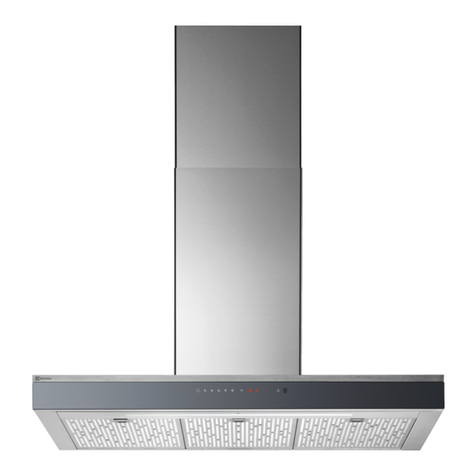
  9. Electrolux ICON E30WV60EPS User manual

Electrolux ICON E30WV60EPS User manual

]nsta]]atian Instructions
Vc_t l/ood
BEADANDSAVET SEIINS U DONS
[] [] [] [] [] [] [] [] [] [] [] [] [] [] [] [] [] [] [] [] [] []
Read all instructions before installing the hood.
For your safety, please read and observe all safety instructions. Thb guide will help
you antbipate all installation connections.
[] [] [] [] [] [] [] [] [] [] [] [] [] [] [] [] [] [] [] [] [] []
For toll-free telephone support in the U.S. and Canada:
1-877- 4ELEOTROLUX (1-877-435-3287)
For online support and lnternet product information:
www.eleet roluxusa.eom
@2005 EIectrolux Home Products, Inc.
Post Office Box 212378, Augusta, Georgia 30917, USA
All rights reserved. Printed in the USA
TABLE OF'CONTENT9
[] [] [] [] [] [] [] [] [] [] [] [] [] [] [] [] [] [] [] [] [] []
Finding Information ...........................................2
PleaseReadAndSaveThisGuide...................2
Questions..........................................................2
TableOfContents..............................................3
Safety ...................................................................4
ImportantSafetyInstructions..............................4
Preparing for installation ..................................7
VerifyingPackageContents...............................7
InstallationPlanning...........................................7
SpecificationsandDimensions...........................8
Exhaust Duct Locations....................................9
DuctLocations...................................................9
Duct Preparation................................................11
Cabinet Preparation .........................................13
PreparingtheCabinets....................................13
Electrical PowerSupply ...................................14
Requirements..................................................14
Installation ........................................................15
InstallingtheHood...........................................15
MakingtheEledricalConnection.....................16
Operation ...........................................................17
VerifyingtheOperation....................................17
IIM £NT S£FEW IINS U ONS
[] [] [] [] [] [] [] [] [] [] [] [] [] [] [] [] [] [] [] [] [] []
Safety Precautions
Do not attempt to install or operate your unit until you have read the safety
precautions in this manual. Safety items throughout this manual are labeled with a
Warning or Caution based on the risk type.
,5!:,,This is the safety alert symbol. It is used to alert you to potential personal injury
hazards. Obey all safety messages that follow this symbol to avoid possible injury
or death.
SAFETYPRECAUTIONS
VEB F'¥PACKAGECONTENTS
[] [] [] [] [] [] [] [] [] [] [] [] []
Use and Care Manual
,, Suction Cup
[] [] [] [] [] [] [] []
IIN
[] [] [] [] [] [] [] [] [] [] [] [] [] [] [] [] [] [] [] [] [] []
A qualified installer must complete the installation of this builtqn appliance. Proper
installation is your responsibility.
Carefully check the location where the hood is to be installed. The hood should be
placed for convenient access. Make certain that electrical power can be provided in
the selected location.
Plan the installation so that all minimum clearances are met or exceeded.
Dimensions shown provide minimum clearances, unless otherwise noted.
The specified minimum cabinet depth and width must be provided.
Cabinet cutout dimensions must be used as indicated. All contact surfaces
between the appliance and the cabinet must be solid and level.
Make certain that you have everything necessary to ensure a proper
installation before proceeding.
Overall Dimensions
Isometric View
(9" hood shown)
Figure 1
9" HoodOverall Dimensions
Model Width "A" Width "B"
E30WV60EPS 297/8" (759mm) 2313/16" (605ram)
E36WV60EPS 357/8" (911mm) 2313116"(605ram)
E48WV12EPS 477/8"(1216ram) 2313/16" (605ram)
Overall Dimensions
Isometric View
(18" hood shown)
Figure 2
Model Width "B"
E308WV60ES 2613/16" (681ram)
E368WV60ES 2613/16" (681ram)
E488WV126S 2613/16" (681ram)
18" HoodOverall Dimensions
Width "A"
297/8" (759mm)
357/8" (911mm)
477/6"(1216mm)
Verticam Exhaust Duct Location
E3OWV6OEPS, E36WV60EPS, E308WV6OES,
E368WV60ES
Top View
Figure 3
6 1/8"
(156mm)
t
8" (203ram)
Round Duct
Collars
Vertical Exhaust Duct Location
E48WV12EPS
Top View
Figure 5
Horizontal Exhaust Duct Location
E488WV120S
Rear View
Figure 7
Horizontal Exhaust Duct Location
E308WV60ES, E368WV60ES
Rear View
Figure 6
f \ \
/\ \\
\\ \\
\ \
\ \
\\
5304449697
Custom Transition
for use with
E488WV120S
(not included) Figure 8
EL,,EC CAL,CONDUT IIIL,,,,,,,OCAT ONS
[] [] [] [] [] [] [] [] [] [] [] [] [] [] [] [] [] [] [] [] [] []
1 1/2" 1/2"
7/8"_ (11Pqm) Holes (_8 _!_)m_rl
Conduit Location
E3OWV6OEPS, E36WV60EPS, E48WV12EPS,
E3OSWV6OES, E368WV60ES, E488WVI20S
Top View
9" and 18" Hoods
Figure 9
Conduit Location
E308WV6OES, E368WV60ES, E488WV120S
ReadBack View
18" Hoods
Figure 10
Electrical Conduit Locations
Model No. Dimension "A" Conduit Location
E3OWV6OEPS 9" (752mm)
E308WV6OES
E36WV60EPS 8" (203ram}
E368WV60ES
E48WV12EPS 147/16"(367mm}
E488WV120S
Refer to the table beUow for recommended maximum straight Rengths of duct to
provide adequate performance.
Model Duct Maximum Equivalent Straight Lengths
Size
10" 50'
31/4"x10" 50'
E3OWV6OEPS
E36WV60EPS
E48WV12EPS
E3OSWV6OES
E368WV60ES
E488WV120S
E3OWV6OEPS
E36WV60EPS
E3OSWV6OES
E368WV60ES
60'
Refer to the table beUow for recommended sheet metaU eUbows, transitions, and
wall cap equivaUent straight Rengths.
Recommended sheet metal elbows, transition, and wall cap equivalent straight lengths
3 1/4" x 10" 900 Elbow
15 Feet
Transistion
3 1/4" x 10" to Round
8" Diameter - 4 Feet
10" Diameter - 4 Feet
3 1/4" x 10" 45 Elbow
7 Feet
3 1/4" x 10" Wall Cap
2 Feet
45 ° Elbow - Round Duct
8" Diameter -3 Feet
10" Diameter - 2 Feet
90 o T ransistion
3 1/4" x 10" to 8" Round
25 Feet
3 1/4" x 10"
90 ° Flat Elbow
20 Feet
90° Elbow -Round Duct
8" Diameter -7 Feet
10" Diameter -5 Feet
IP PABINGTHEC£B N
[] [] [] [] [] [] [] [] [] [] [] [] m [] [] [] [] [] m [] m
Minimum hood clearances are zero inches (0") to the rear, sides and top of the
hood.
Thirty inches (30") is the minimum distance between the bottom of the hood and
any cooking surface.
Maximum effective cUearance from cooking surface to bottom of hood is 36"
(914mm).
[] [] [] [] [] [] [] [] [] [] [] [] [] [] [] [] [] [] [] [] [] []
It is the owner's responsibility to ensure that the electrical connection of this
appliance is performed by a qualified electrician. The electrical installation including
minimum supply wire size and grounding, must be in accordance with the latest
revision of the National Electric code ANSI/NFPA and local codes and ordinances.
A copy of this standard may be obtained from:
National Fire Protection Association
1 Batterymarch Park
Quincy, Massachusetts 02269-9101
The correct 120VAC, 60Hz, 15A circuit must be supplied for this appliance from a
separate, grounded, circuit that is protected by a properly sized circuit breaker or
time delay fuse.
IINIWAI,,,,,,,,,,I,,,,,,,,,,INGTIE HOOD
[] [] m m m m [] [] [] [] m m m [] [] [] [] m m m m []
First temporarily mount a 2x4 ledger board 30" (762mm) from the finished
countertop. Then, remove the filters from the hood canopy and remove the shields
below the power ventilator. Secure the hood through the keyhole slots in the top of
the hood and/or the slot hole in the rear of the hood. Remove the temporary ..... .......: .......
support ledger.
Top
mounlnc Rear
(both sides) holes
Temporary
supportledger
Temporacy Support Ledgec Instalation
(g" Shown)
Figure 11
Top
mountin(
(both sides)
Figure 12
MAKINGTHEELEC C£L CONNECTION
[] [] [] [] [] [] [] [] [] [] [] [] [] [] [] [] [] [] [] [] [] []
Figure 13 Electrical power source wiring can be
connected through the top or back of the
hood. Access the wiring inside the hood
canopy in the area to the right side of the
power ventilator.
Connect the pre=wJred 12" long black, white
and green wires to the corresponding
black, white and ground (green) wire from
the power source wiring. Use wire nut
connectors to secure the connections.
VE :'¥1NGTHEOPERATION
[] [] [] m m m [] [] [] [] m m m [] [] [] [] m m m m []
@
@
@
o
install the fiRers.
Verify that the hood control knobs are in the OFF position.
Turn on the main power supply.
The hood has two knobs that control the function of the hoods Halogen
lights and the exhaust blower. Turning the knobs clockwise will turn on
the lights and the blower. The blower has a variable speed range between
settings.

Other manuals for ICON E30WV60EPS

2

This manual suits for next models

5

Other Electrolux Ventilation Hood manuals

Electrolux EFC 90700 User manual

Electrolux

Electrolux EFC 90700 User manual

Electrolux EFC 9461 User manual

Electrolux

Electrolux EFC 9461 User manual

Electrolux EFP 629 User manual

Electrolux

Electrolux EFP 629 User manual

Electrolux EFC 9490 User manual

Electrolux

Electrolux EFC 9490 User manual

Electrolux EFC90400X User manual

Electrolux

Electrolux EFC90400X User manual

Electrolux EFL10566DX User manual

Electrolux

Electrolux EFL10566DX User manual

Electrolux EFF55680BX User manual

Electrolux

Electrolux EFF55680BX User manual

Electrolux ICON E40PV100FS User manual

Electrolux

Electrolux ICON E40PV100FS User manual

Electrolux PLHV42P8CC User manual

Electrolux

Electrolux PLHV42P8CC User manual

Electrolux EFT7041W User manual

Electrolux

Electrolux EFT7041W User manual

Electrolux EFT 60233 User manual

Electrolux

Electrolux EFT 60233 User manual

Electrolux DD 8891 Specification sheet

Electrolux

Electrolux DD 8891 Specification sheet

Electrolux EI30DD10KS User manual

Electrolux

Electrolux EI30DD10KS User manual

Electrolux LFU9215W User manual

Electrolux

Electrolux LFU9215W User manual

Electrolux EFI 60011 User manual

Electrolux

Electrolux EFI 60011 User manual

Electrolux EFC 9430 User manual

Electrolux

Electrolux EFC 9430 User manual

Electrolux C240 Specification sheet

Electrolux

Electrolux C240 Specification sheet

Electrolux EFC 630 User manual

Electrolux

Electrolux EFC 630 User manual

Electrolux EFC 9440X User manual

Electrolux

Electrolux EFC 9440X User manual

Electrolux EFV60656OW User manual

Electrolux

Electrolux EFV60656OW User manual

Electrolux LFL219X User manual

Electrolux

Electrolux LFL219X User manual

Electrolux DF 6160 Specification sheet

Electrolux

Electrolux DF 6160 Specification sheet

Electrolux LFP539X User manual

Electrolux

Electrolux LFP539X User manual

Electrolux LFG615X User manual

Electrolux

Electrolux LFG615X User manual

Popular Ventilation Hood manuals by other brands

Pkm 9031 instruction manual

Pkm

Pkm 9031 instruction manual

Teka DSB 90 instruction manual

Teka

Teka DSB 90 instruction manual

Bertazzoni K90HD2X installation instructions

Bertazzoni

Bertazzoni K90HD2X installation instructions

AEG CHDE 3160 operating instructions

AEG

AEG CHDE 3160 operating instructions

NEFF D 79T7 Series Operating and installation instructions

NEFF

NEFF D 79T7 Series Operating and installation instructions

Zline Attainable Luxury Alpine Series Installation guide and user's manual

Zline

Zline Attainable Luxury Alpine Series Installation guide and user's manual

GUTMANN LLANO TYP EM 32 operating instructions

GUTMANN

GUTMANN LLANO TYP EM 32 operating instructions

Whirlpool RH2000 Series installation instructions

Whirlpool

Whirlpool RH2000 Series installation instructions

KitchenAid KHLU182MSS1 parts list

KitchenAid

KitchenAid KHLU182MSS1 parts list

Franke FTC 532L GR/XS user manual

Franke

Franke FTC 532L GR/XS user manual

Solt GGSRC60 user manual

Solt

Solt GGSRC60 user manual

Siemens LF456CA30 Instructions for use

Siemens

Siemens LF456CA30 Instructions for use

Faber HIGH-LIGHT Series Installation instructions; use and care information

Faber

Faber HIGH-LIGHT Series Installation instructions; use and care information

Whirlpool Ventilation Hood Installation and use guide

Whirlpool

Whirlpool Ventilation Hood Installation and use guide

Hoover HBVS685TX user manual

Hoover

Hoover HBVS685TX user manual

Samsung NK24M1030IS/UR Installation instruction guide

Samsung

Samsung NK24M1030IS/UR Installation instruction guide

Smeg KSE920X instruction manual

Smeg

Smeg KSE920X instruction manual

Thermador CHMHP366W installation instructions

Thermador

Thermador CHMHP366W installation instructions

manuals.online logo
manuals.online logoBrands
  • About & Mission
  • Contact us
  • Privacy Policy
  • Terms and Conditions

Copyright 2025 Manuals.Online. All Rights Reserved.