Electron E-COAT Master User manual

Powder Coating Equipment Kits User’s Manual
E-COAT Master
User’s Manual

2
© 2017 Sistem Teknik Makina A.Ş.
All rights reserved.
10010 St. No: 10
35470
İTOB Menderes
Izmir TURKEY
No part of this document may be reproduced or transmitted in any form or by any means, electronic or mechanical, for any purpose, without the express written
permission of Sistem Teknik Makina San. Ve Tic. A.Ş. Under the law, reproducing includes translating into another language or format.
As between the parties Sistem Teknik Makina San. Ve Tic. A.Ş. retains title to, and ownership of, all proprietary rights with respect to the software contained within
its products. The software is protected by International copyright laws and international treaty provision. Therefore, you must treat the software like any other
copyrighted material (e.g. a book or sound recording).
Every effort has been made to ensure that the information in this manual is accurate. Sistem Teknik Makina San. Ve Tic. A.Ş. is not responsible for printing or clerical
errors. Information in this document is subject to change without notice.

3
Table of Contents
1- Safety Regulations ...................................................................................................................................................... 4
1-1 Safety Symbols .............................................................................................................................................. 4
1-2 Conformity of Use ......................................................................................................................................... 4
1-3 Technical Safety Regulations for Stationary Electrostatic Powder Spraying Equipment ....................................................... 5
1-3-1 General Information ............................................................................................................................... 5
1-3-2 Consciously Working Safe ......................................................................................................................... 5
1-3-3 Safety Regulations for the Operating Firm and/or Personnel ................................................................................ 5
1-3-4 Special Type of Hazards ........................................................................................................................... 6
1-3-5SafetyRequirementsforElectrostaticPowderCoating............................................................................................6
1-4 Product Specic Safety .................................................................................................................................... 7
1-5 Scope of Delivery ......................................................................................................................................... 7
1-6 Conformity Between Products ........................................................................................................................... 8
2- Technical Data ............................................................................................................................................................ 8
2-1 Electrical Data ............................................................................................................................................ 8
2-2 Pneumatic Data ......................................................................................................................................... 9
2-3 Powder Paint Output References ..................................................................................................................... 9
2-4 E-COAT Master with E-FEED V2 Output ................................................................................................................. 9
2-5 E-COAT Master Air Flow Rates ........................................................................................................................... 9
2-6 General View ............................................................................................................................................. 9
2-7 Front Panel and Input Buttons ........................................................................................................................ 10
2-8 Back Panel and Connections .......................................................................................................................... 11
2-9 General Instructions .................................................................................................................................... 12
3- Start Up ........................................................................................................................................................................15
3-1 Installation................................................................................................................................................. 15
3-2 Start Up ................................................................................................................................................... 18
3-3 Operation ................................................................................................................................................. 19
3-4 Trigger ..................................................................................................................................................... 24
3-5 Fluidization ............................................................................................................................................... 24
4- Cleaning and Maintenance .................................................................................................................................. 25
5- Troubleshooting ....................................................................................................................................................... 25
6- Parts and Accessories ........................................................................................................................................... 27
7- Service and Maintenance Table .......................................................................................................................... 60
8- Product Life and Warranty ................................................................................................................................... 61

4
1. Safety Regulations
This section sets out the fundamental safety regulations that must be followed by the user and third parties using the E-COAT
Master. These safety regulations must be read and understood before the E-COAT Master is used.
1.1. Safety Symbols
The following warnings with their meanings can be found in the Sistem Teknik Makina operating instructions. The general safety
precautions must also be followed as well as the regulations in the operating instructions.
DANGER!
Live electricity or moving parts are dangerous.
Possible Consequences: Death or serious injury.
WARNING!
Improper use of the equipment could damage the machine or cause it to malfunction.
Possible consequences: Minor injuries or damage to equipment
1.2. Conformity Of Use
• E-COAT Master Manual Coating Equipment is built to the latest specication and conforms to the recognized technical
safety regulations. It is designed for the normal application of powder coating.
• Any other use is considered as non-conform. The manufacturer is not responsible for damage resulting from improper use
of this equipment; the end-user alone is responsible. If the E-COAT Master is to be used for other purposes or other substances
outside of our guidelines then Sistem Teknik Makina A.Ş. should be consulted.
• Observance of the operating, service and maintenance instructions specied by the manufacturer is also part of
conformity of use. The E-COAT Master should only be used, maintained and started up by trained personnel, who are informed
about and are familiar with the possible hazards involved.
• Start-up is forbidden until it has been established that the E-COAT Master has been set up and wired according to the
guidelines for machinery EN 60204-1 (machine safety) must also be observed.
• Unauthorized modications to E-COAT Master exempt the manufacturer from any liability from resulting damage.
• Relevant accident prevention regulations, as well as other generally recognized safety regulations, occupational health
and structural regulations are to be observed.
• In addition to above, country-specic safety regulations must be observed.
Note:EN 60204-1 this standard includes the non-mobile machines electronic machines and
programmable electronic hardware and systems.
Explosion Protection Protection Type Temp Class
II 3 D IP54
Explosion Protection Protection Type Temp Class
II 2 D IP64
Explosion Protection Class of E-COAT Master Controller Unit
Explosion Protection Class of E-GUN C1 Powder Paint Gun
Explosion Protection Protection Type Temp Class
II 2 D IP64
Explosion Protection Class of E-GUN C3 Powder Paint Gun

5
1.3. Technical Safety Regulations for Stationary Electrostatic Powder Spraying Equipment
1.3.1. General Information
The powder spraying equipment of Sistem Teknik Makina (Electron) is designed for safe use and to the latest technological specs.
Electrostatic powder equipment could create dangerous situations unless it’s used properly. In addition to that, there might be a
danger to life and limb of the user or third party, a danger of damage to the equipment and other machinery that belongs to the
user and hazards to the proper operation of equipment.
• The powder spraying equipment should only be started up and used once the operating instructions have been carefully
read. Apart from any usage from the user manual, there lies a danger of damaging the equipment and loss of control of the
equipment.
• Operational safety has to be observed before every start-up. Regular Servicing is the essence of working safely.
• Local legislation should be considered for the safety.
• The plug has to be disconnected before the machine is opened for repair.
• The plug and socket connections between spraying equipment should only be taken out when the power is off.
• The connection cables have to be installed in a manner that they wouldn’t interfere or damage the normal machine
operation. Also the local legislation should be observed for the installation.
• Only original Electron spare parts should be used, because only the original products will guarantee the equipment’s
explosion protection. Any damage caused by other used parts is not covered by the guarantee.
• If Electron powder spraying equipment is going to be used with other devices/machinery from other manufacturers, their
safety regulations should be also considered.
• Be cautious while working in a powder/air mixture area. In the right concentration the mixture would be ammable, thus
smoking is forbidden in the entire plant area.
• Rule of thumb says that any person who uses a pacemaker should NEVER enter a high voltage area or places with
electromagnetic elds. Note that people with pacemakers ALSO SHOULDN’T work in powder spraying installations.
WARNING!
Only the customer itself is responsible for the safe usage of the equipment
Sistem Teknik is not responsible for any damage resulted from the usage.
1.3.2. Consciously Working Safe
Every other individual who will be working for the assembly, start-up, operation, service and repair of powder spraying equipment
must have read and understood the operating instructions and the “Safety Regulations”. Operators have to be appropriately trained
via Sistem Teknik assembly personnel and made aware of the possible danger of powder spraying equipment and the environment.
The control units for guns must only be set up and used in zone 22. The spray guns are permitted in the zone 21 which is created
by them but only them.
Powder spraying equipment must only be used by trained and authorized personnel. This also applies for any kind of modication
to the electrical equipment, which only should be carried out by a specialist.
It is essential that the operating instructions are understood before any kind of work is done with the equipment. All the procedures
have to be done according to the instructions.
Powder spraying equipment can be turned off via the main power switch or the emergency shut down procedure.
1.3.3. Safety Regulations for the Operating Firm and/or Personnel
• First of all, anything which would inuence the equipment negatively should be avoided for the technical safety.
• The machine user should be well informed about no other people than trained personnel would use the machine.
• The employer has to provide an operating instruction manual for specifying the dangers for humans and the environment by
handling dangerous materials, as well as all preventive measures and workplace behaviors. This “document” must be well
written in an understandable form in the language that the person employed for the equipment.
• The operator is obliged to check the equipment for external damage once every shift changed at the very least. The operation
characteristic changes should also be reported.
• Users should conform the satisfactory working conditions else the equipment should not be used.
• The operating rm must ensure that the users wear protective clothing like facemasks and working suits.
• The rm also guarantees the cleanliness of the workplace and proper checks for the powder spraying equipment.
• Safety devices should be always on the equipment at all costs unless the equipment is going to be maintained or cleaned. After
the maintenance all the devices should be put on the equipment. The users must be trained well for this purpose.
• 9. Powder uidization or high voltage spray gun checks have to be done when the equipment is switched on.

6
1.3.4. Special Types of Hazard
• Power: All the high voltage equipment should be unplugged before opened. This is a huge life risk thus it has to be taken under
great care.
• Powder: Powder/air mixtures could be ignited by sparks. Sufcient ventilation is a must while using powder spraying equipment.
Powder, which is not swept from the oor creates risky environment.
• Static Charges: These could result in the following: Charges to people, electric shocks, sparks. Charging of objects has to be
avoided.
• Grounding: All electricity conducting parts and machinery in the workplace must be earthed 1.5 mt on either side and 2.5
mt around each booth opening. The grounding resistance must amount to a maximum of 1 MOhm resistance has to be tested
regularly. The appropriate devices must be kept in the workplace for regular grounding checks.
• Compressed Air: Compressed air could be created after long pauses of the equipment and this creates risk of pneumatic hose
damage or uncontrolled release and improper use of compressed air. Compressed air should be drained properly.
• Crushing and Cutting: There might be moving parts while operation (e.g. Conveyor Belt, Reciprocator). The operator must be
trained to maintain the area safety and local security regulations.
• Exceptional Circumstances: Local conditions must be met at all costs. Additional measures such as barriers can be used to
prevent unauthorized access.
• Conversions and Modications to the Equipment: All conversions and modications must be asked to Sistem Teknik prior to
the process and no process should be done without Sistem Teknik’s permission. This is essential for the equipment safety and
conformity. Powder coating equipment should never be used if damaged; these parts should be changed immediately with
the original Sistem Teknik replacement. Other replacements then Sistem Teknik original equipment does not conform the
guarantee, thus the guarantee will no longer be valid. Equipment repairs must be done only by specialist or at Sistem Teknik
veried shops.
1.3.5. Safety Requirements for Electrostatic Powder Coating
• All the equipment used for powder coating is dangerous unless the instructions are not conformed.
• Every electrostatic conductive part must be earthed within the 5 meter radius from the equipment.
• The oor of the coating area should conduct electricity (Concrete is generally a conductive surface, check with your building
project for more info)
• The users should wear electricity conducting footwear.
• The guns are earthed thus you must use them with your bear hands. If gloves are going to be used, make sure that they conduct
electricity.
• Grounding cable must be connected to the grounding screw of the electrostatic powder spraying hand appliance. It should
have a good connection with the booth, hopper and conveyor chain (if used).
• E-COAT Master Device must be switched off while the hand gun is being cleaned.
• The grounding must be checked every week. Remember that the grounding resistance must be 1 MOhm at a maximum.
• The E-COAT Master equipment should only be switched once the booth is working in proper conditions. If the booth malfunctions,
E-COAT should be turned off.
• At nozzle changes, the E-COAT Master device should be shut down.
• Only use spare parts / attachments and accessories from Sistem Teknik’s original parts page. This ensures the safety of the
equipment and conformity of use.
• Cleaning agents creates the risk of hazardous fumes. Please check the manufacturer’s manual about more information about
the cleaning agents if they are used in the site.
• If there is any damage on the powder coating equipment or the spray gun, operators should stop using it.
• Especially make sure that the environmental regulations and the manufacturer’s instructions are being conformed while
disposing the powder lacquer and cleaning agents.
• Repairs have to be carried out via specialists of Sistem Teknik trained personnel and never to be done in the operating area
under any circumstance.
• Dangerous dust concentration levels should be avoided in powder spraying areas. There must be sufcient technical ventilation
available (e.g. booth ventilation) to prevent a dust concentration of more than %50 of the lower explosion limit (UEG = max.
permissible powder/air concentration). If the UEG is not known then a value of 10g/m3 should be used.

7
2. E-COAT Master Manuel Bare Kit 3. E-COAT Master H
EN European Standarts
1.4. Product Specic Safety
If there is an installation work that will be done by the customer, the local regulations have to be considered.
The plant must be checked for any type of foreign objects inside the booth or in ducting, input and exhaust air before start up.
All equipment must be grounded according to the local regulations before start up as well.
1.5.
Scope of Delivery
1. E-COAT Master Automatic Bare Kit
94/9/EC The approximation of the laws of the Member States
relating to apparatus and safety systems for their
intended use in potentially explosive atmospheres
EN 12100-1 EN 12100-2 Machine safety
EN IEC 60079-0 Electrical equipment for locations where there is
danger of explosion
EN 50 050 Electrical apparatus for potentially explosive atmos-
pheres - electrostatic hand-held spraying equipment
EN 50 177 Stationary electrostatic spraying equipment for
ammable coating powder
EN 12981
Coating plants - spray booths for application of
organic powder coating material - safety require-
ments
EN 60 529 IP-Type protection: contact, foreign bodies and
water protection for electrical equipment
EN 60 204
VDE regulations for the setting up of high voltage
electrical machine tools and processing machines
with mains voltages up to 1000 V
• E-GUN C3
• E-GUN C3 Automatic Gun Cable (12 m)
• E-FEED V2
• E-COAT Master
• Regulator and Air Distribution Unit
• Hose connection accessories
• E-GUN C1
• E-FEED V2
• E-COAT Master
• Regulator and Air Distribution Unit
• Hose connection accessories
• E-GUN C1
• E-FEED V2
• E-COAT Master
• E-HOPP 50
• E-COAT Mobile Carrier w/ Air
Distribution Unit and Fluidization
Control
• Hose connection accessories

8
4. E-COAT Master M
1.6. Conformity Between Products
• E-GUN C1
• E-FEED V2
• E-COAT Master
• E-COAT Multicolor Unit w/ Vibratory
Box Holder and Suction Tube
• Hose connection accessories
Electron E-GUN C1 can be used with:
• E-COAT Master
• E-FEED V2
• FastCorona™ Manual
Electron E-GUN C3 can be used with:
• E-COAT Master
• E-COAT Pro
• E-FEED V2
• FastCorona™ Auto
Electron E-COAT Master can be used with:
• E-GUN C1
• E-GUN C3
• E-FEED V2
2. Technical Data
E-COAT Master Control Unit
Nominal Input Voltage 100-240 VAC
Operating Frequency 50-60 Hz
Input Power 60 VA
Gun Nominal Output Voltage Max. 20 Vp-p
Gun Nominal Output Current Max. 1,5 A
Auxiliary Output Type 24 VDC/max. 10W, 100-240 VAC/max.100W
Purge Output Type 24 VDC, max. 10W
Protection Class IP54
Max. Operating Surface Temp 85°C
Certication II 3 D
2.1. Electrical Data

9
E-COAT Master Control Unit
Powder Paint Type Epoxy / Polyester
Powder Hose Type Double Carbon De charge Connection Antistatic Hose
Powder Hose Length 5 m
Powder Hose Diameter 11 mm
Powder Air Nozzle Diameter 1,5 mm
E-COAT Master Control Unit
Compressed Air Connection 8 mm
Input Pressure 5,5-7,0 bar
Max. Water Vapor in Compressed Air 1,4 g/m3
Max. Oil Vapor Content in Compressed Air 0,12 mg/m3
2.2. Pneumatic Data
2.3. Powder Paint Output References
E-COAT Master Control Unit
Total Air (lt/min)
50 75 100
% Paint Powder Output (gr/min)
20 5 10 25
40 25 60 130
60 60 165 240
80 130 240 307
100 185 290 360
2.4. E-COAT Master with E-FEED V2 Output
2.5.
E-COAT Master Air Flow Rates
2.6. General View
E-COAT Master Control Unit
Nozzle Air 0-16 lt/min (2 lt/min Factory Set.)
Supplementary Air 10-75 lt/min
Conveying Air 10-100 lt/min
Total Air 20-175 lt/min
1) Front Panel
2) Display and Control Buttons
3) Casing
4) Back Panel and I/O
10
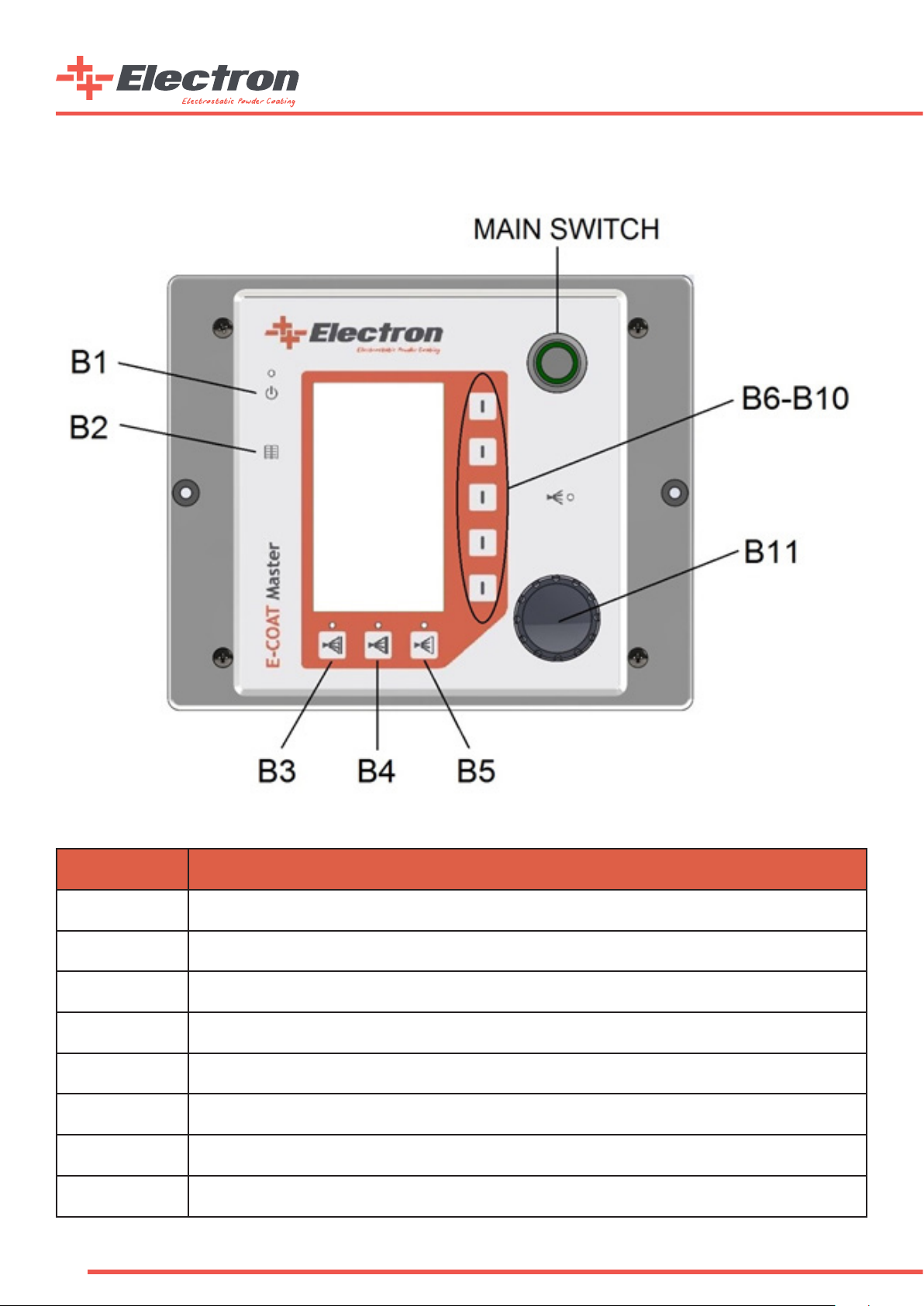
2.7. Front Panel and Input Buttons
Button Denition
B1 Fluidization and Vibration Motor(Only Multicolor) Active/Passive Button
B2 Menu Button
B3 Automatic Program 1
B4 Automatic Program 2
B5 Automatic Program 3
B6-B10 Segment Buttons
Main Switch Main Power Switch
B11 Rotary Adjustment Knob

11
2.8. Back Panel and Connections
CONNECTION FUNCTION
1.0 POWER IN MAIN POWER CONNECTION (100-240VAC, 50-60Hz)
1.2 Fuse 1.6A Glass Fuse Holder 1.6A
1.3 TCP/IP (Optional) TCP/IP automation serial connection RJ45 (Optimal for automatic device congurations)
1.4 GUN Gun Cable Connection
1.5 AUX Fluidization Unit/Multicolor Unit Connection
1.6 PURGE (Optional) Purge Valve Connection (Supplied with optional Purge Module)
MAIN AIR IN 5.5-7 BAR Main Pressured Air Connection (5,5-7,0 Bar, Ø8 Hose)
Nozzle Air Connection (Black Ø6 Hose)
Supplementary Air Connection (Blue Ø8 Hose)
Powder Air Connection (Red Ø8 Hose)
Earth Cable Connection
Warning: AUX input lid should be closed if there is no connection.
PIN Connection
1) Phase (100-240 VAC)
2) Neutral
3) Trigger (Phase Applied-Only Automatic Mode)
PE) Grounding
Back Panel Connections
Back Panel Connection Table
12
2.9. General Instructions
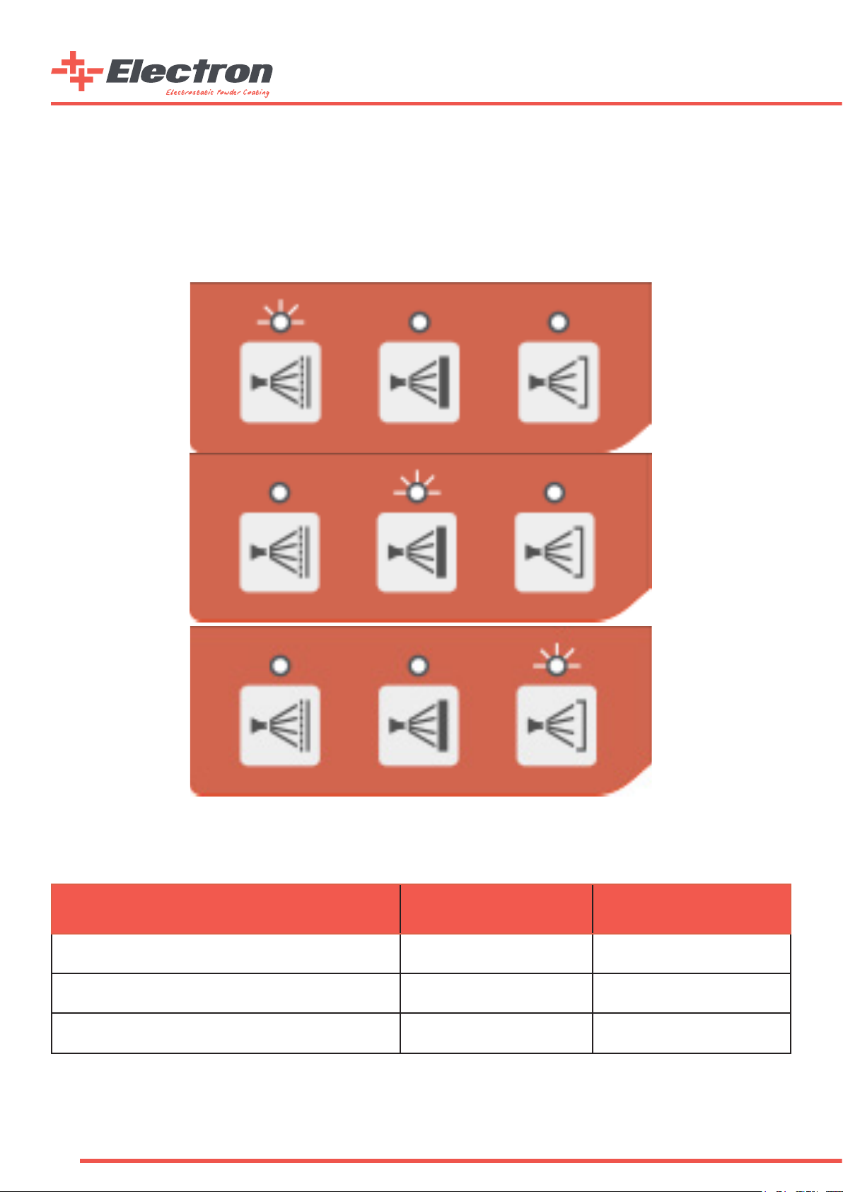
Usage Types
a. Automated Recipe Working Mode
This type of usage allows the customer to work with custom made recipes as well the three predened recipes stated below:
1. Coating on Straight Faced Materials
2. Coating on Coated Materials
3. Coating on Notched Surfaces
Predened Recipe Buttons
Predened Recipe Working Parameters
Predened Recipe Name High Voltage (kV) Output Current (µA)
Coating on Straight Faced Material 100 100
Coating on Coated Material 100 10
Coating on Notched Surfaces 100 22
13
b. User Dened Recipe Working Mode
In this working principle, the user can save their own working parameters and change them. There can be 4500 recipes starting
from P01 to P50, three of which P01-02-03 are factory predened recipes. These predened recipes are explained in this manual.
Users can manually dene 47 different recipes of their choice.
Recipe Segment
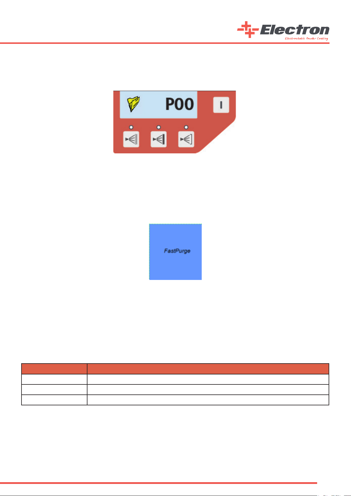
c. Fast Purge Mode
Fast Purge mode uses the high pressured air to clean the Injector, Antistatic Coating Hose and E-GUN Coating Path. A “FastPurge”
sign will appear on the main screen of the E-COAT Master when Fast Purge mode of the device is activated. E-COAT Master Device’s
Fast Purge mode can be activated by two different ways.
a. By pressing and holding the Page Button (B2 Button) for 3 seconds.
b. By pressing and holding the “P” button on the manual E-GUN C1 gun for 3 seconds.
Fast Purge Mode Screen
Fast Purge mode’s working scenerio alters depending on the device conguration. The Fast Purge mode stays on for 10 seconds
and rinses through the hose and gun automatically If the E-COAT Master device is congured as “Auto”. On the other hand, the gun
trigger on the E-GUN C1 works as a valve trigger during the Fast Purge mode if the E-COAT Master device is congured as a manual
device (Hopper or Multicolor). The air comes out from the Purge Unit if the trigger is pressed and stop if the trigger is released.
The E-COAT Master device exits from the Fast Purge mode if the trigger is not pressed for 3 seconds or the “P” button on the back
side of the E-GUN C1 is pressed once during Fast Purge mode.
d. Remote Control with E-GUN C1
The user can change the system parameters on E-COAT Master via using the E-GUN C1. The buttons which are marked “P”, “^”
and “ˇ” are explained below
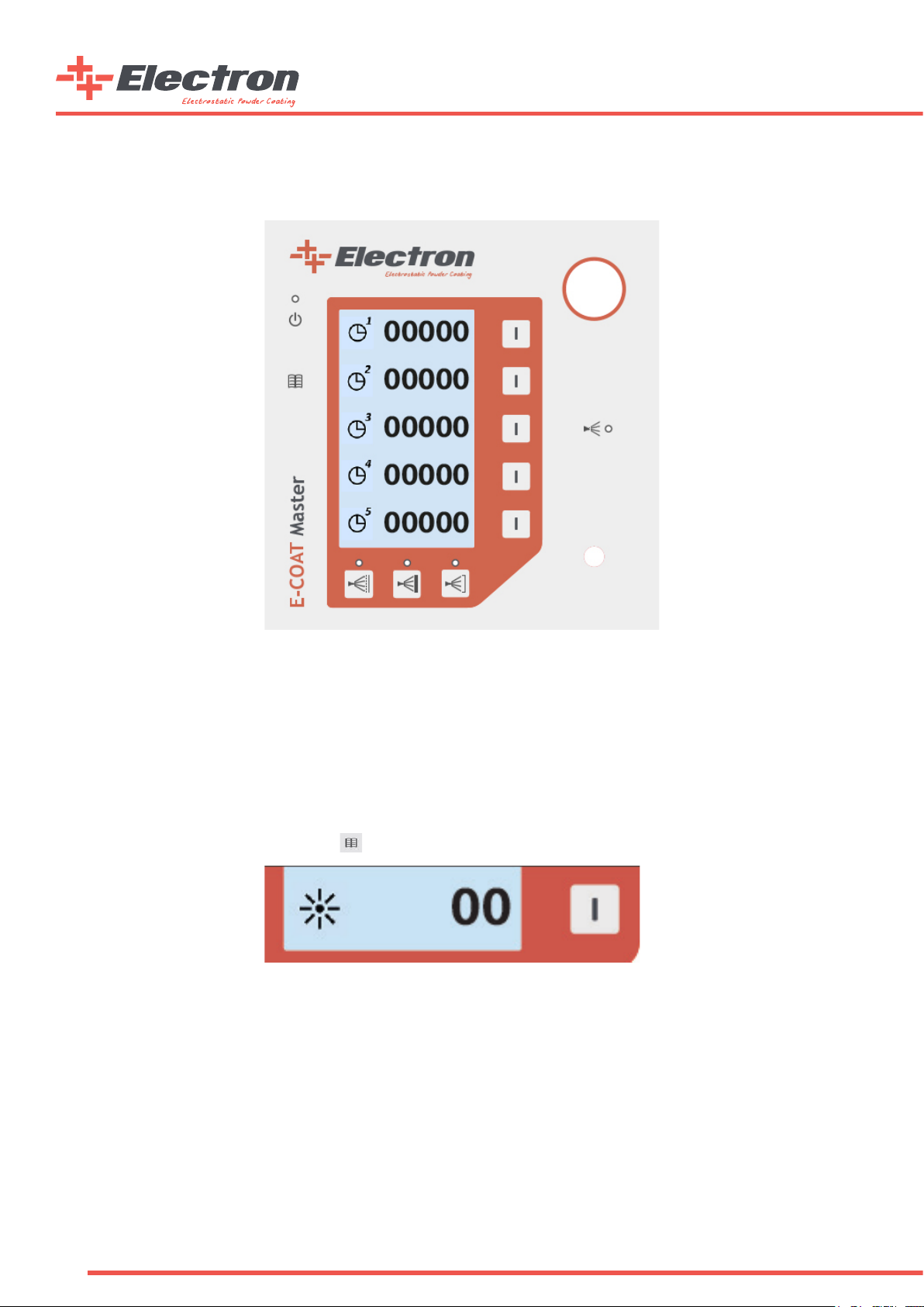
e. Consumable Counters
E-COAT Master is designed with consumable counters so that the use would be always aware of the materials.
You can open the counter via pressing the B2 button for two times.
Button Function
PRecipe, Powder Ratio, Powder Air with consecutive presses - Fast Purge (via pressing 3 seconds)
Value decrease
Value increase
v
v
14
The user can also adjust the counters to create a warning when the consumables are about to nish or when they are nished.
See the counters on the screen below.
Consumable Counters Screen
The user can differentiate between consumables and adjust ve different consumables on the screen. The counters will warn the
user when they reach to zero if they are not reset. A “!” sign will lit and blink on the bottom of the main page when a counter has
reached to “0” and the counter is not reset by entering into the counters page for acknowledgement. The blinking “!” sign will
disappear from the screen when user enters to the counters page to acknowledge the counter alarm. The unit of the counters are
“Days”.
f. Screen Brightness Adjustment
E-COAT Master electrostatic powder paint control unit screen brightness can be adjusted by the user. The LCD screen allows the
user to change the brightness from the segment button shown below in the second part of the Main Page. Reaching to the second
part of the Main Page is from pressing the B2 button once.
Part-2 Screen Brightness Segment
The screen brightness can be adjusted between the values 0 to 10, 0 showing the lowest brightness and 10 showing the highest.
Info: E-COAT Master control unit is installed with standby mode. If the buttons are not used on the control unit or on the E-GUN, the
control unit changes the brightness level to 0. Any input while in standby mode switches the control unit to the normal mode and the brightness
becomes to the normal level

15
3. Start Up
3.1. Installation
a. “Bare” and “H” type Device Kits Electro-Pneumatical Connections

16
b. “M” type Device Kits Electro-Pneumatical Connections

17
c. “A” type Device Kits Electro-Pneumatical Connections

18
3.2. Start Up
Info: E-COAT Master Powder Coating Control unit always starts with the last used conguration preferences.
In the above “System Connections” gure, all the electrical and pneumatic connections are shown. After correctly connecting the
device, the user can press the “Main Switch” to start the control unit. The below procedure should be done at the rst Start up.
E-COAT Master should be calibrated according to the products that are going to be powder coated before the start up. Once you
are in the “Main Page” Press the B1 interface button for 5 seconds and the Congurations Page 1 will appear a. The Conguration
Pages are ve pages in total and by pressing B2 button the user can cycle through them. The user can switch to the “Main Page”
by pressing B1 button once.
Info: If the control unit is not used or a button is not pressed for 15 seconds time, the control unit automatically goes
back to the “Main Page”.
The available calibrations for the “Calibration Pages” are stated in the below table
Code Code Info Preferences Factory Preset
C-1 Control Type Selection
0 = Automatic
1 = Manual w/ Hopper
2 = Manual w/ Multicolor
1
C-2 Gun Type 0 = Corona
1 = Tribo 0
C-3 AUX output latency after trigger release (s) 0-100 10
C-4 Pneumatical Control Type 0 = Proportional
1 = Independent 0
C-5 Pneumatical Flow Units 0 = lt/m
1 = Nm3/h 1
C-6 Purge Valve Opt. 0 = Disabled
1 = Enabled 0
C-7 Gun Cable Length (m) 5-25 5
PCF1 Min. Powder Corr. Factor (lt/m) 0 - 50 5
PCF2 Powder Output Corr. Factor 0 - 100 100
Calibration Preferences
Info: Correction Factors should be adjusted from the “Correction Factors Adjustment Table” below.

19
3.3. Operation
a. Creating and Saving a User Recipe:
Recipe Segment
After adjusting the values from the control unit, the user can save the recipe for future usage. To save the current recipe, press
and hold the segment button next to the recipe segment button for three seconds. You will see the recipe number ashing every
500ms. The user then chooses the recipe number for the current recipe. Turn the knob until the desired recipe number is selected.
Once the number is selected the recipe can be saved.
To save the recipe, press and hold the same segment button for three seconds. This time, the screen will start ashing every 200ms
for 2 seconds and the recipe will be saved successfully. If instead of pressing and holding for three seconds, the user presses the
button, the current recipe will not be saved and the screen will turn to its rst position.
b. Predened Recipe Usage
Predened Recipe Recall Buttons
Pressing the rst predened recipe on the left side calls the at surface coating application. After pressing, the screen automatically
brings the P01 recipe and the LED indicator will light up. Similarly, if the user presses the button on the middle, the control unit
brings up the P02 recipe which is the “Coating on Coated Surface”, and if the user presses the right button the “Coating on Notched
Surface”. Recipe will be recalled and the proper LED will light up.

20
Predened Recipe Working Parameters are located below
Predened
Recipe Name High Voltage (kV) Current (µA)
Flat Surface Application 100 100
Coating on Coating Application 100 10
Notched Surface Application 100 22
High Voltage Preferences:
There are two different methods in E-COAT Master to change the High Voltage and Gun Output Current. These are as follows:
1. Using the front panel interface of E-COAT Master
2. Using the E-GUN C1 Manual type back side interface.
As it is shown in the below gures, the values can be changed on the rst two segment buttons. Once the value
segment is selected, the user can adjust the values via rotating the knob on the device
High Voltage and Current Adjustment Segments
The adjustments set the upper limits of both the High Voltage and Current Values. The values can change while gun operation,
according to the coating application, and the type of workpiece. These values will also change according to the length between the
workpiece and the tip of the gun. Once the gun is triggered the values can be read on the same segment. The “Orange” coloured
parts show the adjusted values on the selected recipe and the “Black” coloured numbers show the real time usage values.
Info: The upper limit of the High Voltage is 100kV and the current output limit is 100µA.
Air and Powder Adjustments:
There are two different pneumatic control types of E-COAT Master powder coating device.
These are;
1. Control via the Total Air and Powder Ratio
2. Control via Independent Air Flow
Picking the rst option, the user should adjust the value in regards to the air/powder ratio. The total output air per unit time
should be calculated and the total powder per unit time should be adjusted accordingly.
Table of contents
Other Electron Paint Sprayer manuals

Popular Paint Sprayer manuals by other brands

Gema
Gema OptiFlex Pro F Operating instructions and spare parts list

Spraying Systems
Spraying Systems AutoJet 1000+ owner's manual

paasche
paasche A-AU Automatic Spray Gun operating instructions

wiwa
wiwa HERKULES PFP Operation manual

Enduraplas
Enduraplas ICEMASTER LIQUID MASTER T Series owner's manual

Sealey
Sealey HVLP-79/P.V2 instructions


