Telex Communications RTS TIF 4000 Instruction Manual
TIF 4000
Technical Data Sheet TIF 4000
Description
Architectural & Engineering
specifications
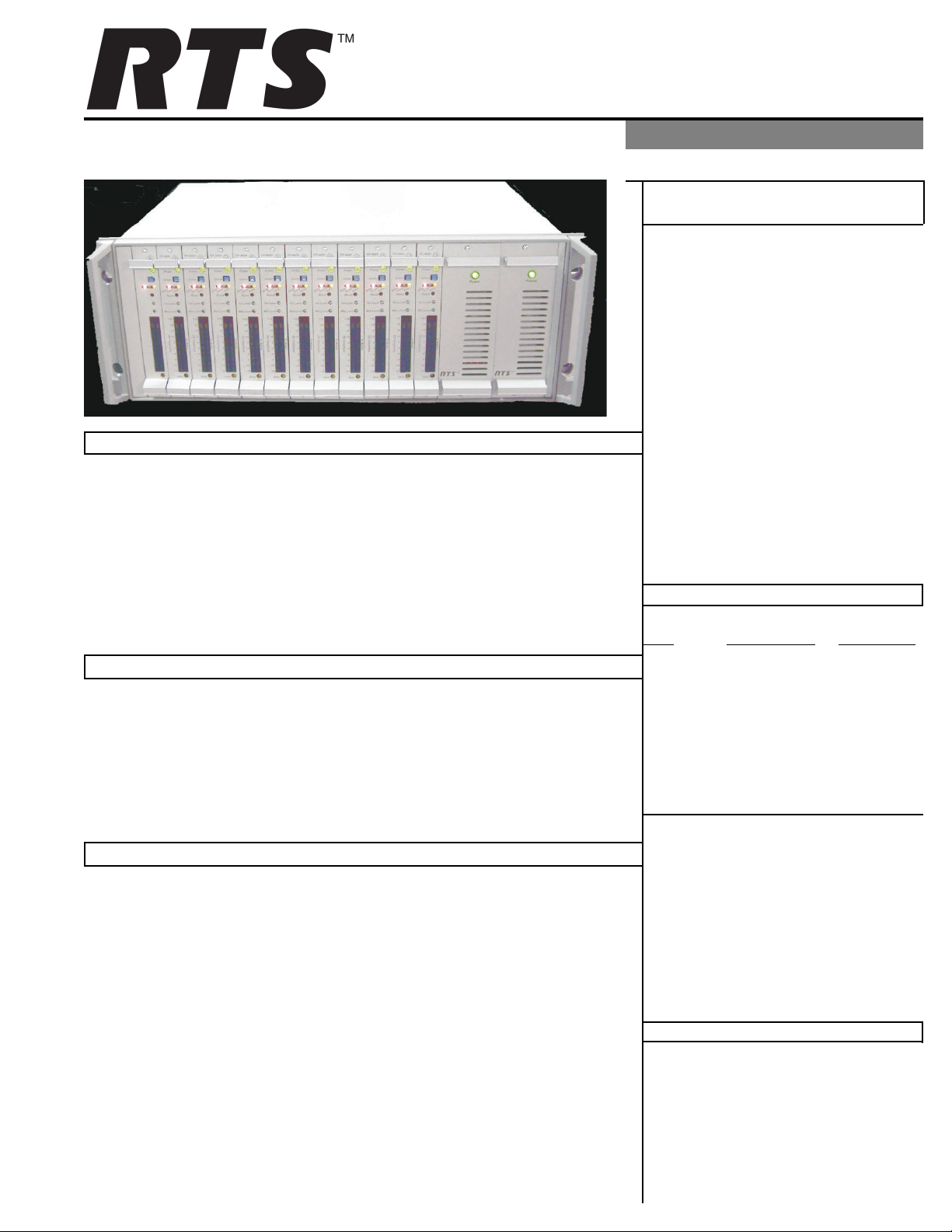
The TIF 4000 is a frame capable of up to 12 digital telephone interface cards
with a redundant power supply designed to be compatible with ADAM,
ADAM CS, and ZEUS intercom systems. It provides bi-directional communica-
tion between the intercom matrix and a standard DTMF capable telephone line.
It allows the phone to access all crosspoints of the matrix, as well as dynamic
party lines, IFB circuits, and other forms of communications. The 4RU high
TIF 4000 provides a transparent link to the telephone system enabling full dial-
out capability from any designated keypanel with keypad. Since the TIF 4000
appears to the matrix as any other keypanel would, the only limitation on the
number of units in the system is the same as for other keypanels.
Features
The unit shall provide full functionality of
an RTS matrix keypanel via a DTMF tele-
phone line interface. The unit shall be com-
patible with telephone systems world
wide. The unit shall be capable of manual
and auto answer with user selectable se-
curity and password. It shall provide a dial
out capability from other keypanels. The
unit shall be 4RU tall. It shall be capable
of being mounted in a standard equipment
rack via optional mounting kits. It shall
provide a means via the front panel for
setting audio levels for both the telephone
line and the matrix connections. It shall
provide a means for upgrading its internal
firmware via a download from the system.
Please Contact Us
Telex Communications, Inc.
12000 Portland Avenue South
Burnsville, MN 55337 U.S.A.
Tel: (800) 392-3497
Fax: (800) 323-0498
• Redundant Power supply
• 12 TIF frame ina 4RU space
• Auto or manual answer
• Select security code or none
• Select number of rings before answer
• Caller can be locked to one matrix point
• Up to 16 panels may be selected to ring
• Call in directly to party line or IFB
Applications
• Simplex or full duplex IFB
• Remote IFB.
• Remote PL from ENG/SNG
• Remote studio tie-in
• Remote diagnostics
• Aerospace multi-system link
• Sports venue multiple PL tie-in
• Olympic or concurrent sports IFB
• Caller may select up to seven T/L assignments
• Caller may change presets
• Auto disconnect
• Direct audio input mixes w/ matrix audio
• Levels can be adjusted for intercom and phone
• Downloadable telephone system configuration
38110-423 Rev B 02/2005
Ordering Information
Item Part Number Description
TIF 4000
(frame) 9000-7812-000 TIF
4000 Frame
TIF 4000
(card) 9020-7818-000 TIF
4000 Front
Card
Copyright © 2004 Telex Communications, Inc. Printed in U.S.A.
Specifications Front Panel Features
Warranty
Matrix Input/Output:
0 dBu to +20 dBu
Telephone Input/Output:
-30 dBu to +6 dBu
Noise (200 Hz to 3.8 kHz):
-40 dBu or less
Harmonic Distortion
(300 Hz to 3.8 kHz):
Intercom Side: -30 dBu or less
Telephone Side: -25 dBu or less
Frequency Response:
300 Hz to 3.8 kHz +0 dB, -6 dB
Matrix Connectors:
DB-9 Female
RJ-11 Female
Telephone Line Connector:
RJ-11
Telephone Loop-Thru Connector:
RJ-11
Power Requirements:
Universal Power Supply
100-240VAC,
50/60Hz
Card Power Every card uses
1Amp of power
Power Dissipation
TIF-4000 Full Frame (12 TIF
Cards)
750mA @ -15V
1A @ +15V
9A @ +5V
TIF-4000 Individual Card
60mA @ -15V
70mA @ +15V
750mA @ +5V
Environmental:
Operating Temperature:
-4°F to122°F (-20°C to 50°C)
Storage Temperature:
-22°F to 158°F (-30°C to 70°C)
Dimensions:
19” W x 6.97” H x 12.8” D
(25.4mm W x 177.038mm H x
325.12mm D)
Weight:
28.45 lbs. (12.9047 kg)
RTS™ products are warranted by Telex Communications, Inc. to be free from defects in materials and workmanship for
a period of three years from the date of sale.
The sole obligation of Telex during the warranty period is to provide, without charge, parts and labor necessary to
remedy covered defects appearing in products returned prepaid to Telex. This warranty does not cover any defect,
malfunction or failure caused beyond the control of Telex, including unreasonable or negligent operation, abuse, acci-
dent, failure to follow instructions in the manual, defective or improper associated equipment, attempts at modification
and repair not authorized by Telex, and shipping damage. Products with their serial numbers removed or effaced are not
covered by this warranty.
This warranty is the sole and exclusive express warranty given with respect to RTS products. It is the responsibility of the
user to determine before purchase that this product is suitable for the user’s intended purpose.
ANYAND ALL IMPLIED WARRANTIES, INCLUDING THE IMPLIED WARRANTY OF MERCHANTABILITY
ARE LIMITED TO THE DURATION OF THIS EXPRESS LIMITED WARRANTY.
NEITHER TELEX NOR THE DEALER WHO SELLS TELEX PRODUCTS IS LIABLE FOR INCIDENTAL OR
CONSEQUENTIAL DAMAGES OF ANY KIND.
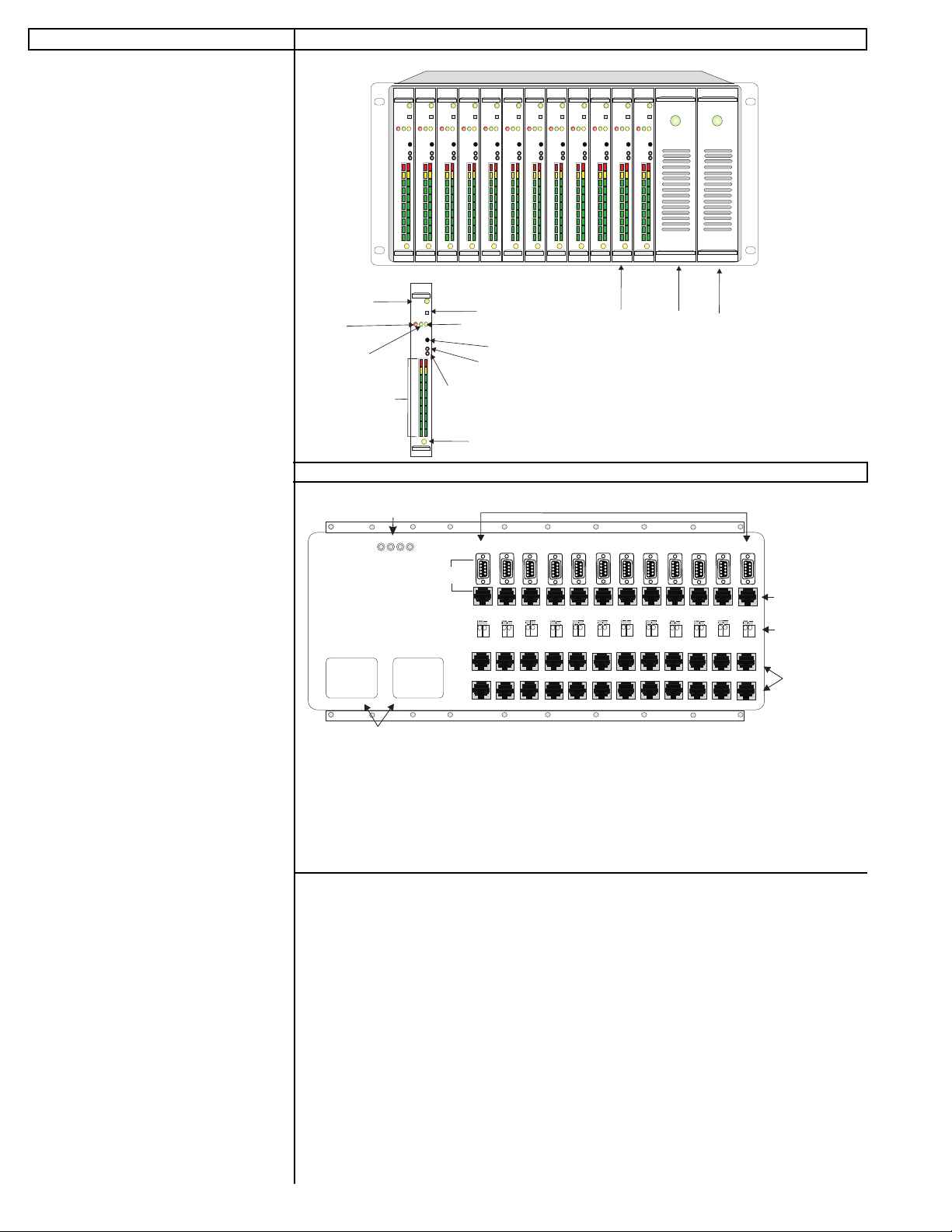
Rear Panel Features
POWER
DATA
TEL LEVEL
MTX LEVEL
DROP
RESET
AUTO
SEIZE
SELECT
+12
+9
+6
-15
-6
-9
-12
+3
0
-3
TO TELEPHONE
TO MATRIX
POWER
DATA
TEL LEVEL
MTX LEVEL
DROP
RESET
AUTO
SEIZE
SELECT
+12
+9
+6
-15
-6
-9
-12
+3
0
-3
TO TELEPHONE
TO MATRIX
POWER
DATA
TEL LEVEL
MTX LEVEL
DROP
RESET
AUTO
SEIZE
SELECT
+12
+9
+6
-15
-6
-9
-12
+3
0
-3
TO TELEPHONE
TO MATRIX
POWER
DATA
TEL LEVEL
MTX LEVEL
DROP
RESET
AUTO
SEIZE
SELECT
+12
+9
+6
-15
-6
-9
-12
+3
0
-3
TO TELEPHONE
TO MATRIX
POWER
DATA
TEL LEVEL
MTX LEVEL
DROP
RESET
AUTO
SEIZE
SELECT
+12
+9
+6
-15
-6
-9
-12
+3
0
-3
TO TELEPHONE
TO MATRIX
POWER
DATA
TEL LEVEL
MTX LEVEL
DROP
RESET
AUTO
SEIZE
SELECT
+12
+9
+6
-15
-6
-9
-12
+3
0
-3
TO TELEPHONE
TO MATRIX
POWER
DATA
TEL LEVEL
MTX LEVEL
DROP
RESET
AUTO
SEIZE
SELECT
+12
+9
+6
-15
-6
-9
-12
+3
0
-3
TO TELEPHONE
TO MATRIX
POWER
DATA
TEL LEVEL
MTX LEVEL
DROP
RESET
AUTO
SEIZE
SELECT
+12
+9
+6
-15
-6
-9
-12
+3
0
-3
TO TELEPHONE
TO MATRIX
POWER
DATA
TEL LEVEL
MTX LEVEL
DROP
RESET
AUTO
SEIZE
SELECT
+12
+9
+6
-15
-6
-9
-12
+3
0
-3
TO TELEPHONE
TO MATRIX
POWER
DATA
TEL LEVEL
MTX LEVEL
DROP
RESET
AUTO
SEIZE
SELECT
+12
+9
+6
-15
-6
-9
-12
+3
0
-3
TO TELEPHONE
TO MATRIX
POWER
DATA
TEL LEVEL
MTX LEVEL
DROP
RESET
AUTO
SEIZE
SELECT
+12
+9
+6
-15
-6
-9
-12
+3
0
-3
TO TELEPHONE
TO MATRIX
POWER
DATA
TEL LEVEL
MTX LEVEL
DROP
RESET
AUTO
SEIZE
SELECT
+12
+9
+6
-15
-6
-9
-12
+3
0
-3
TO TELEPHONE
TO MATRIX
Power to board
LED indicator (green) Line Dropped
switch - disconnects
the line when pressed.
Line dropped
LED indicator
(red)
Line Siezed
LED indicator
(green)
Auto Answer
LED indicator
(amber)
POWER
DATA
TEL LEVEL
MTX LEVEL
DROP
RESET
AUTO
SEIZE
SELECT
+12
+9
+6
-15
-6
-9
-12
+3
0
-3
TO TELEPHONE
TO MATRIX
Board Reset
Level Adjustment
Pot for
Audio To the Line
Level Adjustment
Pot for
Audio To the Matrix
Data LED Indicator
(amber)
Front Card Power
Supply
Power
Supply
POWER POWER
To Matrix and To Telephone line
level indicator. The
level increments 3dB.
Phone
Line
Loop
Thru
Relay
To Matrix
90-240 VAC 90-240 VAC
-15 +5 COM +15
Test Jacks
For Testing
Purposes Only
DB-9 Connectors
to the Matrix
RJ-12 Connectors
to the Matrix
Terminal Block
RJ-11 Connectors
AC Power Input
12345678910 11 12
This manual suits for next models
2
Popular Recording Equipment manuals by other brands


Toa
Toa E 131 Operating instructions manual

INFOSEC UPS SYSTEM
INFOSEC UPS SYSTEM PFS 7 TCGE User instruction

Art
Art Xdirect Specifications

Roland
Roland VS8F-3 Workshop manual

elobau
elobau 363 Series Translation of the original operating instructions

Evolution Controls
Evolution Controls EVO/ECM-Modbus Application guide