ELECTRONIC ASSEMBLY EA KIT160-6 User manual

EA KIT160-6
ZEPPELINSTRASSE 19
·
D- 82205 GILCHING
TEL 08105/778090
·
FAX 08105/778099
·
http://www.lcd-module.de
04.2011
Touch Panel
optional
EA KIT160-6LEDTP
Dimension 102 x 80 x 36mm
Viewing area 70 x 36 mm
CONTROL PANEL WITH FONTS,
GRAPHICS COMMANDS AND MACROS
TECHNICALDATA
*LCD GRAPHICS DISPLAY WITH DIVERSE GRAPHICS FUNCTIONS AND FONTS
*160x80PIXELSWITH LED ILLUMINATION
*BLACK, SNAP-IN HOUSINGWITH ANTI-GLARE SCREEN ORTOUCH PANEL
*FONT ZOOM FROMapprox. 2.5mm VIAapprox. 5mm TOapprox. 35mm
*SUPPLYVOLTAGE OF 5V/400mA OR OPTIONALLY 9..35V
*BLUE-WHITEVERSION120mA/5V ONLY
*RS-232 OR OPTIONALLY RS-422WITH BAUD RATES OF 1200..115200 BD
*POSITIONINGACCURATE TOTHE PIXELWITH ALL FUNCTIONS
*PROGRAMMINGBY MEANSOF HIGH-LEVELLANGUAGE-TYPE COMMANDS:
*STRAIGHT LINE, POINT, AREA, AND/OR/EXOR, BAR GRAPH...
*UP TO 256 MACROS PROGRAMMABLE
*COMBINATIONS OFTEXT AND GRAPHICS
*PULL-DOWN MENUS
ACCESSORIES
*INTEGRATEDTOUCH PANELWITH8x4 FIELDS (ANTI-GLARE, SCRATCH-RESISTANT)
*FLOPPY DISK FOR MACRO PROGRAMMING (PC DOS):EA DISK240
*CABLE (1.5m) FOR CONNECTING TO 9-PIN SUB-D (RS-232 FEMALE):EA KV24-9B
ORDERDESIGNATION
160x80 DOTSWITH LED ILLUMINATION GB/GN EA KIT160-6LED
160x80 DOTSWITHTOUCH PANEL, LED ILLUMINATION, GB/GN EA KIT160-6LEDTP
BLUE-WHITEWITHTOUCH PANEL EA KIT160-6LWTP
SUPPLYVOLTAGE 9..35V INSTEAD OF 5V EA OPT-9/35V
RS-422 INSTEAD OF RS-232 EA OPT-RS4224
also avalable in
blue-white

2
EA KIT160-6
*) also available at http://www.lcd-module.de/deu/disk/disk240.zip
GENERAL
The EA KIT160 is a fully assembled control and operating unit with a variety of integrated functions. The
display has very compact dimensions and offers excellent super-twist contrast, which means the unit can
be put into operation immediately. It is controlled via the standard RS-232 or RS-422 interface. In addition
to complete graphics routines for display output, the operating unit also contains a wide variety of fonts.
Graphics commands similar to high-level language are used for programming. There is no longer any
need for the time-consuming programming of character sets and graphics routines. The ease of use
offered by macros and input via touch panel make it a real power display.
HARDWARE
The control panel is designed to work with an operating voltage of +5V. A supply voltage of 9..35V is also
possible. Serial asynchronous data transfer is carried out in RS-232 or RS-422 format. The transmission
format is set permanently to 8 data bits, 1 stop bit, and no parity. Rates between 1,200 baud and
115,200 baud can be selected using a PC. RTS and CTS handshake lines are available.
Data format:
TOUCH PANEL
The EA KIT160-6 LEDTP version is equipped with an integrated touch panel. You can make entries and
menu settings by touching the display. The labeling of the „keys“ is flexible and can also be changed
during runtime (different languages, icons). The drawing of the individual „keys“ and the labeling or
grouping of several fields is handled by the integrated software.
SOFTWARE
The control panel is programmed by means of commands, such as
Draw a rectangle from (0,0) to
(64,15)
. No additional software or drivers are required. Strings can be placed withpixel accuracy. Text
and graphics can be combined at any time. Up to 16 different character sets can be used. Each one can
be zoomed from 2 to 8 times. When the 8-times zoom is used with the largest character set (16x8), the
words and numbers displayed will fill the screen (= 128x64).
SETTING THE CONTRAST
The contrast of the display is set by means of the integrated potentiometer and remains constant across
the entire temperature range as a result of the on-board temperature compensation. If required, you can
connect an external potentiometer (25 kOhm) at the eyelets (J11). The solder straps LB 6 and LB 7 must
be open (see page 4).
ACCESSORIES
Floppy disk for macro creation
A floppy disk (EA DISK240) is required for macro programming*). This converts the commands entered
in a text file into a code that can be read by the operating unit, and programs them into the EEPROM.
Cable for PC
To enable simple connection to PCs (macro programming), we provide a 1.5m cable and a 9-pin SUB-
D female connector (EA KV24-9B). Simply insert it into COM 1 or COM 2 and get started. Note: The
cable is not suitable for the RS-422 version EA OPT-RS4224.

3
EA KIT160-6
Matrix Keypad Connector J4
Pin Symbol Funktion
1OUT 1 Output Column 1
2OUT 2 Output Column 2
3OUT 3 Output Column 3
4OUT 4 Output Column 4
5IN 1 Input line 1
6IN 2 Input line 2
7IN 3 Input line 3
8IN 4 Input line 4
9IN 5 Input line 5
10 IN 6 Input line 6
11 IN 7 Input line 7
12 IN 8 Input line 8
Application Example
Exampel Transmitted codes Remarks
for Compiler #* 11, 21, ´A´, 2, "STOP" Number of texts will be not
noted here !
ASC II ESC * . .A..S T O P . Point ´.´ stands for not
displayable ASCII-characters
Hex $1B $2A $0B $15 $41 $02 $01 $53 $54 $4F $50 $00
Decimal 27 42 11 21 65 2 1 83 84 79 80 0
Command
for Touch
Touch field
top left corner
Touch field
bottom right corner
Return
Code
Draw Frame
1-line-text
Text
terminator
EXTERNAL KEYBOARD(EA KIT160-6LED ONLY)
A keyboard (anything from individual keys to an 8x4 matrix keyboard) can
be connected at the plug-in connection J4. The connected keys are
debounced by means of software. Please note that it is only possible to
connect an external keyboard to the EA KIT160-6LED version without an
integrated touch panel.
Each key is switched between an output and an input. Each input has a
100kΩpullup. Up to 8 keys can be connected at each output.
Transmitting the keystrokes
At each keystroke, the associated key
number (1..32) is transmitted. The release of
the key is not transmitted. If the release of the
key is to be transmitted as well, this can be done by defining touch macro
no. 0. The automatic keyboard scan can be deactivated by means of the
„ESC T A 0“ command.
The key number can be determined as follows:Key number = (output
-1) * 8 + input (output: a number between 1 and 4, input: between 1
and 8).
Note: If the handshake line (e.g. CTS) does not permit transmission,
keystrokes can be lost.
TOUCH PANEL(EA KIT160-6LEDTP ONLY)
The EA KIT160-6LEDTP version is equipped with an integrated touch panel with 32 fields. The ontrol
panel offers convenient commands supporting this touch panel. It is possible, for example, to group a
number of touch fields to form a single large key and then draw and label the key. You can also assign
a return code (1..255) to the key you have defined. If a return code of 0 is assigned, the key is disabled
and has no effect when pressed.
When the touch keys are touched, they can be automatically inverted and a tone can sound, indicating
they have been touched. At the same time, the defined return code of the key is transmitted via the serial
interface, or an internal touch macro with the number of the return code is started.
Example:
Definition of a key from field 11 to 21 with the return code 65=´A´ and the
text „STOP“. Note: Before individual keys are defined, all fields should be
disabled by means of „ESC T R“.

4
EA KIT160-6
RS-422 Connector J3
Pin Symbol Function
1VDD +5V, Supply
2Data In - Receive Data
3Data In + Receive Data
4Data Out - Transmit Data
5Data Out + Transmit Data
6HS In - Handshake
7HS In + Handshake
8HS Out - Handshake
9HS Out + Handshake
10 GND 0V, Ground
*)
also available at http://www.lcd-module.de/disk/disk240.zip
RS-232C connector J3
Pin Symb In/Out Function
1VDD -+ 5V Supply
2DCD -Via LB 4 to DTR
3DSR -Via LB 3 to DTR
4TxD Out Transmit Data
5CTS In Clear To Send
6RxD In Receive Data
7RTS Out Request To Send
8DTR -See Pin 2, Pin 3
9NC -Not Connected
10 GND -0V Ground
J5 add-on
Pin Symbol In/Out Function
1VU -9..35V supply
2VDD -+ 5V supply
3GND -0V, ground
4TxD5 Out Transmit data (5V)
5RxD In Receive data (5V)
6RTS Out Request to send
(5V)
7CTS In Clear to send (5V)
8RESET In H: reset
9NC -not connected
10 NC -not connected
ATTENTION
handling precautions!
SUPPLY 5V / (9-35V)
In the standard model, the supply voltage of +5V is fed in via screw-type terminal J1.Alternatively, the 5V
can also be fed in at the 10-pin connector J3 (pin 1: 5V; pin 10: 0V) for the RS-232 interface.
In the case of the version for 9V to 35V (EA OPT-9/35V), the power is supplied via J2.
Important: It is imperative that the polarity is correct. Even very brief polarity reversal can damage the
display immediately and irreparably.
RS-232/RS-422 CONNECTION
The operating unit is shipped with an RS-232 interface as standard. The pin assignment of connector
J3 is then as shown in the table on the left. J3 has a grid of 2.54mm. If the operating unit is ordered together
with the EA OPT-RS4224 option, special RS-422 drivers are fitted. The pin assignment in the table on
the right then applies.
Incidentally, the same serial data with 5V
levels and TTL logic is available at the J5
eyelet strip. These levels are suitable for
direct connection to a µC. If these signals
are used, the solder straps LB 10 and LB
11 must be opened (or the four RS422
75176 drivers removed)!
BAUD RATES
The baud rate is set in the factory to 9600. You can use the program KITBAUD.EXE (available on
EA DISK240*)) to configure it. To do this, you have to connect the KIT160 to COM1 or COM2 and pass
the new baud rate as a parameter (e.g. KITBAUD 19200). The following baud rates can be set: 1200,
2400, 4800, 9600, 19200, 38400, 57600 and 115200.
Note: solder bridge WP must be open to change baudrate (see page 6 "WRITE PROTECTION").
Please note that the internal data buffer is only 45 bytes. The RTS handshake line must therefore be
queried (+10V level: data can be accepted; -10V level: display is busy). The data format is set
permanently to 8 data bits, 1 stop bit, no parity.

5
EA KIT160-6
Digital In- and Outputs J120
Pin Symbol Function Pin Symbol Function
1VDD +5V Supply 2GND 0V, Ground
3OUT 1 Output 1 4IN 1 Input 1
5OUT 2 Output 2 6IN 2 Input 2
7OUT 3 Output 3 8IN 3 Input 3
9OUT 4 Output 4 10 IN 4 Input 4
11 OUT 5 Output 5 12 IN 5 Input 5
13 OUT 6 Output 6 14 IN 6 Input 6
15 OUT 7 Output 7 16 IN 7 Input 7
17 OUT 8 Output 8 18 IN 8 Input 8
19 GND 0V, Ground 20 VDD +5V Supply
Default settings
Register Command After
power-on/reset
Text mode ESC L Set, black
Terminal font ESC FT Font 3, no zoom
Cursor ESC QC On
Flashing time ESC QZ 0.6 secs
User-defined characters ESC E Undefined
Graphics mode ESC V Set
Graphics font ESC F Font 3, no zoom
Last xy ESC W (0;0)
Bar graph 1..16 ESC B Undefined
Clipboard ESC C Empty
Select/deselect ESC K Selected
Outputs OUT1..8 ESC Y High level/open
INPUTS AND OUTPUTS
The EA KIT160 is supplied with 8 digital inputs and 8 outputs (5V CMOS level, non-isolated). The
connection is made at the 20-pin connector J120.
8 outputs: Each line can be controlled by means of the
„ESC Y W“ command. The maximum current per line
is 6mA. Output 8 (PIN 17) is used to switch the LED
backlighting(ESCYLn1). If this output is required, the
LED backlighting can be separated from the output
via the solder strap LB 8 and switched on
permanently.
8 inputs: The inputs can be queried and evaluated
(„ESC Y R“) directly via the serial interface. Each
change of logic level (0V or 5V) at the inputs can start an internal port macro. When the 8 lines are
combined, 256 port macros can be addressed. Each of these port macros can change the contents of
the screen or switch an output. This allows a wide range of control tasks to be carried out. To create the
port macros, you need a PC and the floppy disk EA DISK240. You will find a more detailed description
of this on page 6. Automatic poll querying can be disabled by means of the „ESC Y A 0“ command.
Note:The logic circuitry is designed for slow operations; in other words, more than 3 changes per second
cannot be easily executed. If an input is open, this is evaluated as high (approx. 100 kOhm pullup).
Application examples:
DEFAULT SETTINGS
After power-on or a manual reset, the registers shown here
are set to a specific value.
Please note that all the settings can be overwritten by creating
a power-on macro (normal macro no. 0).

6
EA KIT160-6
*)
also available at http://www.lcd-module.de/deu/disk/disk240.zip
; Makro Demo
COM2: 115200 ; KIT ist an COM2 angeschlossen,
; Übertragung mit 115.200 Baud
;---------------------------------------------
;Konstanten definieren
AUS = 0
EIN = 1
FONT4x6 = 1
FONT5x6 = 2
FONT6x8 = 3
FONT8x8 = 4
FONT8x16= 5
;---------------------------------------------
;Fonts einbinden
Font: FONT4x6, 32,95 INTERN4x6
Font: FONT5x6, 32,158 INTERN5x6
Font: FONT6x8, 32,158 INTERN6x8
Font: FONT8x8, 32,158 INTERN8x8
Font: FONT8x16, 32,158 INTERN8x16
;---------------------------------------------
Makro: 0 ; Power-On/Reset Makro
#QC EIN ; Cursor sichtbar
#FT FONT8x16 ; Terminalfont einstellen
#UL 0,20,<EA2.BMP> ; ELECTRONIC ASSEMBLY Logo
MACROPROGRAMMING
Single or multiple command sequences can be grouped together in macros and stored in the EEPROM.
You can then start them by using the
Run macro
commands. There are 3 different types of macros:
Touch macros (1..255)
These are started when you touch a touch field (in versions with a touch panel - TP) or when you operate
an external key/matrix keyboard. Touch macro no. 0 is different: It is started when you release a key.
Port macros (0..255)
These are started when voltage is applied to IN 1..8 (only in versions with EA OPT-OPTO8I8O inputs and
outputs).
Normal macros (1..255)
These are started by means of a command via the serial interface or from another macro. A series of
macros occurring one after the other can be called cyclically (movie, hourglass, multi-page help text).
Power-on macro
Normal macro no. 0 is different: It is executed automatically after power-on. It allows you to switch off the
cursor and define an opening screen, for example. To prevent execution of power-on macro, after faulty
programming the EEPROM for example, connect RTS line (J5 , pin 6) to GND.
STORING 256 IMAGES IN THE EEPROM
To reduce the transmission times of the serial interface or to save storage space in the processor system,
up to 256 images can be stored in the internal EEPROM. They can be called using the "ESC U E"
command via the serial interface or from within a touch/port/normal macro. All the images can be used
in the Windows BMP format. They can be created and edit using widely available software such as
Windows Paint or Photoshop (must be monochrome and correct size).
CREATING INDIVIDUAL MACROS
To create your own macros, you need the following:
- The EA DISK240*)
floppy disk, which contains a compiler, examples and fonts
- A PC with a COM1 or COM2 serial interface and approximately 500KB hard disk space
- A text editor such as WordPad or Norton Editor
To define a sequence of commands as a macro, all the commands are written to a file on the PC (e.g.
DEMO.KMC). You specify which character sets are to be
integrated and which command sequences are to be in which
macros.
Once the macros are defined, you start the program
C:>KITCOMP DEMO.KMC. This creates an EEPROM file
called DEMO.EEP, which is then automatically stored in the
display EEPROM with the baud rate entered. This only takes
a few seconds, and you can then use your user-defined
macros immediately. You will find a detailed description of
how to program macros, together with a large number of
examples, in the files DOKU.DOC (for WORD) and
DOKU.TXT (DOS) on the EA DISK240*) floppy disk.
WRITE PROTECTION FOR MACROS
To prevent overwriting stored macros and images close
solder bridge WP (connection VDD-WP). Please note that
baudrate is locked, too. So changing the baudrate by KITBAUD.EXE requires an open solder strap WP.

7
EA KIT160-6
Font 1: 4x6
Font 5: 8x16
Font 3: 6x8
Nr. Char.
Height
Line s x
Chars.
Size in
pixels
ASCII-
area
Self def.
ASCII-
Codes
Note
12,1 mm 13 x 40 4x6 32 - 95 1..21 Micro
22,1 mm 13 x 32 5x6 32 - 158 1..21 Mini
33,0 mm 10 x 26 6x8 32 - 158 1..16 Normal
43,0 mm 10 x 20 8x8 32 - 158 1..16 Bold
56,0 mm 5x20 8x16 32 - 158 1..8 Big
INTEGRATED FONTS
5 character sets are integrated in each graphics
unit as standard. Each character set can be
used at its normal height or at up to 8 times this
height. Independently of the height, the width can
also be increased two to eight times.
In addition, you can define up to 21 characters
of your own, depending on the font. These
characters are preserved until the supply
voltage is switched off. (See the ESC E
command.)
Each character can be positioned with pixel
accuracy. Text and graphics can be combined
as required. Several different font sizes can
also be displayed together.
Each text can be output left justified, right
justified or centered. 90° rotation (for vertical
installation of the display) is also possible.
Macro programming permits the inclusion of
up to 11 additional fonts and the complete
redesign of the individual characters. A font
editor on the EA DISKFONT6963 floppy disk
allows you to create and program in any font
you like with a size of up to 16x16 pixels.
TIP: FONT EFFECTS
With large fonts, you can use the command ESC L TEXT mode (link,
pattern) to produce interesting effects through overlaying (writing and
offsetting a word several times).
Original font 8x16 with ZOOM 3
at position 0,0 with black pattern
"Outline font" produced by
overlaying (EXOR) at pos. 1,1
Overlaying (EXOR) of the "outline font" at
pos. 2,2. results in an "outline font with fill"
Overlaying (OR) with 50% gray pattern of
the "outline font" at pos. 0,0. results in a
"font with pattern fill"

8
EA KIT160-6
ALL COMMANDS AT A GLANCE
Command table for the EA KIT160
Command Codes Note
Commands for terminal operation
Form feed FF (dec:12) ^L Deletes the screen and sets the cursor at position (1,1)
Carriage return CR(13) ^M Positions the cursor on the left at the beginning of the line
Line feed LF (dec:10) ^J Positions the cursor in the line below the current one. If the cursor is in the
last line, positions it in the 1st line
Cursor on/off ESC Q C n1 n1=0: cursor is not visible; n1=1: cursor flashes (inverse 6/10s)
Position cursor ESC On1 n2 n1=column; n2=line; upper left origin is (1,1)
Set terminal font ESC F T n1 n1=1: sets font no. n1 (1..16) for terminal operation
Text output commands
Text mode ESC Ln1 pat Mode n1: 1=set; 2=delete; 3=inverse 4=replace; 5=inverse replace;
pat: pattern no. 0..7
Set font ESC Fn1 n2 n3 Sets font with the number n1 (1..16); n2=X- n3=Y-zoom factor (1x..8x)
Output string
horizontally ESC Z
L
x1 y1 Text
... NUL
Outputs a string (...) at x1,y1. ´NUL´ ($00)=end of string;
lines are separated by the character '|' ($7C, dec:124);
'L':= left justified at x1; 'Z':= centered at x1; 'R':= right justified at x1;
y1 is always the upper edge of the string
Z
R
Output string rotated by
90° (vertically) ESC Z
O
x1 y1 Text
... NUL
Outputs a string (...) rotated by 90° at x1,y1; ´NUL´ ($00)=end;
lines are separated by the character '|' ($7C, dec: 124);
'O':= top justified at y1; 'M':= vertically centered at y1; 'U':= bottom justified at
y1;
x1 is always the right edge of the string
M
U
Define character ESC En1 data ... n1=character no.; data=number of bytes depending on current font
Drawing commands
Graphics mode ESC Vn1
Sets the drawing mode for the commands 'Set point', 'Draw straight line',
'Rectangle', 'Rouded rectangle' and 'Fill area with pattern'
n1: 1=set; 2=delete; 3=inverse; 4=replace; 5=inverse replace
Set point ESC Px1 y1 Sets a pixel at position x1, y1
Draw straight line ESC Gx1 y1 x2 y2 Draws a straight line from x1,y1 to x2,y2
Continue straight line ESC Wx1 y1 Draws a straight line from the last end point to x1, y1
Rectangle commands
Draw rectangle
ESC R
Rx1 y1 x2 y2 Draws a rectangle (frame) from x1,y1 to x2,y2
Draw rounded
rectangle Nx1 y1 x2 y2 Draws a rectangle with rounded corners from x1,y1 to x2,y2
Delete area Lx1 y1 x2 y2 Deletes an area from x1,y1 to x2,y2 (all pixels off)
Invert area Ix1 y1 x2 y2 Inverts an area from x1,y1 to x2,y2 (inverts all pixels)
Fill area Sx1 y1 x2 y2 Fills an area from x1,y1 to x2,y2 (all pixels on)
Fill area with pattern Mx1 y1 x2 y2 pat Fills an area from x1,y1 to x2,y2 with the pattern pat (0..7)
Draw box Ox1 y1 x2 y2 pat Draws a rectangle with the fill pattern pat (0..7); (always replace)
Draw rounded box Jx1 y1 x2 y2 pat Draws a rectangle with the fill pattern mst (0..7); (always replace)
Bitmap image commands
Image from EEPROM
ESC
UEx1 y1 no Loads an internal image with the number (0..255) from the EEPROM to x1,y1
Load image Lx1 y1 data ... Loads an image to x1,y1; see image structure for the data of the image
Send hard copy Hx1 y1 x2 y2 Requests an image. Sends the width and height in pixels followed by the
actual image data via RS232
Display commands (which apply to the whole display)
Delete display
ESC D
LDeletes the contents of the display (all pixels off)
Invert di splay IInverts the contents of the display (inverts all pixels)
Fill display SFills the contents of the display (all pixels on)
Switch display off AMakes the contents of the display invisible, but they remain there and further
commands are possible
Switch display on EMakes the contents of the display visible again
Reset display RResets and re-initializes the display controller
Macro commands
Execute macro
ESC M
Nn1 Calls the (normal) macro with the number n1 (max. 7 levels)
Execute touch macro Tn1 Calls the touch macro with the number n1 (max. 7 levels)
Execute port macro Pn1 Calls the port macro with the number n1 (max. 7 levels)
Macros autom. cyclical An1 n2 n3 Processes macros n1..n2 automatically cyclically; n3=pause in 1/10s
Macros autom.
ping-pong Jn1 n2 n3 Processes macros n1..n2..n1 automatically (ping-pong); n3=pause in 1/10s

9
EA KIT160-6
Bar graph commands
Define bar graph
ESC B
R
L
O
U
no x1 y1 x2 y2 sv ev pat
Defines a bar graph to the left (L), right (R), top (O) or bottom
(U) with the number no (1..16). x1,y1,x2,y2 define the
rectangle enclosing the bar graph. sv,ev are the values for
0% and 100%. pat=pattern (0..7)
Draw bar graph no value Sets the bar graph with the number no (1..16) to the new
user 'value'
Keyboard/touch panel commands
Define touch key with
horizontal label
ESC T
H
f1 f2 Ret
code Form Text
... NUL
Groups touch fields f1 to f2 (diametrically opposite corner fields)
together to form a touch key with the return value ´Ret. code´ (=1..255)
(Ret. code=0 means the touch key is inactive).
´Form´: Draws touch key (=0 nothing; =1 delete; =2 with frame)
´Text´: Positions a string on the touch key (centered) using the current
font; lines are separated by the character '|' ($7C, dec: 124); NUL
character ($00) = end of string
Define touch key with
vertical label (rotated by
90°)
V
(P)reset touch keys PActivates all touch keys in ascending order (fields with code 1..60)
RDeactivates all touch keys (all fields with code 0)
Touch key response
In1 n1=0: Touch key is not inverted when touched
n1=1: Touch key is automatically inverted when touched
Sn1 n1=0: No tone sounds when (touch) key is touched
n1=1: Tone sounds briefly when (touch) key is touched
Inve rt touch key Mn1 The touch key assigned the return code n1 is inverted manually
Query key manually WSends the currently depressed (touch) key at the RS-232/RS-422 interface
Key query on/off An1
The keyboard query is n1=0:deactivated;
n1=1:activated, keystrokes are sent automatically;
n1=2:activated, keystrokes are not sent (query with ESC T W)
Menu/pop-up commands
Define menu with
horizontal items
ESC N
H
x1 y1 no Text
... NUL
Draws a menu from the corner x1,y1 (horizontal menu = upper left corner;
vertical menu = upper right corner) using the current font.
no:= currently inverted item (e.g.: 1 = 1st item)
Text:= string with the menu items. The items are separated by the character '|'
($7C,dec:124), e.g. "Item1|Item2|Item3"
The background of the menu is automatically saved to the clipboard.
If a menu is already defined, it is automatically canceled and removed
Define menu with
vertical items (rotated
by 90°)
V
Invert menu box IInverts the entire menu box. Useful for negative display
Next item NInverts the next item or remains at the end
Previous item PInverts the previous item or remains at the beginning
Menu end/send SRemoves the menu from the display and replaces it with the clipboard
contents. The current item is sent as a number (1..n) (0=no menu displayed)
Menu end/macro Mno Removes the menu from the display and replaces it with the contents of the
clipboard. Macro 'no' is called for item 1; macro no+1 for item 2, and so on
Menu end/cancel ARemoves the menu from the display and replaces it with the contents of the
clipboard
Control/definition commands
Automatic flashing
area
(cursor function)
ESC Q
Dx1 y1 x2 y2 Defines a flashing area from x1,y1 to x2,y2; activates the flashing function
Zn1 Sets the flashing time n1= 1..15 in 1/10s; 0=deactivates the flashing function
Cn1
Automatically flashing area as cursor for terminal operation
n1=0: deactivates flashing function; n1=1: activates flashing function
(inverse, 6/10s)
Select/deselect ESC K
Sadd Activates the kit with the address n1 (n1=255: all)
Dadd Deactivates the kit with the address n1 (n1=255: all)
Aadd Assigns a new address (add) (in the power-on macro, for example)
Wait (pause) ESC Xn1 Wait n1 tenths of a second before the next command is executed
Buzzer on/off ESC Jn1 n1=0:tone off; n1=1:tone on; n1=2..255:for n1 1/10s long on
Send bytes ESC Snum data ... Sends num (1..255; 0=256) bytes at the RS-232/RS-422 interface;
data ... = num bytes (e.g. control of an external serial printer)
Port commands
Write output port
ESC Y
Wn1 n2 n1=0: Sets all 8 output ports in accordance with n2 (=8-bit binary value)
n1=1..8: Resets (n2=0), sets (n2=1) or inverts (n2=2) output port n1
Read input port Rn1 n1=0: Reads in all 8 input ports as 8-bit binary value
n1=1..8: Reads in input port <n1> (1=high level=5V, 0=low level=0V)
Port scan on/off An1 Deactivates (n1=0) or activates (n1=1) automatic scanning of the input port
Input port inverse In1 Evaluates the input port (n1=0: normal; n1=1: inverted)
LED backlit on/off Ln1 LED backlit n1=0: off, n1=1: on; n1=2: invert; n1=3..255 n1/10 sec. on

10
EA KIT160-6
Example Codes to be output
In ASCII ESC Z L BEL ETX T e s t NUL
In hex $1B $5A $4C $07 $03 $54 $65 $73 $74 $00
In decimal 27 90 76 7 3 84 101 115 116 0
For Turbo Pascal write(aux, chr(27), 'Z', 'L', chr(7), chr(3), 'Test', chr(0));
For C fprintf(stdaux, "\x1BZL%c%c%s\x00", 7, 3, "Test");
For Q Basic OPEN "COM1:9600,N,8,1,BIN" FOR RANDOM AS #1
PRINT #1,CHR$(27)+"ZL"+CHR$(7)+CHR$(3)+"Test"+CHR$(0)
PARAMETERS
The graphics kit can be programmed by means of various integrated commands. Each command
begins with ESC followed by one or two command letters and then parameters. All the commands and
their parameters, such as coordinates and other transfer values, are always expected as bytes. No
separating characters, such spaces or commas, must be used between them. The commands require
no final byte such as a carriage return (except for the string $00).
A..Z, L/R/O/U .................................... All commands are transferred as ASCII characters.
Example: G= 71 (dec.) = $47 initiates the straight-line
command.
x1, x2, y1, y2 .................................... Coordinates are transferred with 1 byte.
Example: x1= 10 (dec.) = $0A
ESC .................................................. 1 byte: 27(dec.) = $1B
n1,n2,no,sv,ev,value,pat,ret,
frm,data ........................................... Numerical values are transferred with 1 byte.
Example: n1=15(dec.) = $0F
PROGRAMMING EXAMPLE
The following table shows an example in which the string "Test" is output left justified at coordinate 7,3.
PATTERN
A pattern type (pat = 0..7) can be set as a parameter with some commands. In this way, rectangular areas,
bar graphs and even texts can be linked to different patterns and displayed.
The following fill patterns are available:
pat=0 pat=1 pat=2 pat=3 pat=4 pat=5 pat=6 pat=7
White Black 25% gray 50% gray 75% gray 45° right 45° left 45° cross

11
EA KIT160-6
DESCRIPTIONS OFTHEVARIOUS GRAPHICS FUNCTIONS
On the following pages you will find detailed descriptions of all of the functions in alphabetical order. In
each case, an enlarged section of the image, 50x32 pixels in size, is shown as a hard copy example,
indicating the contents of the display after the command is executed. The bytes to be transferred are
shown as hex values in the examples.
ESC B L/R/O/U no x1 y1 x2 y2 sv ev pat Define bar graph
Up to 16 bar graphs (no=1..16) can be defined. These can extend to the left (L), right
(R), up (O) or down (U). At its full extent, the bar graph occupies an area from x1,y1 to
x2,y2. It is scaled with the start value (no extension) sv (=0..254) and the end value
(full extension) ev (=0..254). The bar graph is always drawn in inverse mode with the
pattern (pat): The background is thus always retained. (Note: When this command is
executed, it defines the bar graph but does not display it).
Example: $1B $42 $4F $01 $04 $02 $09 $1E $04 $14 $01
Bar graph no. 1, which extends upwards, is defined. When it is fully extended, it takes up an area from 4,2 to
9,30. The start and end values correspond to a 4..20 mA display. (The diagram shows the bar graph fully
extended, as represented with $42 $01 $14.)
ESC B no value Draw bar graph
The bar graph with the number n1 (1..16) is set to the new value (sv <= value <= ev).
If value > ev, the end value (ev) is displayed. The bar graph must be defined first (see
above).
Example: $1B $42 $01 $0A
Bar graph no. 1 defined in the above example is set to a value of 10.
ESC D L/I/S Change contents of display
The entire contents of the display are deleted (L- white), inverted (I) or filled (S- black).
Example: $1B $44 $49
Inverts the entire contents of the display.
ESC D A/E Switch display on/off
Switches the contents of the display off (A- not visible) or on (E- visible). Outputs are still possible when it is
switched off.
Example: $1B $44 $41
The contents of the display are no longer visible after this command.
12
EA KIT160-6
BIT NR.
0 1 2 3 4 5
Byte 1
Byte 2
Byte 3
Byte 4
Byte 5
Byte 6
Byte 7
B
y
te 8
BIT NR.
01234567
Byte 1
Byte 2
Byte 3
Byte 4
Byte 5
Byte 6
Byte 7
Byte 8
Byte 9
Byte 10
Byte 11
Byte 12
Byte 13
Byte 14
Byte 15
Byte 16
User-definable
characters (code)
4x6
5x6
6x8
8x8 8x1 16x
16
11
1
1
22
3
3
2
4
54
65
3
2
7
6
8
97
4
10 8
11
9
5
3
12
13 10
14 11
6
15
12
16
17 13
7
4
18 14
19
15
8
20
21 16
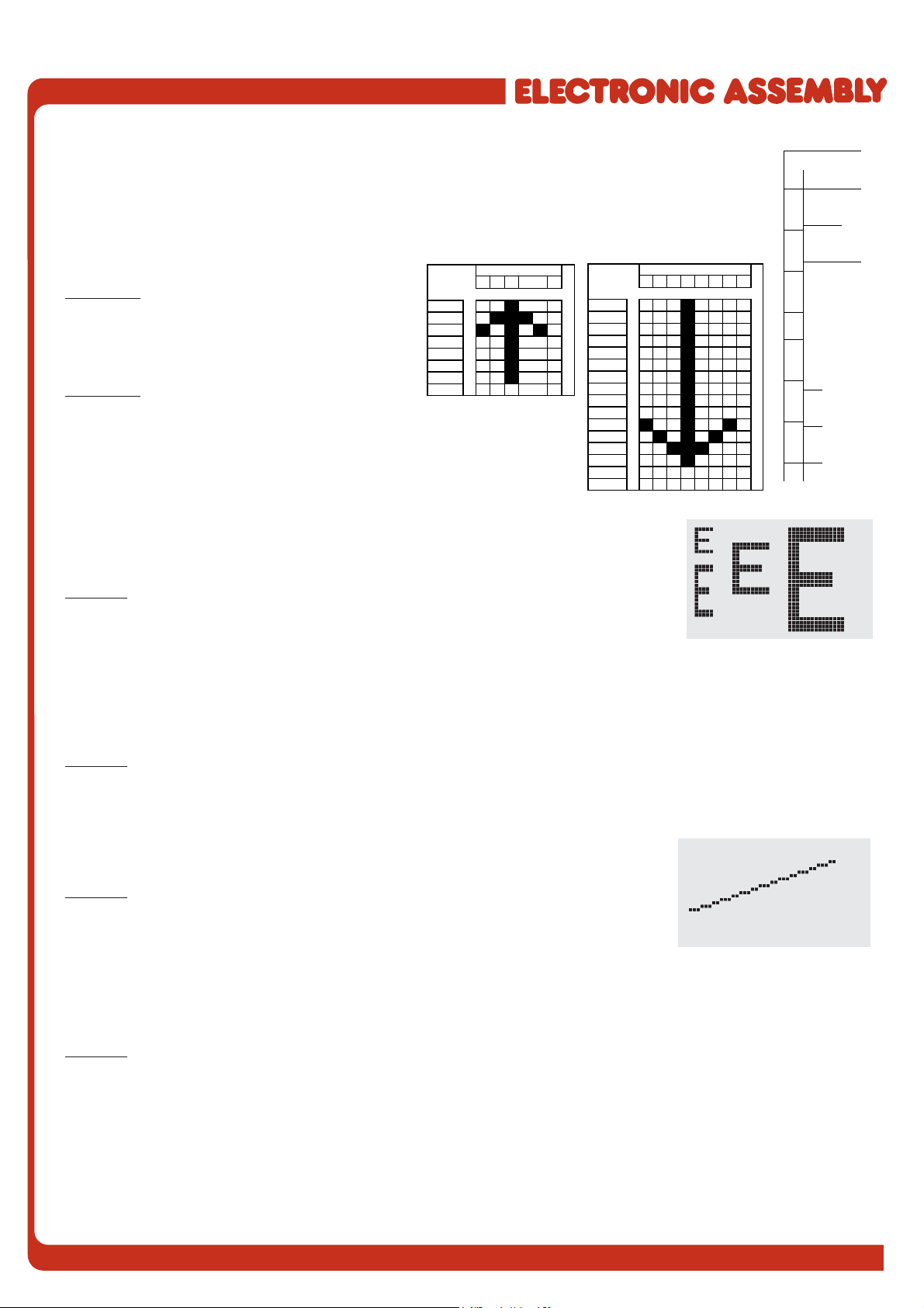
ESC E n1 data Define character
You can define up to 21 characters yourself (depending on the font size). These characters then
have the ASCII codes 1 to max. 21 and remain in an invisible screen RAM 128 bytes in size until the
supply voltage is switched off. In the case of a 4x6 font, up to 21 characters can be defined, whereas
only 8 characters can be defined for an 8x16 font. Please note that if you want to define several
characters in different fonts, you must bear in mind that a character with code 1 of the 8x16 font, for
example, requires the same amount of RAM as the characters with the codes 1 to 3 in the 4x6 font
(see the adjacent table).
Example 1:
$1B $45 $01
$04 $0E $15 $04 $04 $04 $04 $00
Defines an arrow pointing upward for ASCII no. 1
using the 6x8 character set.
Example 2:
$1B $45 $02
$08 $08 $08 $08 $08 $08 $08 $08 $08 $08 $49 $2A $1C $08 $00 $00
Defines an arrow pointing downward for ASCII no. 2 using the 8x16
character set.
ESC F n1 n2 n3 Set font
Sets the font with the number n1 (1=4x6 uppercase letters only; 2=6x8; 3=8x16). In
addition, an enlargement factor (1..8 times) is set for the width (n2) and height (n3)
separately.
Example: $1B $46 $02 $03 $04
The 6x8 with 3 times the width and 4 times the height is set with immediate effect.
In the adjacent figure, the character 'E' is shown in the 6x8 font and with various
enlargement factors.
ESC F T n1 Set terminal font
Sets the font with the number n1 for terminal operation. The font for the terminal is always used without zoom and
in REPLACE mode.
Example: $1B $46 $54 $03
The 6x8 font is set as the terminal font with immediate effect.
ESC G x1 y1 x2 y2 Draw straight line
A straight line is drawn from x1,y1 to x2,y2 taking into account the graphics mode
set 'V' (set/delete/inverse).
Example: $1B $47 $03 $14 $28 $06
A straight line is drawn from 3,20 to 50,6.
ESC H x1 y1 x2 y2 Create hard copy of display contents
Requests the area from the upper left corner (x1,y1) to the lower right corner (x2,y2). The graphics chip then
immediately sends the width and height of the image section followed by the image data. See the upload image
command ('U') for the structure of the image data.
Example: $1B $48 $00 $00 $1F $0F
The upper left part of the screen (32 x 16 pixels) is sent via RS-232.
13
EA KIT160-6
ESC J n1 Switch tone on/off manually
Switches the tone off (n1=0), on for an undefined period (n1=1) or on for n1/10 seconds (n1=2..255). (This only
applies to versions with EA KIT160-6LEDTP touch panel.)
Example: $1B $4A $0A
The tone sounds for 1 second after this command.
ESC K A add Assign address
Assigns an address to the EA KIT160 (add=0..254). The best place for this command is in the power-on macro.
Example: $1B $4B $41 $01
The EA KIT160 is assigned the address $01 with immediate effect.
ESC K S/Dadd (De)select KIT160
Selects (S) or deselects (D) the EA KIT160 with the address add (0..254); the address 255=$FF is a master
address for all EA KIT160 units.
Example: $1B $4B $44 $01
All commands for the EA KIT160 with the address $01 are ignored with immediate effect.
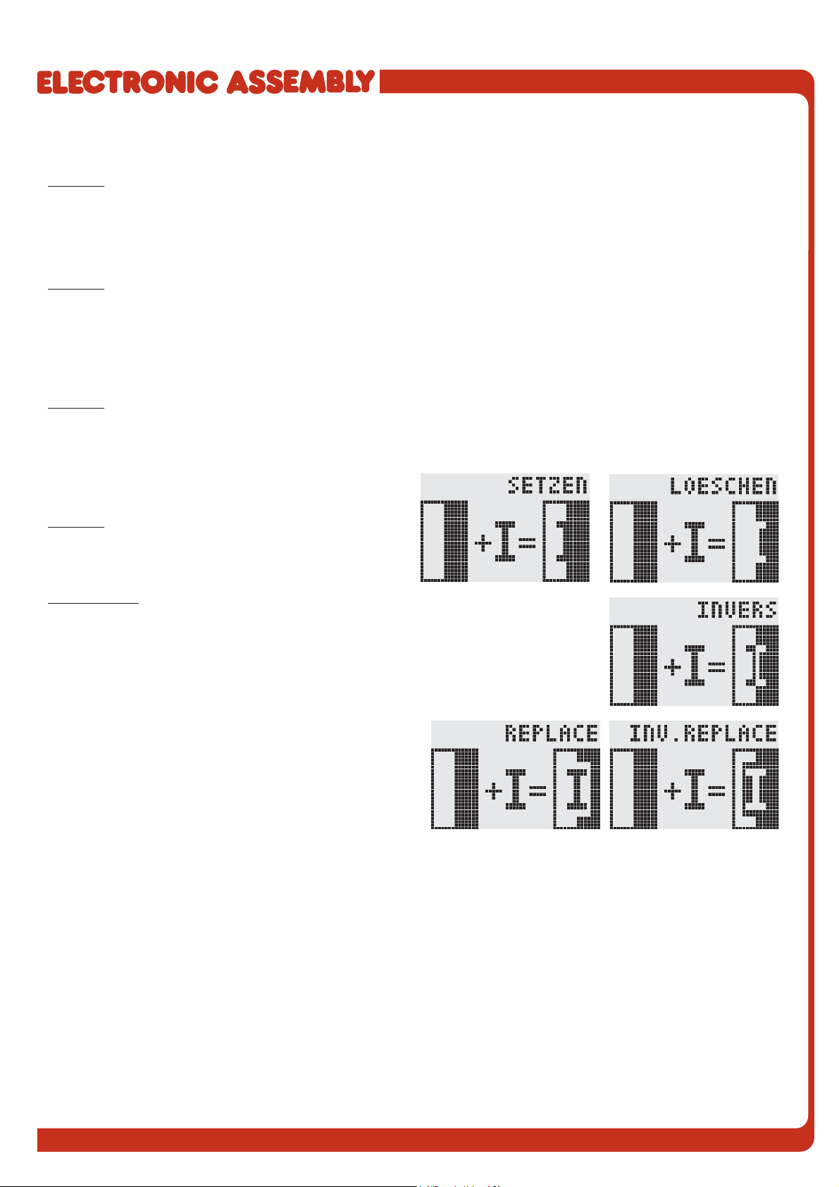
ESC L n1 pat Set text mode
Sets the link mode (n1) and pattern (pat) for the string
output text function (ESC Z).
Example: $1B $4C $03 $03
Sets the link mode for all subsequent text functions to
gray characters (pattern 3 = 50% gray) inverted with the
background.
Link mode n1:
1 = set: black pixels irrespective of the previous value (OR)
2 = delete: white pixels irrespective of the previous value
3 = inverse: changes black pixels to white pixels and vice versa (EXOR)
4 = replace: deletes the background and sets black pixels
5 = inverse replace: fills the background and sets white pixels

14
EA KIT160-6
ESC M N/T/P n1 Call macro
Calls the normal macro (N), touch macro (T) or port macro (P) with the number n1 (0..255).
Example: $1B $4D $4E $0F
The (normal) macro with the number 15 is executed.
ESC M A/J n1 n2 n3 Execute macros automatically
Calls the normal macros with the numbers n1 to n2 automatically every n3/10 seconds. A=cyclical call (e.g.
1,2,3,4,1,2,3,4, etc.);J=ping-pong call (e.g. 1,2,3,4,3,2,1,2,3,4, etc.).
Automatic execution is terminated: - When a character is received from the RS-232 interface
- When a touch automatically executes a touch macro
- When an input change executes a port macro
Example: $1B $4D $41 $01 $03 $05
The macros with the numbers 1, 2 and 3 are executed automatically with a break of 1/2 second.
ESC N H/Vx1 y1 no Text... NUL Display menu
Defines and displays a menu with the current font. The background of the menu box is
automatically saved on the clipboard (the previous contents of the clipboard are
lost):H=horizontal menu atx1,y1(upper left corner) orV=vertical menu (rotated 90°)
at x1,y1 (upper right corner). n1=currently inverted item; Text...=string containing the
items. The individual items are separated by the character '|' (=$7C). The string must
be terminated withNUL= $00.
Example 1 - Horizontal menu:
$1B $4E $48 $02 $02 $01
$54 $65 $73 $74 $7C $53 $74 $6F $70 $7C $45 $6E $64 $00
Defines a horizontal menu containing the items "Test", "Stop" and "End" at position
2,2. The 1st item is inverted.
Example 2 - Vertical menu:
$1B $4E $56 $28 $01 $01
$54 $65 $73 $74 $7C $53 $74 $6F $70 $7C $45 $6E $64 $00
Defines a vertical menu containing the items "Test", "Stop" and "End" at position 40,1.
The 1st item is inverted.
ESC N N/P Next/previous menu item
Inverts the next (N) or previous (P) menu item. If the last/first item is already inverted, the command is ignored.
Example: $1B $4E $4E
The next menu item is inverted.
ESC N I Invert menu box
Inverts the entire menu box.
Example: $1B $4E $49
ESC N S Terminate and send menu
Removes the menu from the display and restores the background. The currently selected item is sent as a number
(1..max. item) via the RS 232 interface.
Example: $1B $4E $53
ESC N M n1 Terminate menu and call macro
Removes the menu from the display and restores the background. If item 1 is selected, the (normal) macro with
the number n1 is called, for item 2 the macro n1+1 etc.
Example: $1B $4E $4D $0A
ESC N A Cancel menu
Removes the menu from the display and restores the background.
Example: $1B $4E $41

15
EA KIT160-6
ESC O n1 n2 Position cursor
Sets the cursor to column n1 and row n2 for terminal operation. The origin in the upper left corner is 1,1.
Example: $1B $4F $03 $05
Sets the cursor to the 3rd column in row 5.
ESC P x1 y1 Set dot
Sets a pixel at x1,y1 taking into account the graphics set mode 'ESC V' (set/delete/
invert).
Example: $50 $11 $0D
Sets the pixel at 17,13.
ESC Q C n1 Cursor on/off
n1=1: Switches the cursor on; it flashes at the current position on the terminal.
n1=0: Switches the cursor off.
Example: $1B $51 $43 $01
Switches the cursor off.
ESC Q D x1 y1 x2 y2 Define flashing area
Defines the area from the upper left corner (x1,y1) to the lower right corner (x2,y2) as an automatically flashing
area. The flashing function is started at the same time. This deactivates the terminal cursor.
Example: $1B $51 $44 $00 $0F $07 $10
Defines the flashing area from 0,15 to 7,16.
ESC Q Z n1 Set flashing time
Sets the flashing time to n1 (=1..15) tenths of a second. When n1= 0, the flashing function is deactivated and the
original screen restored.
Example: $1B $51 $5A $03
Sets the flashing time to 0.3 seconds.
ESC R R x1 y1 x2 y2 Draw rectangle
Draws a rectangle from the upper left corner (x1,y1) to the lower right corner (x2,y2)
taking into account the set graphics mode 'V' (set/delete/inverse). The contents of the
rectangle are not changed. See 'ESC R O' (Draw box).
Example: $1B $52 $52 $15 $08 $30 $25
Draws a rectangle from 21,8 to 48,37.

16
EA KIT160-6
ESC R N x1 y1 x2 y2 Draw rounded rectangle
Draws a rectangle with rounded corners from the upper left corner (x1,y1) to the lower
right corner (x2,y2) taking into account the set graphics mode 'V' (set/delete/inverse).
The contents of the rounded rectangle are not changed. See 'ESC R J' (Rounded box).
Example: $1B $52 $4E $06 $02 $26 $13
Draws a rounded rectangle from 6,2 to 38,19.
ESC R L x1 y1 x2 y2 Delete area
Deletes the area from the upper left corner (x1,y1) to the lower right corner (x2,y2).
Example: $1B $44 $53 $1B $52 $4C $06 $04 $28 $19
The display is filled with ESC D S and then deleted from 6,4 to 40,25.
ESC R I x1 y1 x2 y2 Invert area
Inverts the area from the upper left corner (x1,y1) to the lower right corner (x2,y2)
(black pixels turn white and vice versa).
Example: $1B $52 $49 $00 $00 $17 $1B
Inverts the area from 0,0 to 23,27 with the display contents from the "Set font"
example.
ESC R S x1 y1 x2 y2 Fill area
Fills the area from the upper left corner (x1,y1) to the lower right corner (x2,y2) (sets
the pixels to black).
Example: $1B $52 $53 $09 $05 $16 $16
Sets the area from 9,5 to 22,22 black.
ESC R M x1 y1 x2 y2 pat Fill area with pattern
Fills a rectangular area from the upper left corner (x1,y1) to the lower right corner
(x2,y2) with the pattern pat taking into account the set graphics mode "ESC V' (set/
delete/invert/replace/inverse replace).
Example: $1B $52 $4D $05 $01 $2D $1A $07
Fills the area with the pattern 7=45°cross from 5,1 to 45,26.
ESC R O x1 y1 x2 y2 pat Draw box
Draws a rectangle from the upper left corner (x1,y1) to the lower right corner (x2,y2)
with the pattern pat. The background of the box is deleted. See 'ESC R R' (Draw
rectangle).
Example: $1B $52 $4F $02 $05 $12 $1E $02
Draws a box from 2,5 to 18,30 with the pattern 2=25%gray.
ESC R J x1 y1 x2 y2 pat Draw rounded box
Draws a rectangle with rounded corners from the upper left corner (x1,y1) to the lower
right corner (x2,y2) with the pattern pat. The background is deleted. See 'ESC R N'
(Draw rounded rectangle).
Example: $1B $52 $4A $07 $03 $23 $16 $03
Draws a rounded box from 7,3 to 35,22 with the pattern 3=50%gray.
ESC S num data... Send bytes via RS-232
Outputs the next num (1..255, 0=256) bytes at the serial interface.
Example: $1B $53 $04 $54 $45 $53 $54
Transmits the word 'TEST' via the RS-232C interface.

17
EA KIT160-6
ESC T H/Vf1 f2 ret frm text... NUL Define touch key
Defines a touch key and labels it with the current font.H=horizontal or V=vertical labeling (rotated 90°). Several
touch fields can be grouped together to form a single touch key (f1=upper left touch field; f2=lower right touch field
of the new touch key). This touch key is assigned a return code with ret (1..255). When the touch key is touched,
the touch macro with the number ret is called or, if no touch macro is defined, this return code is sent via the
RS232. You use frm to define the format of the touch key (frm=0: don't draw anything;
frm=1: delete touch key; frm=2: delete touch key and draw with frame). text...=string
with the label (which is always centered on the touch key). The label can also have
more than one line; in this case, the lines are separated by the character '|' (=$7C).
The string must be concluded with NUL= $00. See example on page 3.
Example 1: Horizontal touch key:
$1B $54 $48 $01 $01 $41 $02 $54 $45 $53 $54 $00
Defines a horizontal touch key (field no. 1 only) with the return code 65='A'. The touch
key is drawn with a frame and labeled with the word 'TEST'.
Example 2: Vertical touch key:
$1B $54 $56 $02 $02 $42 $02 $54 $45 $53 $54 $00
Defines a vertical touch key (touch field no. 2 only) with the return code 66='B'. The
touch key is drawn with a frame and labeled with the word 'TEST'.
ESC T P/R Preset/reset touch fields
Assigns P (=ascending return code: 1..32) or R(=reset all touch fields) to all 32 touch fields. In the latter case all
touch fields receive the return code 0 (i.e. they are deactivated).
Example: $1B $54 $52
All touch fields are deactivated by this command and no longer recognized.
ESC T I/S n1 Touch key response
These commands set the automatic response of the touch panel to touching. Both responses can be activated
simultaneously.
I=automatic inversion when the touch key is touched (n1=0: off or n1=1: on)
S=automatic signal tone when the touch key is touched (n1=0: off or n1=1: on)
Example: $1B $54 $49 $01
After this command the tone sounds when a touch key is touched.
ESC T M ret Invert touch key manually
This command manually inverts the touch key with the return code ret.
Example: $1B $54 $4D $41
Inverts the touch key from the above example with the return code 65='A'.
ESC T A n1 (Touch) key query on/off
This command sets the (touch) key query:
n1=0: Switches the key query off - no touch macros or manual key query possible.
n1=1: Activates the key query - keystrokes trigger touch macros or are sent via RS232.
n1=2: Activates the key query - keystrokes trigger touch macros; must be queried manually.
Example: $1B $54 $41 $02
Activates the (touch) key query. The keystrokes are not sent automatically via RS232; they have to be requested
manually by means of the command ESC T W.
ESC T W Query touch key manually
Sends the return code of the currently depressed touch key at the RS232.
Example: $1B $54 $57

18
EA KIT160-6
Bit Nr. Bit Nr.
012345670123
Byte 1 Byte 2
Byte 3 Byte 4
Byte 5 Byte 6
Byte 7 Byte 8
Byte 9 Byte 10
Byte 11 Byte 12
Byte 13 Byte 14
Byte 15 Byte 16
Byte 17 Byte 18
Byte 19 Byte 20
Byte 21 Byte 22
Byte 23 Byte 24
ESC U E x1 y1 n1 Load image from EEPROM
Displays the image saved in the EEPROM with the number n1 (0..255) at position x1,y1.
Example: $1B $55 $45 $02 $03 $0E Displays image number 14 from the EEPROM at position 2,3.
ESC U L x1 y1 data... Upload image
Displays an image at position x1,y1.
data..: - 1 byte for the image width in pixels
- 1 byte for the image height in pixels
- Image data: number = ((width+7) / 8) * height bytes.
1 byte stands for 8 horizontal pixels on the screen; 0=white, 1=black;
LSB: left, MSB: right; the image is stored from the top down.
The BMP2BLH.EXE -m program on the EA DISK240 floppy disk available
as an accessory creates the image data, including the width and height,
from monochrome Windows bitmap graphics (*.BMP).
Example:
$1B $55 $4C $09 $04 $0C $0C
$F0 $00 $FC $03 $FE $07 $6E $07 $FF $0F $FF $0F
$9F $0F $FF $0F $F6 $06 $0E $07 $FC $03 $F0 $00
Loads the adjacent image at position 9,4.
ESC V n1 Set graphics mode
Sets the link mode n1 for the following graphics functions: ESC P (Set point), ESC G (straight line), ESC W
(Continue straight line), ESC R R (rectangle), ESC R N
(rounded rectangle), ESC R M (Fill area with pattern).
Example: $1B $56 $03
Sets the link mode to inverse.
By way of example, a rectangle is drawn alongside with
the link modes set, delete and inverse on an existing
background.
Link mode n1:
1 = set: black pixels irrespective of the previous value (OR)
2 = delete: white pixels irrespective of the previous value
3 = inverse: changes black pixels to white pixels and vice versa (EXOR)
4 = replace: deletes the background and sets black pixels; only area with fill pattern
5 = inverse replace: fills background and sets white pixels; only area with fill pattern
ESC W x1 y1 Continue straight line
Continues a straight line from the last end or point drawn to x1,y1 taking into account
the set graphics mode 'V'.
Example:
$1B $47 $00 $00 $10 $04
$1B $57 $16 $1B
$1B $57 $30 $0F
A straight line is drawn from 0,0 to 16,4.It is then continued to 22,27 and to 48,15.
ESC X n1 Wait/pause
This command suspends the EA KIT160 for n1/10 seconds.
Example: $1B $58 $0A
After this command the EA KIT160 waits for a second before the next command is processed.
ESC Y R n1 Read input port
Reads in the input port (n1=1..8 = IN1..IN8). When n1=0, all the inputs are read in as 8-bit binary values
(MSB:IN8...In1:LSB); see application on page 5. The command "ESC Y I 1" puts this right (input open: 0).
Example: $1B $59 $52 $03
Reads in port IN3. The result is sent via RS232.

19
EA KIT160-6
ESC Y W n1 n2 Write output port
Changes the output port (n1=1..8 = OUT1..OUT8) to the valuen2 (0=low level; 1=high level; 2=invert port). When
n1=0, all the outputs are output as a binary value n2 (MSB:OUT8...OUT1:LSB); see application on page 5.
Example: $1B $59 $57 $02 $01
Switches the output port OUT2 to high level.
ESC Y A n1 Automatic port query on/off
Each change at the input port (8-bit binary value IN8..IN1) can call a port macro (0..255). This command activates
(n1=1) or deactivates (n1=0) the automatic port query. After power-on, the current port status is read and the
associated port macro executed immediately.
Example: $1B $59 $41 $01
Activates the automatic port query and executes the associated port macro.
ESC Y I n1 Invert input port
This command allows the logic of the input port to be inverted (n1=0 for normal or n1=1 for inverse). This is useful
with the optocoupler inputs, for example.
Example: $1B $59 $49 $01
Inverts the input port logic.
ESC Y L n1 LED backlight On/Off
LED backlight is switched off (n1=0) or permanently on (n1=1). Atn1=2 backlight is inverted (on->off, off->on).
n1=3..255 turns the backlight n1/10 sec. on and then off. Note: LED backlight is the same line as output port 8. If
you need to use output port 8 then you have to cut backlight from output 8 by changing the solder strip LB8.
Backlight will be turned on and cannot controled by software anymore.
ESC Z L/Z/R x1 y1 text... NUL Horizontal string
Writes the string text... left justified (L), centered (Z) or right justified (R) at position
x1 taking into account the set text mode (ESC L). Multi-line text can also be output,
with the lines separated by the character '|' (=$7C). The string must be concluded with
NUL= $00. Position y1 is the upper edge of the 1st line.
Example 1: Writes the text "Left|Ok" left justified at 0,0.
$1B $5A $4C $00 $00 $4C $65 $66 $74 $7C $4F $6B $00
Example 2: Writes the text "Center|Ok" centered at 25,0.
$1B $5A $5A $19 $00 $43 $65 $6E $74 $65 $72 $7C $4F
$6B $00
Example 3: Writes the text "Right|Ok" right justified at 49,0.
$1B $5A $52 $31 $00 $52 $69 $67 $68 $74 $7C $4F $6B
$00
ESC Z O/M/U x1 y1 text... NUL Vertical string
Writes the string text... rotated by 90° degrees top justified (O), vertically centered (M)
or bottom justified (U) at position y1 taking into account the text mode (ESC L). Multi-
line text can also be output, with the lines separated by the character '|' (=$7C). The
string must be concluded with NUL= $00. Position x1 is the right edge of the 1st line.
Example 1: Writes the text "Top|Ok" top justified at 49,0.
$1B $5A $4F $31 $00 $54 $6F $70 $7C $4F $6B $00
Example 2: Writes the text "Mid|Ok" vertically centered at
49,15.
$1B $5A $4D $31 $0F $4D $69 $64 $7C $4F $6B $00
Example 3: Writes the text "Bot|Ok" bottom justified at
49,31.
$1B $5A $55 $31 $1F $42 $6F $74 $7C $4F $6B $00

EA KIT160-6
ZEPPELINSTRASSE 19
·
D- 82205 GILCHING
TEL 08105/778090
·
FAX 08105/778099
·
http://www.lcd-module.de
DIMENSIONS
all dimensions are in mm
panel cutout 97,5x75,0 mm
antireflex screen or
Touch Panel
ATTENTION
handling precautions!
HINTS FOR HANDLING AND OPERATING
- The module can be destroyed electrically by mispoled or overvoltaged power supply, wrong polarity,
overvoltage or static discharge on inputs or shortened outputs.
- Before disassembling the module, the power supply must be switched off. Also all inputs must not carry
anycurrent.
- Display, touch screen and cover glass are scratch- sensitive plastic materials and should not be
touched with hard objects.
- Surfaces should be cleaned with soft fabric without using of chemical solvents.
- The module is designed for indoor use only. For operating in outside
enviroment adequate precautions must be undertaken. Maximum operating
temperature range from 0..+50°C should be not exceeded. In humid
atmosphere or in condensing situations the module functions may drop out.
Direct sun exposure to the display should be avoided. Storage temperature
range is -20..+70°C.
This manual suits for next models
5
Table of contents
Other ELECTRONIC ASSEMBLY Control Panel manuals

Popular Control Panel manuals by other brands

Spa-Quip
Spa-Quip Spa Power 750 Quick Card User Guide

CAME
CAME Z 24 Series installation manual

BFT
BFT LEO B CBB 3 230 L02 installation manual

See Water
See Water OSSIM-TP-100 Series Installation and operation manual

Feelsafe
Feelsafe OMNI 3000 Hook-up & Installation

Extron electronics
Extron electronics SCP 100P user manual


