Electronics International Inc EDC-33 Series User manual
Engine Data ConverterEngine Data Converter
Engine Data ConverterEngine Data Converter
Engine Data Converter
EDC-33( )EDC-33( )
EDC-33( )EDC-33( )
EDC-33( )
Operating and Installation InstructionsOperating and Installation Instructions
Operating and Installation InstructionsOperating and Installation Instructions
Operating and Installation Instructions
II 0503161
Electronics International Inc.Electronics International Inc.
Electronics International Inc.Electronics International Inc.
Electronics International Inc. ®®
®®
®
Rev A: 3/1/17 **
63296 Powell Butte Hwy • Bend, OR 97701 • (541) 318-6060 • Buy-EI.com63296 Powell Butte Hwy • Bend, OR 97701 • (541) 318-6060 • Buy-EI.com
63296 Powell Butte Hwy • Bend, OR 97701 • (541) 318-6060 • Buy-EI.com63296 Powell Butte Hwy • Bend, OR 97701 • (541) 318-6060 • Buy-EI.com
63296 Powell Butte Hwy • Bend, OR 97701 • (541) 318-6060 • Buy-EI.com
Part #:Part #:
Part #:Part #:
Part #:
S/N:S/N:
S/N:S/N:
S/N:
You must read this manual before installing or operating the instrument. This
manual contains warranty and other information that may affect your decision
to install this product and/or the safety of your aircraft.

Important Notice
***** MUST READ *****
Page 1 of 4
If you think it is not important to read this manual, you're wrong!If you think it is not important to read this manual, you're wrong!
If you think it is not important to read this manual, you're wrong!If you think it is not important to read this manual, you're wrong!
If you think it is not important to read this manual, you're wrong! This manual contains impor-
tant operating information that may affect the safety of the pilot, passengers, aircraft, operation of the
system or time to install the system. You MUST read the manual prior to installing this system. Any
deviation from these installation instructions is the sole responsibility of the installer and should be done
in accordance with AC 43.13.
Read the Warranty/AgreementRead the Warranty/Agreement
Read the Warranty/AgreementRead the Warranty/Agreement
Read the Warranty/Agreement. There is information in the Warranty/Agreement that may alter your
decision to install this product. If you do not accept the terms of the Warranty/Agreement, doIf you do not accept the terms of the Warranty/Agreement, do
If you do not accept the terms of the Warranty/Agreement, doIf you do not accept the terms of the Warranty/Agreement, do
If you do not accept the terms of the Warranty/Agreement, do
not install this productnot install this product
not install this productnot install this product
not install this product. This product may be returned for a refund. Contact Electronics International
Inc. for details.
If you are not an FAA Certified Aircraft Mechanic familiar with the issues of installingIf you are not an FAA Certified Aircraft Mechanic familiar with the issues of installing
If you are not an FAA Certified Aircraft Mechanic familiar with the issues of installingIf you are not an FAA Certified Aircraft Mechanic familiar with the issues of installing
If you are not an FAA Certified Aircraft Mechanic familiar with the issues of installing
aircraft instruments,aircraft instruments,
aircraft instruments,aircraft instruments,
aircraft instruments, Do Not attempt to install this unit.Do Not attempt to install this unit.
Do Not attempt to install this unit.Do Not attempt to install this unit.
Do Not attempt to install this unit. The installer should use currentThe installer should use current
The installer should use currentThe installer should use current
The installer should use current
aircraft standards and practices to install this system (refer to AC 43.13).aircraft standards and practices to install this system (refer to AC 43.13).
aircraft standards and practices to install this system (refer to AC 43.13).aircraft standards and practices to install this system (refer to AC 43.13).
aircraft standards and practices to install this system (refer to AC 43.13).
If the installer does not have the skills, knowledge, tools, equipment or facility, to perform and determine
whether the installation of this product is safe, reliable and accurate and to determine whether this product
is operating properly after installation, DO NOT INSTALL THIS PRODUCTDO NOT INSTALL THIS PRODUCT
DO NOT INSTALL THIS PRODUCTDO NOT INSTALL THIS PRODUCT
DO NOT INSTALL THIS PRODUCT. If the owner/pilot and/
or installer are unwilling to take the responsibility for the installation and operation of this product, DODO
DODO
DO
NOT INSTALL THIS PRODUCT.NOT INSTALL THIS PRODUCT.
NOT INSTALL THIS PRODUCT.NOT INSTALL THIS PRODUCT.
NOT INSTALL THIS PRODUCT. This product may be returned for a refund. Contact Electronics
International Inc. for details.
By installing this product, the aircraft owner/pilot and installer agree to hold Electronics International Inc.
harmless and in no way responsible for monetary compensation, including punitive damages for any
incident, harm and/or damage associated with this product. If you do not agree to the above, DO NOTDO NOT
DO NOTDO NOT
DO NOT
INSTALL THIS PRODUCT.INSTALL THIS PRODUCT.
INSTALL THIS PRODUCT.INSTALL THIS PRODUCT.
INSTALL THIS PRODUCT. This product may be returned for a refund. Contact Electronics Interna-
tional Inc. for details.
Electronics International Inc. is not liable or responsible for a pilot’s action or any situation that results in
personal injury, property damage, missed commitments, lack of use of an aircraft or any expenses in-
curred due to: product failure, inaccuracy in displayed data or text files, display or display format issues,
software bugs or problems, upgrade or customization issues, misinterpretation of the display, warning
and/or limit settings, calibration problems, installation issues (leaks, mis-wiring, obstructions, damage to
aircraft or components, incorrect installation of any parts, wrong parts, parts that don’t fit, etc.) or any
other issues related to the installation or operation of this product. All of the above are solely the pilot’s
and/or installer’s responsibility. The pilot mustmust
mustmust
must understand the operation of this product before flying the
aircraft. The pilot must not allow anyone to operate the aircraft that does not know the operation of this
product. If you do not agree to the above, DO NOT INSTALL THIS PRODUCT.DO NOT INSTALL THIS PRODUCT.
DO NOT INSTALL THIS PRODUCT.DO NOT INSTALL THIS PRODUCT.
DO NOT INSTALL THIS PRODUCT. This product may
be returned for a refund. Contact Electronics International Inc. for details.
Before starting the installation make sure the unit will fit in the location you intend to install it without
obstructing the operation of any controls.

Important Notice
***** MUST READ *****
Page 2 of 4
If the EDC is configured to monitor the aircrafts fuel tanks, the EDC must be calibrated to the aircraft
fuel system and the EDC's accuracy must be verified before flying the aircraft.
The accuracy and proper operation of each function monitored on the EDC should be verified before
the aircraft is released for flight.
When the installation is finished, inspect the system for loose fittings, connections, clamps, probes and
inspect for leaks, chafing, obstructions, heat damage and anything that may cause unsafe flight before
the 1st run-up, after the 1st run-up and after the first flight.
FuelLevelAccuracyLimitations:
The accuracy limitations of the EDC are listed below. It is the pilot/owner’s obligation to makeIt is the pilot/owner’s obligation to make
It is the pilot/owner’s obligation to makeIt is the pilot/owner’s obligation to make
It is the pilot/owner’s obligation to make
anyone flying the aircraft aware of these limitations.anyone flying the aircraft aware of these limitations.
anyone flying the aircraft aware of these limitations.anyone flying the aircraft aware of these limitations.
anyone flying the aircraft aware of these limitations.
1. Angle of Attack -1. Angle of Attack -
1. Angle of Attack -1. Angle of Attack -
1. Angle of Attack - The EDC must be calibrated with the aircraft in a cruise angle of attack. If the
aircraft is in an angle of attack other than cruise, the EDC may display inaccurate fuel levels (depend-
ing on the mounting location and type of sensor used). If your aircraft does not sit at a cruise angle of
attack when on the ground, it may not display accurate fuel levels. Test your aircraft at differentTest your aircraft at different
Test your aircraft at differentTest your aircraft at different
Test your aircraft at different
angles of attack to see the affects on the EDC fuel level readings.angles of attack to see the affects on the EDC fuel level readings.
angles of attack to see the affects on the EDC fuel level readings.angles of attack to see the affects on the EDC fuel level readings.
angles of attack to see the affects on the EDC fuel level readings.
2. Full Fuel Readings -Full Fuel Readings -
Full Fuel Readings -Full Fuel Readings -
Full Fuel Readings - As a tank is filled the fuel sensor may not be able to detect the fuel entering
the upper corners of the fuel tank. If this is the case with your sensor, the EDC will display lower fuel
levels than the actual fuel in the tanks when the tanks are full. When the fuel level drops to a point
where the fuel sensor starts to detect a change, the displayed fuel level should be accurate. Check theCheck the
Check theCheck the
Check the
accuracy of your system by comparing the transmited fuel levels from the EDC to theaccuracy of your system by comparing the transmited fuel levels from the EDC to the
accuracy of your system by comparing the transmited fuel levels from the EDC to theaccuracy of your system by comparing the transmited fuel levels from the EDC to the
accuracy of your system by comparing the transmited fuel levels from the EDC to the
fuel levels listed in the flight manual at each fill up.fuel levels listed in the flight manual at each fill up.
fuel levels listed in the flight manual at each fill up.fuel levels listed in the flight manual at each fill up.
fuel levels listed in the flight manual at each fill up.
3. Low Fuel Readings -3. Low Fuel Readings -
3. Low Fuel Readings -3. Low Fuel Readings -
3. Low Fuel Readings - Do not rely on the EDC to determine the fuel level in the tankDo not rely on the EDC to determine the fuel level in the tank
Do not rely on the EDC to determine the fuel level in the tankDo not rely on the EDC to determine the fuel level in the tank
Do not rely on the EDC to determine the fuel level in the tank
for an indicated tank level below 1/8for an indicated tank level below 1/8
for an indicated tank level below 1/8for an indicated tank level below 1/8
for an indicated tank level below 1/8..
..
. You should always fly the aircraft in such a manner as to
maintain at least the FAA minimum fuel requirements in the aircraft at all times.
4. Improper Calibration -4. Improper Calibration -
4. Improper Calibration -4. Improper Calibration -
4. Improper Calibration - If the EDC has not been properly calibrated it will not transmit accurate
fuel levels in the tanks. It is important you verify the accuracy of the EDC. Always crosscheckAlways crosscheck
Always crosscheckAlways crosscheck
Always crosscheck
your measured fuel levels in the tanks with the transmited levels from the EDC beforeyour measured fuel levels in the tanks with the transmited levels from the EDC before
your measured fuel levels in the tanks with the transmited levels from the EDC beforeyour measured fuel levels in the tanks with the transmited levels from the EDC before
your measured fuel levels in the tanks with the transmited levels from the EDC before
each flight.each flight.
each flight.each flight.
each flight.
5. Poor Connections -5. Poor Connections -
5. Poor Connections -5. Poor Connections -
5. Poor Connections - Poor connections between the wires leading from the EDC to the fuel
sensors can become intermittent. An intermittent connection most likely will show up as wandering or
inaccurate readings. Always crosscheck your measured fuel levels in the tanks with theAlways crosscheck your measured fuel levels in the tanks with the
Always crosscheck your measured fuel levels in the tanks with theAlways crosscheck your measured fuel levels in the tanks with the
Always crosscheck your measured fuel levels in the tanks with the
readings transmitted from the EDC before each flight.readings transmitted from the EDC before each flight.
readings transmitted from the EDC before each flight.readings transmitted from the EDC before each flight.
readings transmitted from the EDC before each flight.

Important Notice
***** MUST READ *****
Page 3 of 4
6. Defective Fuel Level Sensors -6. Defective Fuel Level Sensors -
6. Defective Fuel Level Sensors -6. Defective Fuel Level Sensors -
6. Defective Fuel Level Sensors - Fuel sensors can become intermittent or change resistance
with age. It is not uncommon to find intermittent problems even in new sensors. An intermittent
problem with a fuel sensor most likely will show up as wandering or inaccurate readings. AlwaysAlways
AlwaysAlways
Always
crosscheck the measured fuel levels in the tanks with the readings transmitted from thecrosscheck the measured fuel levels in the tanks with the readings transmitted from the
crosscheck the measured fuel levels in the tanks with the readings transmitted from thecrosscheck the measured fuel levels in the tanks with the readings transmitted from the
crosscheck the measured fuel levels in the tanks with the readings transmitted from the
EDC at each fill up.EDC at each fill up.
EDC at each fill up.EDC at each fill up.
EDC at each fill up.
If you ever find an inaccuracy issue or any other problem with a fuel level display,If you ever find an inaccuracy issue or any other problem with a fuel level display,
If you ever find an inaccuracy issue or any other problem with a fuel level display,If you ever find an inaccuracy issue or any other problem with a fuel level display,
If you ever find an inaccuracy issue or any other problem with a fuel level display,
troubleshoot and fix the problem before flying the aircraft.troubleshoot and fix the problem before flying the aircraft.
troubleshoot and fix the problem before flying the aircraft.troubleshoot and fix the problem before flying the aircraft.
troubleshoot and fix the problem before flying the aircraft.
If you do not agree to all of the above, DO NOT INSTALL THIS PRODUCT.DO NOT INSTALL THIS PRODUCT.
DO NOT INSTALL THIS PRODUCT.DO NOT INSTALL THIS PRODUCT.
DO NOT INSTALL THIS PRODUCT. This product may
be returned for a refund. Contact Electronics International Inc. for details.
ImportantFuelLevelConsiderations:
DO NOT RELY SOLELY ON THE FUEL LEVEL TRANSMITTED FROM THE EDC
TO DETERMINE THE FUEL LEVELS IN THE AIRCRAFT. The use of the EDC does not
eliminate or reduce the necessity for the pilot to use good flight planning, preflight and in-flight
techniques for managing fuel. It is important the pilot adopt the practices listed below. If you are not
familiar with these techniques, contact the FAA to acquire proper training.
1. Flight Planning - Always calculate the fuel requirement for each leg of a flight, including any alternate
plans for bad weather. Keep this information available in the aircraft during the flight. Keep a chart
of the published fuel flows for various flight/engine conditions in the aircraft. Keep a chart of the
measured fuel flows for various flights in the aircraft. Measured fuel flows can be considerably
different from published figures. This usually is due to old, inaccurate engine instruments.
2. Preflight - Do not rely on the EDC to determine the fuel level in the fuel tanks. The pilot
must visually check/measure the fuel levels in the tanks before every takeoff. Crosscheck the
measured fuel levels with the displayed levels. Also, crosscheck these levels with the fuel requirements
for the flight listed in your flight plan.
3. In Flight - Make the displayed fuel level is part of your normal instrument scan. Crosscheck
the fuel levels displayed with your flight plan at each leg of the flight or every 30
minutes (whichever happens first). If there is a discrepancy, land the aircraft at the nearest
airport and verify the fuel levels. Discrepancies should be taken seriously.
4. New Pilot or Owner of the Aircraft - If there is a new pilot or owner of the aircraft, it is
the previous aircraft pilot/owner’s responsibility to insure the new pilot has read this

manual and is aware of any accuracy limitations and other important considerations.
All limitations and operating characteristics learned from operating the EDC must be
passed on to the new pilot/owner.
If you do not agree or are unwilling to comply with the information/requirements contained within this
Important Notice, DO NOT INSTALL THIS PRODUCT.DO NOT INSTALL THIS PRODUCT.
DO NOT INSTALL THIS PRODUCT.DO NOT INSTALL THIS PRODUCT.
DO NOT INSTALL THIS PRODUCT. This product may be returned for a
refund. Contact Electronics International Inc. for details.
Important Notice
***** MUST READ *****
Page 4 of 4

Contents
Warranty/Agreement------------------------------------------------------------------------- 1A
1.0 Operating Instructions ----------------------------------------------------------------- 1
1.1 System Description ----------------------------------------------------------------- 1
1.2 EDC Configurations --------------------------------------------------------------- 1
1.3 Operation ------------------------------------------------------------------------- 2
1.4 Visual Status Indicator (VSI) ------------------------------------------------------- 2
2.0 Installation Instructions ----------------------------------------------------------------- 3
2.1 Install the EDC -------------------------------------------------------------------- 3
2.2 Setup and Calibration ------------------------------------------------------------- 4
2.3 Periodic Maintenance -------------------------------------------------------------- 4
2.4 Continued Airworthiness ---------------------------------------------------------- 4
2.5 Inspection Intervals ---------------------------------------------------------------- 4
2.6 Service Life ------------------------------------------------------------------------ 4
2.7 Limitations ------------------------------------------------------------------------- 4
2.8 SAE Standards, TSOs and MPS -------------------------------------------------- 5
3.0 Sample Wiring Diagram ---------------------------------------------------------------- 11
4.0 DO-160G Environmental Qualification Form ------------------------------------------- 13
5.0 Specifications / Features ---------------------------------------------------------------- 17

1A
Warranty / Agreement
Electronics International Inc. (EI) warrants this instrument and system components to be free from defects in
materials and workmanship for a period of two years from the user invoice date. EI will repair or replace any
item under the terms of this Warranty provided the item is returned to the factory prepaid.
1. If you do not agree to and acceptIf you do not agree to and accept
If you do not agree to and acceptIf you do not agree to and accept
If you do not agree to and accept ALLALL
ALLALL
ALL the terms of this Warranty/Agreement,the terms of this Warranty/Agreement,
the terms of this Warranty/Agreement,the terms of this Warranty/Agreement,
the terms of this Warranty/Agreement, DO NOT InstallDO NOT Install
DO NOT InstallDO NOT Install
DO NOT Install
This ProductThis Product
This ProductThis Product
This Product..
..
. You may return the product for a refund, contact Electronics International Inc. for details.
2. Electronics International Inc. is not liable or responsible for a pilot’s action or any situation that results in
personal injury, property damage, missed commitments, lack of use of an aircraft or any expenses incurred due
to: product failure, inaccuracy in displayed data or text files, display or display format issues, software bugs or
problems, upgrade or customization issues, misinterpretation of the display, warning and/or limit settings,
calibration problems, installation issues (leaks, mis-wiring, obstructions, damage to aircraft or components,
incorrect installation of any parts, wrong parts, part that don’t fit, etc.) or any other issues related to the installa-
tion or operation of this product. All of the above are solely the pilot’s and/or installer’s responsibility. The
pilot mustmust
mustmust
must
understand the operation of this product before flying the aircraft. The pilot will not allow anyone
to operate the aircraft that does not know the operation of this product.
By installing this product, the aircraft owner/pilot and installer agree to hold Electronics International Inc.
harmless and in no way responsible for monetary compensation, including punitive damages for any incident,
harm and/or damage associated with this product (including but not limited to the ones listed above). If you do
not agree to any part of this Warranty/Agreement, DO NOT INSTALL THIS PRODUCT.DO NOT INSTALL THIS PRODUCT.
DO NOT INSTALL THIS PRODUCT.DO NOT INSTALL THIS PRODUCT.
DO NOT INSTALL THIS PRODUCT.
3. It is possible for any system to fail thereby displaying inaccurate high, low or jumpy readings. Therefore,
you mustmust
mustmust
must be able to recognize an system failure and you mustmust
mustmust
must be proficient in operating your aircraft safely in
spite of a system failure. If you do not have this knowledge, contact the FAA or a knowledgeable flight
instructor for training prior to flying the aircraft with this system.
4. This Warranty/Agreement shall not apply to any product that has been repaired or altered by any person
other than Electronics International Inc., or that has been subjected to misuse, accident, incorrect wiring,
negligence, improper or unprofessional assembly or improper installation by any person. This warrantyThis warranty
This warrantyThis warranty
This warranty
does not cover any reimbursement for any person’s time for installation, removal, assembly ordoes not cover any reimbursement for any person’s time for installation, removal, assembly or
does not cover any reimbursement for any person’s time for installation, removal, assembly ordoes not cover any reimbursement for any person’s time for installation, removal, assembly or
does not cover any reimbursement for any person’s time for installation, removal, assembly or
repair.repair.
repair.repair.
repair. Electronics International retains the right to solely determine the reason or cause for warranty repair.
5. This warranty does not extend to any machine, vehicle, boat, aircraft or any other device to which the
Electronics International Inc. product may be connected, attached, interconnected or used in conjunction with
in any way.
6. Personal injury or property damage due to misinterpretation or lack of understanding of this product is
solely the pilot's responsibility. The pilot mustmust
mustmust
must understand all aspects of the operation of this product before
flying the aircraft. If he/she does not, he or she agrees to seek training from a knowledgeable instructor. The
pilot also agrees that no one will be allowed to operate the aircraft that does not know the operation and limita-
tions of this product.
More On Back of this PageMore On Back of this Page
More On Back of this PageMore On Back of this Page
More On Back of this Page

7. The obligation assumed by Electronics International Inc. under this warranty is limited to repair, replace-
ment or refund of the product, at the sole discretion of Electronics International Inc.
8. Electronics International Inc. is not liable for expenses incurred by the customer or installer due to factory
updates, modifications, improvements, changes, or any other alterations to the product that may affect the
form, fit, function or operation of the product.
9. Electronics International is not responsible for shipping charges or damages incurred under this Warranty.
10. No representative is authorized to assume any other liability for Electronics International Inc. in connec-
tion with the sale of Electronics International Inc. products.
11. You must read the entire Operating and Installation Instructions for this unit. If you do notYou must read the entire Operating and Installation Instructions for this unit. If you do not
You must read the entire Operating and Installation Instructions for this unit. If you do notYou must read the entire Operating and Installation Instructions for this unit. If you do not
You must read the entire Operating and Installation Instructions for this unit. If you do not
agree to and accept the terms of this Warranty/Agreement and the responsibilities set forth inagree to and accept the terms of this Warranty/Agreement and the responsibilities set forth in
agree to and accept the terms of this Warranty/Agreement and the responsibilities set forth inagree to and accept the terms of this Warranty/Agreement and the responsibilities set forth in
agree to and accept the terms of this Warranty/Agreement and the responsibilities set forth in
these manuals, DO NOT install this product, contact E.I. for a refund.these manuals, DO NOT install this product, contact E.I. for a refund.
these manuals, DO NOT install this product, contact E.I. for a refund.these manuals, DO NOT install this product, contact E.I. for a refund.
these manuals, DO NOT install this product, contact E.I. for a refund.
This Warranty is made only to the original user. THIS WARRANTY IS IN LIEU OF ALL OTHERTHIS WARRANTY IS IN LIEU OF ALL OTHER
THIS WARRANTY IS IN LIEU OF ALL OTHERTHIS WARRANTY IS IN LIEU OF ALL OTHER
THIS WARRANTY IS IN LIEU OF ALL OTHER
WARRANTIES OR OBLIGATIONS: EXPRESS OR IMPLIED. MANUFACTURER EXPRESSLYWARRANTIES OR OBLIGATIONS: EXPRESS OR IMPLIED. MANUFACTURER EXPRESSLY
WARRANTIES OR OBLIGATIONS: EXPRESS OR IMPLIED. MANUFACTURER EXPRESSLYWARRANTIES OR OBLIGATIONS: EXPRESS OR IMPLIED. MANUFACTURER EXPRESSLY
WARRANTIES OR OBLIGATIONS: EXPRESS OR IMPLIED. MANUFACTURER EXPRESSLY
DISCLAIMS ALL IMPLIED WARRANTIES OF MERCHANTABILITY OR FITNESS FOR ADISCLAIMS ALL IMPLIED WARRANTIES OF MERCHANTABILITY OR FITNESS FOR A
DISCLAIMS ALL IMPLIED WARRANTIES OF MERCHANTABILITY OR FITNESS FOR ADISCLAIMS ALL IMPLIED WARRANTIES OF MERCHANTABILITY OR FITNESS FOR A
DISCLAIMS ALL IMPLIED WARRANTIES OF MERCHANTABILITY OR FITNESS FOR A
PARTICULAR PURPOSE. PURCHASER AGREES THAT IN NO EVENT SHALL MANUFAC-PARTICULAR PURPOSE. PURCHASER AGREES THAT IN NO EVENT SHALL MANUFAC-
PARTICULAR PURPOSE. PURCHASER AGREES THAT IN NO EVENT SHALL MANUFAC-PARTICULAR PURPOSE. PURCHASER AGREES THAT IN NO EVENT SHALL MANUFAC-
PARTICULAR PURPOSE. PURCHASER AGREES THAT IN NO EVENT SHALL MANUFAC-
TURER BE LIABLE FOR SPECIAL, INCIDENTAL OR CONSEQUENTIAL DAMAGES, IN-TURER BE LIABLE FOR SPECIAL, INCIDENTAL OR CONSEQUENTIAL DAMAGES, IN-
TURER BE LIABLE FOR SPECIAL, INCIDENTAL OR CONSEQUENTIAL DAMAGES, IN-TURER BE LIABLE FOR SPECIAL, INCIDENTAL OR CONSEQUENTIAL DAMAGES, IN-
TURER BE LIABLE FOR SPECIAL, INCIDENTAL OR CONSEQUENTIAL DAMAGES, IN-
CLUDING LOST PROFITS OR LOSS OF USE OR OTHER ECONOMIC LOSS. EXCEPT ASCLUDING LOST PROFITS OR LOSS OF USE OR OTHER ECONOMIC LOSS. EXCEPT AS
CLUDING LOST PROFITS OR LOSS OF USE OR OTHER ECONOMIC LOSS. EXCEPT ASCLUDING LOST PROFITS OR LOSS OF USE OR OTHER ECONOMIC LOSS. EXCEPT AS
CLUDING LOST PROFITS OR LOSS OF USE OR OTHER ECONOMIC LOSS. EXCEPT AS
EXPRESSLY PROVIDED HEREIN, MANUFACTURER DISCLAIMS ALL OTHER LIABILITYEXPRESSLY PROVIDED HEREIN, MANUFACTURER DISCLAIMS ALL OTHER LIABILITY
EXPRESSLY PROVIDED HEREIN, MANUFACTURER DISCLAIMS ALL OTHER LIABILITYEXPRESSLY PROVIDED HEREIN, MANUFACTURER DISCLAIMS ALL OTHER LIABILITY
EXPRESSLY PROVIDED HEREIN, MANUFACTURER DISCLAIMS ALL OTHER LIABILITY
TO PURCHASER OR ANY OTHER PERSON IN CONNECTION WITH THE USE OR PERFOR-TO PURCHASER OR ANY OTHER PERSON IN CONNECTION WITH THE USE OR PERFOR-
TO PURCHASER OR ANY OTHER PERSON IN CONNECTION WITH THE USE OR PERFOR-TO PURCHASER OR ANY OTHER PERSON IN CONNECTION WITH THE USE OR PERFOR-
TO PURCHASER OR ANY OTHER PERSON IN CONNECTION WITH THE USE OR PERFOR-
MANCE OF MANUFACTURER’S PRODUCTS, INCLUDING SPECIFICALLY LIABILITY INMANCE OF MANUFACTURER’S PRODUCTS, INCLUDING SPECIFICALLY LIABILITY IN
MANCE OF MANUFACTURER’S PRODUCTS, INCLUDING SPECIFICALLY LIABILITY INMANCE OF MANUFACTURER’S PRODUCTS, INCLUDING SPECIFICALLY LIABILITY IN
MANCE OF MANUFACTURER’S PRODUCTS, INCLUDING SPECIFICALLY LIABILITY IN
TORT.TORT.
TORT.TORT.
TORT.
1B

1.0 Operating Instructions
1.1 System Description:
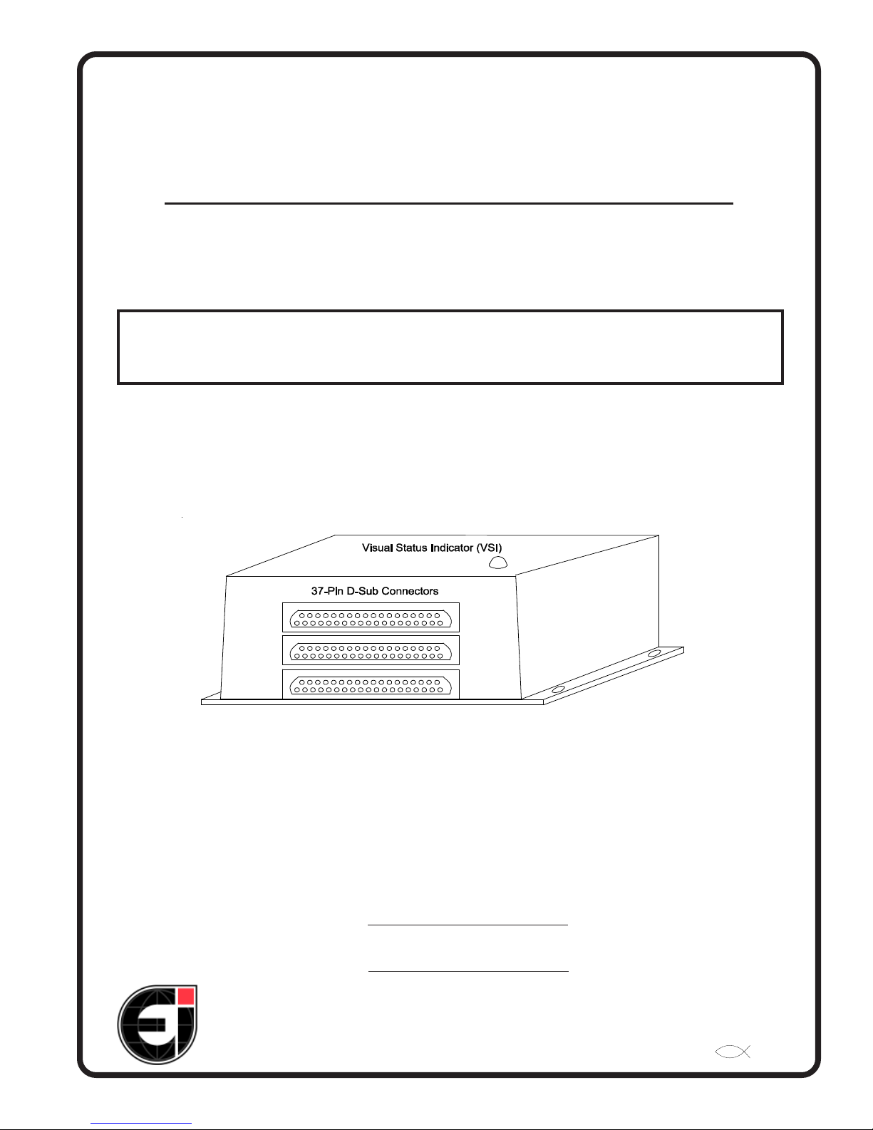
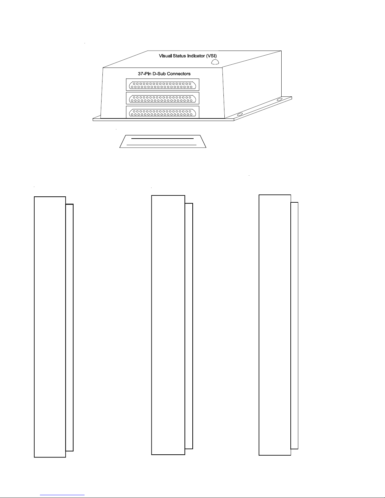
The EDC-33xx-( ) (called EDC) is a 4.6" x 3.6" x 2.2" box with three 37-pin D-Sub connectors on the front.
Engine and aircraft functions are measured (via sensor, probes, transducers, etc.), processed and transmitted on
a serial output port. The output data can then be used by another instrument to display primary engine and
aircraft information to the pilot or it can be used by a recording device to log data.
The EDC can be placed in the aircraft where routing dozens of wires from the sensing devices is more conve-
nient. The EDC will interface with the display unit through only a few wires. This keeps the wires under the
instrument panel to a minimum and makes for an easy installation.
1.2 EDC Configurations:
The EDC measures signals from engine and aircraft sensors, and then processes this information into calibrated
data that is suitable for displaying to the pilot or logging. Once processed the data is trasmitted on the commu-
nication port.
Some of the EDC parameters that can be configured are; update rate, gain, offset, reference other channels
using math functions, multiplier, truncation, rounding, filtering, de-jitter, decimal place, allow negative read-
ings, snap, ratiometric, communication parameters and more. With this capability the EDC can process almost
any signal into usable data.
By processing the raw sensor data via the EDCxx-( ) the workload of the display or logging unit is significantly
reduced. The “xx–( )” in the model number is filled in by Electronics International with numbers and/or letters
that identify the EDC-33xx-( )’s configuration. Configurations are setup at Electronics International before the
units are shipped.
1

1.3 Operation:
The EDC only has one operating mode. On power-up the unit performs a self test and within one second the
Visual Status Indicator (VSI) will start flashing green (if no errors are detected).
1.4 Visual Status Indicator (VSI):
The light on the top of the EDC is a Visual Status Indicator (VSI). The VSI provides a method for maintenance
personal to determine the status of the EDC in an easy and quick manor. The VSI can change colors, flash or
display in one solid color.
On the side of the EDC is a label providing a chart to decode the VSI. The various indications are as follows:
Flashing Green – Normal operation.
Steady any color – Internal failure.
Off – Power or Grounding issue or an internal failure.
Flash Red – System Error; internal power supply issue, communication problem with bottom or
middle board, problem with one of the analog-to-digital converters, issue with initializing the communi-
cation IC or a memory failure.
Flashing Yellow – Middle connector issue; +5V shorted, Temp Comp RTD is open or shorted, or an
input is over-ranged.
Flashing Blue – Bottom connector issue; +5V shorted, Temp Comp RTD is open or shorted, or an input
is over-ranged.
2

2.0 Installation Instructions
2.1 Install the EDC-33xx-( ):
Install the EDC as follows:
1. Un-box and inspect the EDC unit for defects. Do not install a defective unit.
2. Check the model number and insure the configuration is appropriate for the aircraft to which it is to
be installed. See section "1.2 EDC Configurations" for more information.
3. Check that the Wiring Diagrams provided with the unit matches the EDC-33xx-( )’s configuration.
4. Read the Warranty/Agreement. If you, your company or the aircraft owner does not agree with the
Warranty/Agreement, do not install this unit. Return the unit for a refund.
5. If you are not an FAA Certified Aircraft Mechanic familiar with the issues of installing engine and
aircraft instruments, do not attempt to install this unit. The installer should use current aircraft stan-
dards and practices to install this unit (refer to AC 43.13).
6. Find an appropriate location under the aircraft instrument panel or in an equipment bay to mount the
EDC. Use at least two diagonal corner screw holes in the bottom plate to mount the unit. If the EDC
is to be subjected to standing water due to condensation or excessive dust and sand, the unit should
be mounted with the wires pointing down.
7. Route the appropriate wires from the three 37-pin D-Sub connectors to all the sensors, probes, trans-
ducer, power, ground and receiving unit (see the Wiring Diagrams provided with the EDC unit). Do
not connect the wires at this time. 20ga wire is preferred.
8. Connect the routed wires to all the external devices (sensors, probes, transducer, display units, etc.).
9. Connect the power and ground wires. The power wire should be connected to a 2 to 5 amp breaker.
You can use the same breaker as the display unit as long as the breaker is rated to handle the load of
both units and does not exceed the wire capability. See specification section for EDC current draw.
10. Before crimping the D-Sub pins onto the wires, perform a qualification test to be sure the pins you
are using are adequate. A MIL Standard pin does not insure an adequate connection. Using a sample
wire (the same as the routed wire) crimp a pin onto the wire and perform a pull test. Test a wire from
each group of different wire material. The wire retention strength for Electronics International’s D-
Sub pins are approximately:
20 ga Copper Wire – 95 lbs
20 ga Type K TC Wire – 60 lbs
22 ga Type K TC Wire – 37 lbs.
11. Crimp the D-Sub pins onto the routed wires using the tool used above and insert the pins into the
correct locations on the 37-pin D-Sub connector. Be sure you leave some slack in the wire so there
is no tension on the pins when the D-Sub connectors are installed onto the EDC.
A D-Sub clam shell can be used, but is not necessary unless the unit will be subjected to standing
water due to condensation or excessive dust and sand. If a clam shell is not used, place a tie wrap 3"
back from the connector.
3

4
12. Tie off the routed wires. Wires should not come in contact with metal. Also, wires should not have
long sections without supports.
13. Ground Test:
A) Power-up the EDC and check the VSI for proper operation.
B) Check the data on the receiving device for proper readings.
C) For a STC/FAA Approval process, apply appropriate signals to the EDC and perform an
accuracy test.
D) Start the aircraft engine(s) and again check the receiving device for proper readings.
E) Check all other instruments that may be affected by the installation for proper operation.
14. Flight Test - If the EDC data is to be displayed to the pilot, perform a flight test, check all devices
and instruments for proper operation.
2.2 Setup and Calibration:
The EDC-33xx-( ) unit will be setup and calibrated at Electronics International’s manufacturing facility to a
specific set of sensors applicable for the intended installation. When the unit is ordered, a worksheet provided
(by the customer) will be required, listing the calibration output signal levels for each of the sensors to be
monitored. The text and numerals that replace the parenthesis at the end of the EDC-33xx-( ) part number will
be unique to the specific application and in most cases will be the aircraft model or N number. The customer
will receive a detailed wiring diagram with each unit or set of the same units.
2.3 Periodic Maintenance:
The EDC units do not require periodic maintenance.
2.4 Continued Airworthiness:
Servicing is “on condition” only. There are no field adjustments or calibration requirements for the EDC units
after they have been properly installed and approved. All servicing of the EDC units must be accomplished by
ElectronicsInternational(EI).
2.5 Inspection Intervals:
The EDC units do not require periodic inspections.
2.6 Service Life:
Service Life is only limited to the availability of replacement parts.
2.7 Limitations:
There are no unique aspects to the installation that will keep the EDC-33xx-( ) articles from meeting the TSO
requirements. The conditions and tests required for TSO approval of this article are minimum performance
standards. It is the responsibility of those installing this article either on or within a specific type or class of
aircraft to determine that the aircraft installation conditions are within the TSO standards. TSO articles must
have separate approval for installation in an aircraft. The article may be installed only if performed under 14
CFR part 43 or the applicable airworthiness requirements.
5
This article is an incomplete TSO article, requiring engine sensors and a display system to form a complete
instrument system.
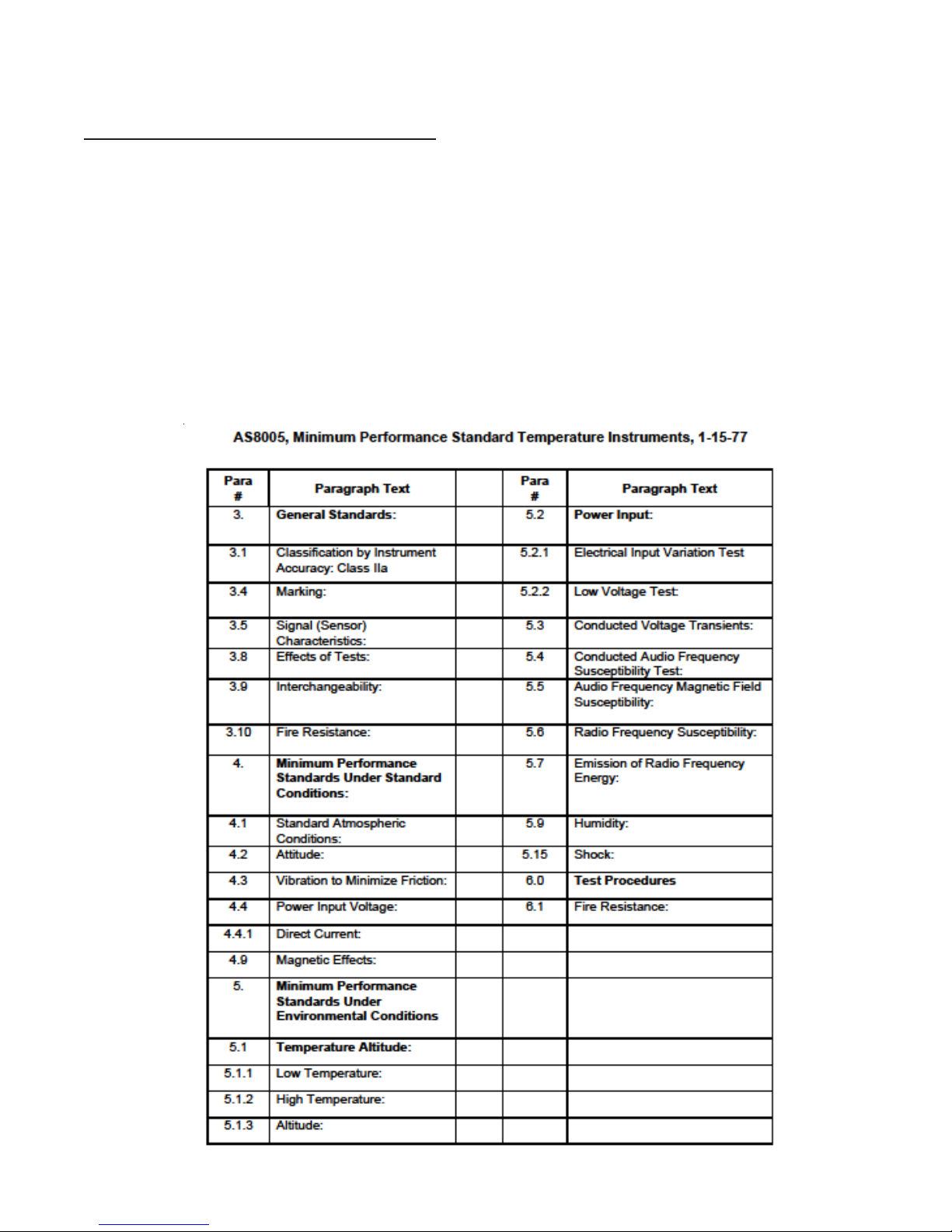
2.8 SAE Standards, TSOs and MPS:
The EDC-33xx-( ) articles carry the following TSO authorization:
TSO-C43c, Temperature
TSO-C44c, Fuel Flow
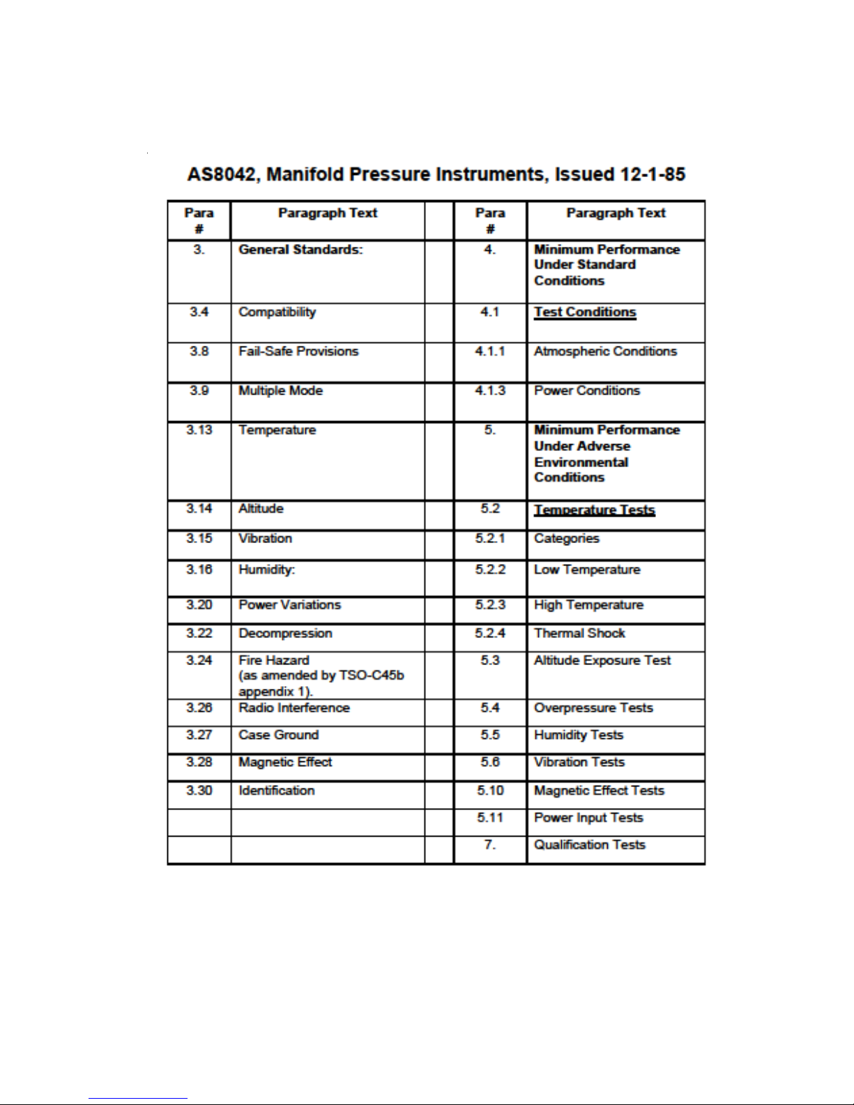
TSO-C45b, ManifoldPressure
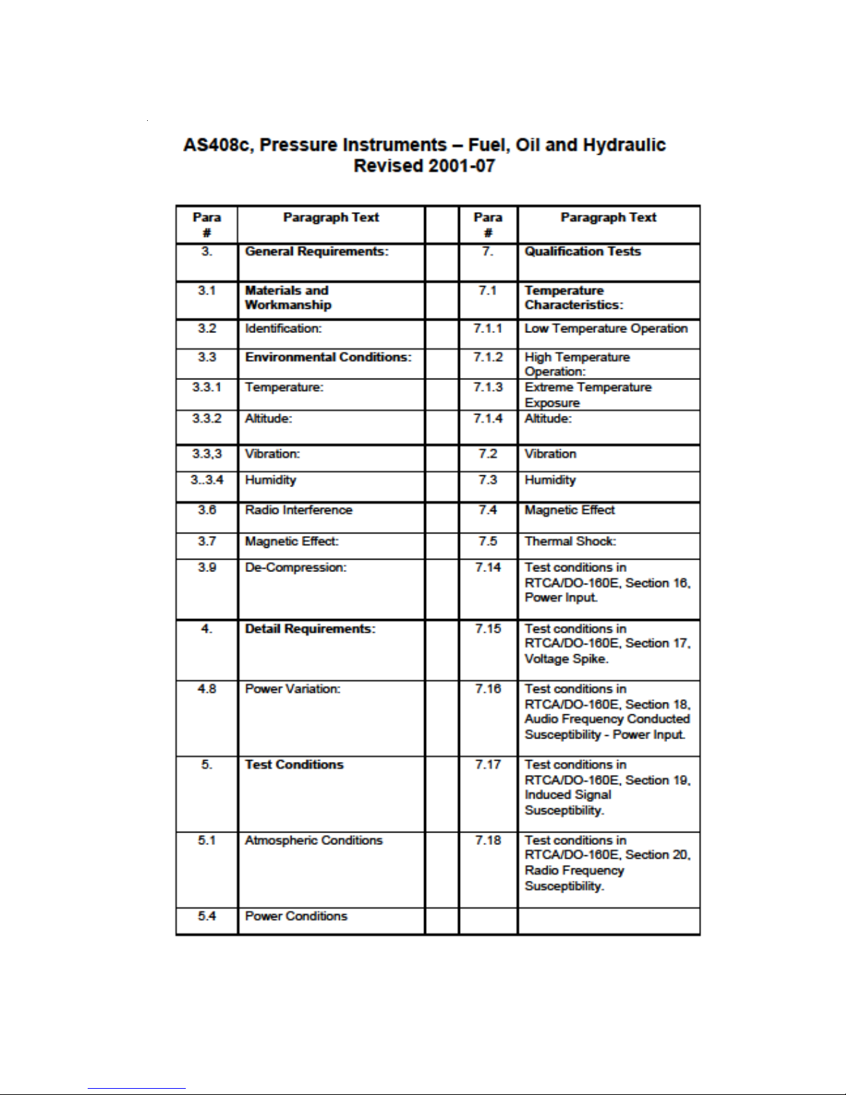
TSO-47a, Fuel, Oil and Hydraulic Pressure
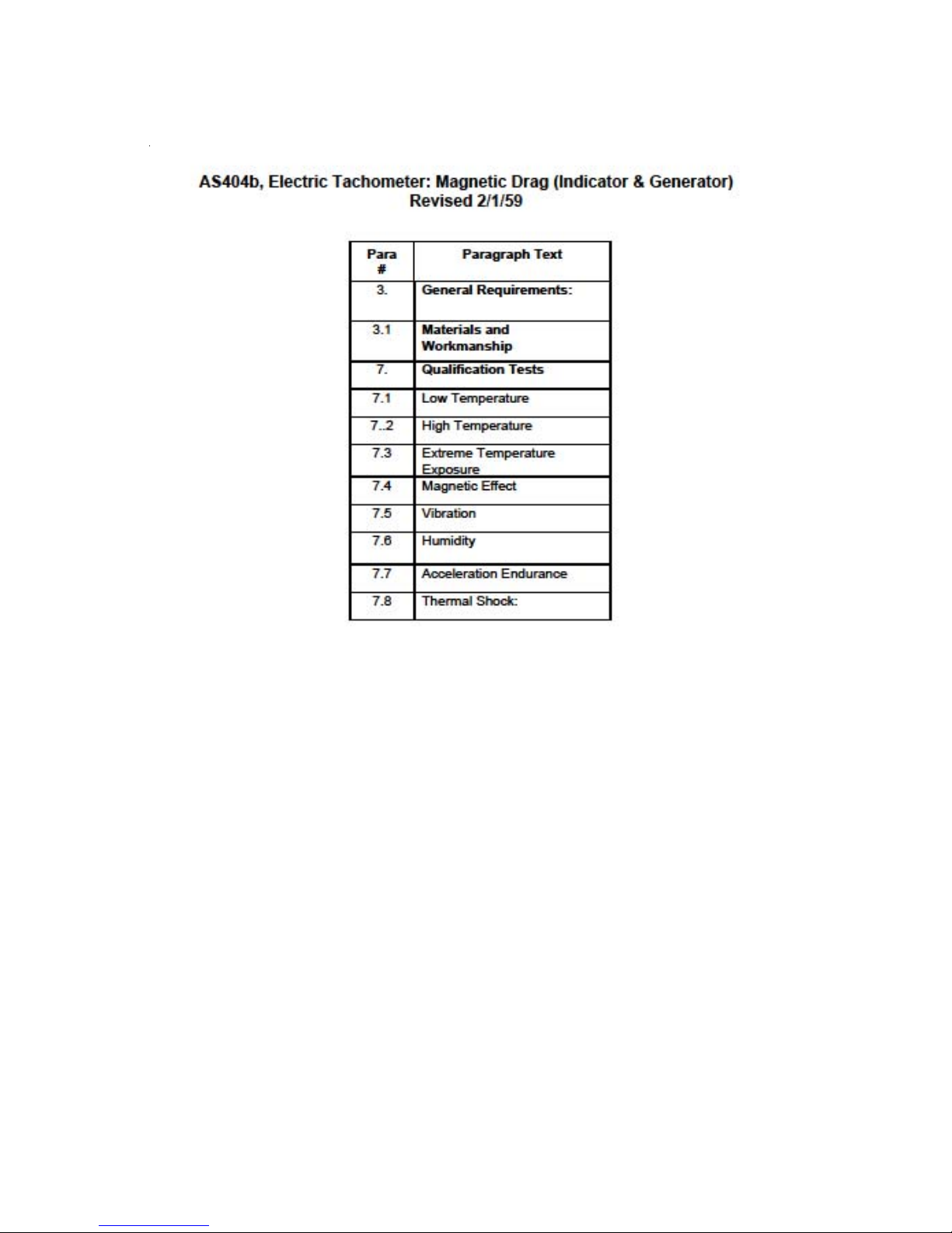
TSO-C49b, ElectricTachometer
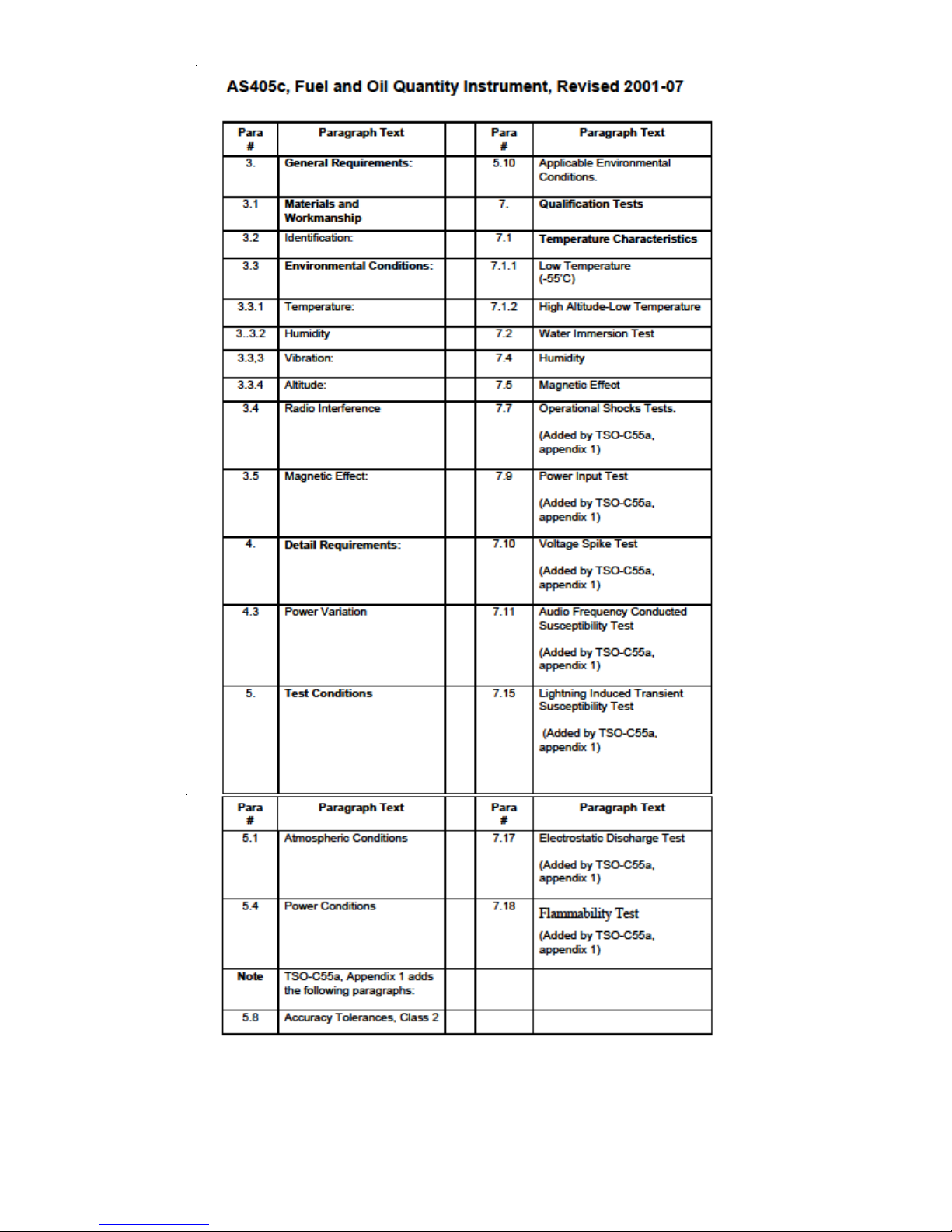
TSO-C55a, Fuel and Oil Quantity
AdeviationtouseDO-160GinplaceofolderversionlistintheapplicableTSOwasapprovedbytheFAA.
The EDC-33xx-( ) are incomplete articles that meet the following applicable MPS for the given SAE aeronauti-
cal standards list in the above TSO's:

6
7
8
9
10
11
3.0 Sample Wiring diagram
DB-37 Back View, Wire Side 37
19
20
1
DB-37 (421-0338-00)
Pin (421-0301-00)
Btm Connector
20
21
Gnd
37
36
35
N/C Used to key the connectors.
1Pulse 6 2Pulse 7 3Pulse 8
22
23Analog 16 - 5
Analog 16 +
24Analog 15 - 6
Analog 15 +
25Analog 14 - 7
Analog 14 +
26
Analog 13 - 8
Analog 13 +
4Gnd
9
Temp Comp 27Temp Comp Gnd
28
+5V 10
Analog 12 - 11Analog 12 +
30
+5V 12Analog 11 - 13Analog 11 +
32
+5V
Analog 10 - 15
Analog 10 +
31Gnd
33Gnd
34+5V 16Analog 9 - 17Analog 9 + 18Gnd
19Gnd
<1 to >80K Hz, Trig = .386V/0V
<1 to >80K Hz, Trig = .386V/0V
<1 to >80K Hz, Trig = .386V/0V
RTD Current Source
Temp Comp RTD
Not Used
Not Used
14
29
Gnd
-0.8V to 10.2V
-0.8V to 10.2V
-0.8V to 10.2V
-0.8V to 10.2V
-0.8V to 10.2V
-0.8V to 10.2V
RTD Current Source
Top Connector
Power 1
Gnd 2
Power In, (9 to 65 Volts).
DB-37
3
4
31
9
18
LSS
20
21 Gnd In
Output P ort
5
24
Gnd
6
N/C
7
8
USB -
USB +
USB 2.0
25
26
27
USB Shield
28
29
N/C
No Connect
No Connect
10
11
OC1
OC2
Open Col lec tor, Not Used
Open Col lec tor, Not Used
Open Collector
30Gnd
12
13
14
15
EEC Data 2
EEC Clk 2
EEC Data 1
EEC Clk 1
32
Gnd
Gnd
16
+8.5V
17
Pulse 2
33
Gnd
Pulse 1
<1 to >80K Hz, Trig = 21.5mV / 11mV
19
34
+8.5V
Gnd
37
36
35
N/C Used to key the connectors.
To Display Unit
<1 to >80K Hz, Trig = 21.5mV / 11m
V
Logic In, Trig = .59/.46V
Logic In, Trig = .59/.46V
Logic In, Trig = .59/.46V
Logic In, Trig = .59/.46V
20
21
Gnd
37
36
35
N/C Used to key the connectors.
1Pulse 3 <1 to >80K Hz, Trig = .386V/0
V
2
Pulse 4
3Pulse 5
22
23Analog 8 -
5
Analog 8 +
24
Analog 7 -
6Analog 7 +
25Analog 6 -
7
Analog 6 +
26Analog 5 -
8Analog 5 +
4
Gnd
9Temp Comp Temp Comp RTD or Ext RTD
27
Temp Comp Gnd
28
+5V
10Analog 4 -
+5V
11Analog 4 +
30
+5V
12Analog 3 -
Current for RTD
13
Analog 3 +
32+5V
14Analog 2 -
Current for RTD
15Analog 2 +
31Gnd
33Gnd
34
+5V
16Analog 1 -
Current for RTD
17
Analog 1 +
18Gnd
19
Gnd
<1 to >80K Hz, Trig = .386V/0
V
<1 to >80K Hz, Trig = .386V/0
V
9.537uV Resolution,
-0.2V to 2.5V,
29
Gnd
-0.8V to 10.2V
RTD In
-.2 to 5V CMV
" " "
" " "
" " "
RTD In
RTD In
Mid Connector
DB-37
1.8V/1.2V
1.8V/1.2V
1.8V/1.2V
1.8V/1.2V
-4Vto50V
-0.2Vto2.5V
-0.2Vto2.5V
9.537uVResolution
.2to5V CMV
9.537uVResolution
.2to5V CMV
-0.8Vto10.2V
21.5mV/11mV
21.5mV/11mV
-4Vto50V
-4Vto50V

12
This manual suits for next models
3
Table of contents


