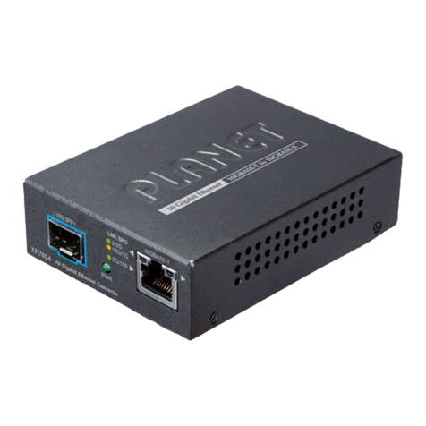
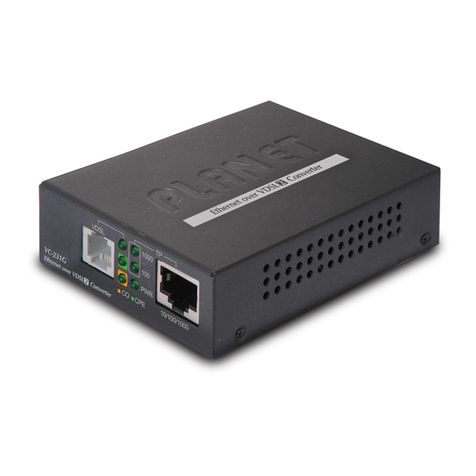
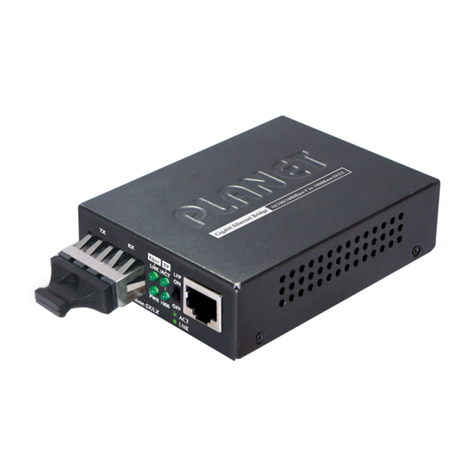
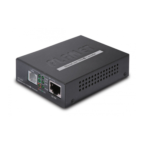
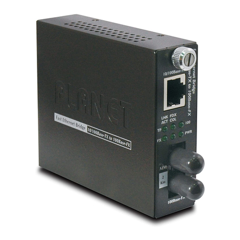
Planet GTP-805A User manual

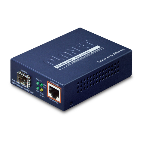
1000BASE-X to 10/100/1000BASE-T
802.3at PoE Media Converter
GTP-805A
User’s Manual

Trademarks
Copyright © PLANET Technology Corp. 2016.
Contents are subject to revision without prior notice.
PLANET is a registered trademark of PLANET Technology Corp.
The information in this manual is subject to change without
notice. All other trademarks belong to their respective owners.
Disclaimer
PLANET Technology does not warrant that the hardware will
work properly in all environments and applications, and makes
no warranty and representation, either implied or expressed,
with respect to the quality, performance, merchantability, or
tness for a particular purpose.
PLANET has made every effort to ensure that this User’s Manual
is accurate; PLANET disclaims liability for any inaccuracies or
omissions that may have occurred.
Information in this User’s Manual is subject to change without
notice and does not represent a commitment on the part of
PLANET. PLANET assumes no responsibility for any inaccuracies
that may be contained in this User’s Manual. PLANET makes no
commitment to update or keep current the information in this
User’s Manual, and reserves the right to make improvements
to this User’s Manual and/or to the products described in this
User’s Manual, at any time without notice.
If you nd information in this manual that is incorrect,
misleading, or incomplete, we would appreciate your comments
and suggestions.

FCC Warning
This equipment has been tested and found to comply with the
regulations for a Class A digital device, pursuant to Part 15 of
the FCC Rules. These limits are designed to provide reasonable
protection against harmful interference when the equipment
is operated in a commercial environment. This equipment
generates, uses, and can radiate radio frequency energy and, if
not installed and used in accordance with this user’s guide, may
cause harmful interference to radio communications. Operation
of this equipment in a residential area is likely to cause harmful
interference, in which case the user will be required to correct
the interference at his own expense.
CE Mark Warning
This is a Class A product. In a domestic environment, this
product may cause radio interference, in which case the user
may be required to take adequate measures.
Energy Saving Note of the Device
This power required device does not support Standby mode
operation. For energy saving, please remove the DC-plug to
disconnect the device from the power circuit. Without removing
the DC-plug, the device will still consume power from the
power source. In view of Saving the Energy and reducing the
unnecessary power consumption, it is strongly recommended to
remove the DC-plug if this device is not intended to be active.

WEEE Warning
To avoid the potential effects on the environment and
human health as a result of the presence of
hazardous substances in electrical and electronic
equipment, end users of electrical and electronic
equipment should understand the meaning of the crossed-out
wheeled bin symbol. Do not dispose of WEEE as unsorted
municipal waste and have to collect such WEEE separately.
Revision
PLANET 1000BASE-X to 10/100/1000BASE-T 802.3at PoE+ Media
Converter User’s Manual
For Model: GTP-805A
Rev 1.2 (October, 2016)
Part No. EM-GTP805A_V1.2 (2350-AA4480-002)

Table of Contents
1. Overview ......................................................................... 6
2. Checklist .......................................................................... 7
3. Product Outlook................................................................ 8
4. Link Fault Passthrough (LFP)............................................ 10
5. Installing the Converter................................................... 13
6. PoE Function .................................................................. 14
7. LED Indication ................................................................ 16
8. Cable Connection Parameter ............................................ 17
9. GTP-805A Technical Specications .................................... 18
APPENDIX A ....................................................................... 19
A.1 Device’s RJ45 Pin Assignments................................... 19
A.2 RJ45 Cable Pin Assignment........................................ 20
A.3 Fiber Optic Cable Connection Parameter ..................... 21

6
1. Overview
Thank you for purchasing PLANET GTP-805A 1000BASE-X Fiber-
optic to 10/100/1000Mbps Ethernet twisted-pair 802.3at PoE
Bridge Converter. This converter is used to convert one type of
media signal to other type that allows two segments to connect
easily, efciently and inexpensively. The converter provides
Power over Ethernet power injector function which is able to
drive one IEEE 802.3at/802.3af compliant powered device.
About the Power over Ethernet Injector
The GTP-805A is an IEEE 802.3at/802.3af Power over Ethernet
Injector that provides 54V DC over Ethernet cables. To insert
DC voltage into Cat.5/5e/6 cables, allow the cable between the
Injector (GTP-805A) and PoE PD (Powered Device) to transfer
data and power simultaneously. The maximum distance between
the Injector (GTP-805A) and PoE PD is 100 meters. The
GTP-805A combines the Ethernet digital data with power over
the twisted-pair cables as an IEEE 802.3at/802.3af Power over
Ethernet Injector. And using the Power over Ethernet splitter, it
can separate the digital data and the power into two outputs.
The benets of PLANET GTP-805A are cost saving, easy for
networking planning and higher reliability. What’s more, once
any IEEE 802.3at/802.3af devices are installed, the GTP-805A or
PD can make the connection while migrating and the Ethernet
digital packets, such as connecting the GTP-805A to an IEEE
802.3at/802.3af complied device, wireless AP or IP Camera.

7
2. Checklist
Your GTP-805A box should contain the following items:
l1000BASE-X to 10/100/1000BASE-T 802.3at PoE Media
Converter x 1
lUser’s Manual x 1
lAC-DC Adapter (Input: 54V DC, 0.74A max.) x 1
If any of these are missing or damaged, please contact your
dealer immediately; if possible, retain the carton including the
original packing material, and use them again to repack the
product in case there is a need to return it to us for repair.
Note
The GTP-805A comes with one vacant SFP module
slot. The mini GBIC SFP module is not bundled
with the product.

8
3. Product Outlook
Overview
The layout of the GTP-805A
52V~56V DC
LFP
PWR
Mini-GBIC
OFF ON
Fiber TX
LNK
ACT
In Use
PoE
10/100/1000Base-T
PoE Media Converter
1000X to 10/100/1000T
Power over Ethernet
Ethernet+DC
IEEE 802.3at PoE Media Converter
1000Base-X to 10/100/1000Base-T
Figure 3-1: Product Outlook of the GTP-805A
Left View
There are one RJ45 twisted-pair jack (auto-MDI/MDI-X), one
ber-optic connector (vary by model) and four LED indicators.
PWR
Mini-GBIC Fiber TX
LNK
ACT
In Use
PoE
10/100/1000Base-T
PoE Media Converter
1000X to 10/100/1000T
Ethernet+DC
Figure 3-2: Left View of the GTP-805A

9
Right View
There is one DIP switch for Link Fault Passthrough (LFP)
feature. It is turned on for LLCF and LLR detection but this
feature is not operable when turned off. Please refer to the
following sections for more. There is also one DC 52V ~ 56V
power socket for the PoE+ Media Converter.
52V~56V DC
LFP
OFF ON
Figure 3-3: Right View of the GTP-805A

10
4. Link Fault Passthrough (LFP)
The LFP function includes the Link Fault Passthrough function
(LLCF/LLR) and the DIP switch design. LLCF/LLR can
immediately alert administrators to the problem of the link
media and provide an efcient solution to monitoring the net.
The DIP switch’s LFP function can be disabled or enabled.
LLCF (Link Loss Carry Forward) means when a device is
connected to the converter and the TP line loses the link, the
converter’s ber will disconnect the transmission link. LLR
(Link Loss Return) means when a device is connected to the
converter and the ber line loses the link, the converter’s ber
will disconnect the transmission link. Both can immediately alert
administrators to the problem of the link media and provide an
efcient solution to monitoring the net.
Link Loss Carry Forward (LLCF)
The GTP-805A incorporates an LLCF function for troubleshooting
a remote connection. When LFP function is enabled, the FL and
TP ports do not transmit a link signal until they receive a link
signal from the opposite port.
The diagram below shows a typical network conguration with
a good link status using the GTP-805A for remote connectivity.
Media
Converter
Management
Station
Switch/Hub
w/SNMP
Management
Station
Media
Converter
Switch/Hub
w/SNMP
TP TP
Fiber
Cable
LFP ONLFP ON
lLED lit = established link °LED unlit = no link

11
If the connection breaks, the GTP-805A that loses the link
will forward to the Switch/Hub that generates a trap to the
management station. The administrator can then determine the
source of the problem.
Media
Converter
Management
Station
Switch/Hub
w/SNMP
Management
Station
Media
Converter
Switch/Hub
w/SNMP
TP TP
Broken
Fiber
Cable
LFP ONLFP ON
lLED lit = established link °LED unlit = no link
* Units are shipped with the LFP function being disabled (OFF).
Link Loss Return (LLR)
The ber ports of the GTP-805A have been designed with an
LLR function for troubleshooting a remote connection. LLR works
in conjunction with LLCF.
When LFP function is enabled, the port’s transmitter is shut
down when its receiver fails to detect a valid receive link. LLR
should only be enabled on one end of the link and is typically
enabled on either the unmanaged or remote device.
The diagram below shows a typical network conguration with
a good link status using the GTP-805A for remote connectivity.
Note that LLR and LLCF are enabled as indicated in the diagram.
Media
Converter
Management
Station
Switch/Hub
w/SNMP Station
Media
Converter Switch/Hub
Fiber
Cable
LFP OFFLFP ON
lLED lit = established link °LED unlit = no link

12
If one of the optical conductors is down (as shown in the
diagram box below), the converter with LLR function will return
a no-link condition to its link partner. With LLCF function also
enabled, the no-link condition is carried forward to the switch/
hub where a trap is generated to the management station, and
the administrator can then determine the source of the loss.
Media
Converter
Management
Station
Switch/Hub
w/SNMP Station
Media
Converter
Management
Switch/Hub
TP TP
Broken
Fiber
LFP ONLFP ON
lLED lit = established link °LED unlit = no link
Port 2 Port 1
Link Loss Carried Forward
Link Loss Returned
Link Loss Carried Forward
Note
LFP function is turned off by default. This feature
can also be turned on via the DIP-switch. If
you are familiar with the network installation
and for diagnostic purpose (i.e. check which
end is broken), you can turn it on and reset the
converter to make it effective. Otherwise, please
put it in the default position.

13
5. Installing the Converter
Please follow these steps to install the PoE+ Media converter:
lTurn off the power of the device/station in a network to which
the GTP-805A will be attached.
lEnsure that there is no activity in the network.
lAttach ber cable from the GTP-805A to the ber network.
lAttach a Cat.5/5e/6 UTP cable from the 10/100/1000BASE-T
network to the RJ45 port on the GTP-805A.
lConnect the 52V~56V DC power adapter to the GTP-805A
and verify that the Power LED lights up.
lTurn on the power of the device/station; the TX Link and FX
Link LEDs should light up when all cables are attached.
1000BASE-SX/LX
SFP Transceiver
10/100/1000BASE-T UTP
1000BASE-SX/LX
LC Fiber
PoE
Figure 5-1: GTP-805A Installation
Note
RJ45/STP, UTP Cat5/5e/6, straight/crossover cable
is accepted.
Please refer to section 8 for more about the wiring
distance of your TP, optic-fiber networks.

14
6. PoE Function
The installation of the GTP-805A and the IEEE 802.3at/802.3af
Injector/Splitter
Before your installation, it is recommended to check your
network environment. If there is any IEEE 802.3at/802.3af
devices that need to be powered on, the GTP-805A can provide
you a way to supply power for this Ethernet device conveniently
and easily.
The GTP-805A equips an AC-DC adapter with DC 54V input and
it injects the DC power into the pin of the twisted-pair cable
(Pins 1, 2, 3 and 6).
550m~120km 100 meters
PoE+
Speed Dome
Fiber Switch
1000
PoE
GTP-805A
1000BASE-SX/LX Fiber-optic
1000
PoE
1000BASE-T UTP with PoE
Power
DataData
Power DC 52V~56V

15
For the places hard to nd the power inlet, the GTP-805A
provides the easiest way to power your Ethernet devices such
as PLANET IEEE 802.3at/802.3af Power over Ethernet Splitter
(POE-152S/162S) with Internet Camera or PoE Wireless Access
Point installed in a wide-range place.
550m~120km 100 meters
Fiber Switch
1000
GTP-805A
1000BASE-SX/LX Fiber-optic
1000
PoE
1000BASE-T UTP with PoE
Data
PoE Splitter IP Camera
PoE
Power
Data
DC
Power DC 52V~56V

16
7. LED Indication
System
LED Color Function
PWR Green Light Indicate the device is powered.
10/100/1000BASE-T Port
LED Color Function
LNK/
ACT Green
Blink
Indicate that the PoE+ Media
Converter is actively sending or
receiving data over that port.
Light Indicate that the port is link up
at 10/100/1000Mbps.
Off Indicate that the port is link
down.
PoE in
Use Orange
Light
Indicate that the port is providing
DC 54V to remote powered
device.
Off
Indicate that the port is not
providing DC 54V to remote
powered device.
1000BASE-X Fiber Port
LED Color Function
LNK/
ACT Green
Blink
Indicate that the PoE+ Media
Converter is actively sending or
receiving data over that port.
Light Indicate that the port is link up.
Off Indicate that the port is link
down.

17
8. Cable Connection Parameter
The limitations are as below:
Duplex Connection Limitation (max.)
Twisted-pair
Half/Full Node to Node
Node to Switch/Hub 100 meters
Multi/Single Mode Converters
Full Node to Node
Node to Switch
GTP-805A:
Vary on SFP module

18
9.GTP-805ATechnicalSpecications
The GTP-805A comes with the following standard features:
lStandard: IEEE 802.3/802.3u/802.3ab, 10/100/1000BASE-T
and IEEE 802.3at/802.3af Power over Ethernet standard
lConnectors:
One RJ45 (auto-MDI/MDI-X) twisted-pair, EIA568 with PoE
One ber-optic connector type (vary with model)
lData Transfer Rate: 10/100/1000Mbps (TP), 1000Mbps
(Fiber)
lDuplex Mode Support: Full- or half-duplex mode by auto-
negotiation (TP)
lLED Indicators: PWR, FX LNK/ACT, TP LNK/ACT, PoE in Use
lPoE Power Output: DC 54V, 30 watts
lPower Pin Assignment: 1/2(+), 3/6(-)/end-span
lPower Supply: DC 54V, 0.74A, external AC-DC adapter
lAmbient Temperature: 0° to 50°C (operating)
lHumidity: 5% to 90% (non-condensing)
lDimensions: 26 x 70 x 94mm (H x W x D)
lCable:
UTP: Cat 5/5e/6 UTP cable
Fiber: MM: 50/125 µm or 62.5/125 µm optic ber
Fiber: SM: 9/125 µm optic ber
For connection to Router, Bridge, Switch or Hub, please refer to
the device’s Technical Manual.

19
APPENDIX A
A.1 Device’s RJ45 Pin Assignments
1000Mbps, 1000BASE-T
RJ45 Connector Pin Assignment
Contact MDI MDI-X
1BI_DA+ BI_DB+
2BI_DA- BI_DB-
3BI_DB+ BI_DA+
4BI_DC+ BI_DD+
5BI_DC- BI_DD-
6BI_DB- BI_DA-
7BI_DD+ BI_DC+
8BI_DD- BI_DC-
10/100Mbps, 10/100BASE-TX
RJ45 Connector Pin Assignment
Contact MDI Media Dependent
Interface
MDI-X Media Dependent
Interface-Cross
1Tx + (transmit) Rx + (receive)
2Tx - (transmit) Rx - (receive)
3Rx + (receive) Tx + (transmit)
4, 5 Not available
6Rx - (receive) Tx - (transmit)
7, 8 Not available

20
Implicit implementation of the crossover function within a
twisted-pair cable, or at a wiring panel, while not expressly
forbidden, is beyond the scope of this standard.
A.2 RJ45 Cable Pin Assignment
There are 8 wires on a standard UTP/STP cable and each wire is
color-coded. The following shows the pin allocation and color of
straight cable and crossover cable connection:
Straight Cable
Cross Over Cable
SIDE 1
SIDE 1
SIDE 2
SIDE 1
SIDE 2
12345678
12345678
12345678
12345678
SIDE 2
1 = White/Orange
2 = Orange
3 = White/Green
4 = Blue
5 = White/Blue
6 = Green
7 = White/Brown
8 = Brown
1 = White/Orange
2 = Orange
3 = White/Green
4 = Blue
5 = White/Blue
6 = Green
7 = White/Brown
8 = Brown
SIDE 1 SIDE 2
1 = White/Orange
2 = Orange
3 = White/Green
4 = Blue
5 = White/Blue
6 = Green
7 = White/Brown
8 = Brown
1 = White/Green
2 = Green
3 = White/Orange
4 = Blue
5 = White/Blue
6 = Orange
7 = White/Brown
8 = Brown
Figure A-1: Straight-through and Crossover Cables
Please make sure your connected cables are with same pin
assignment and color as with the above diagrams before
deploying the cables into your network.
Table of contents
Other Planet Media Converter manuals

Planet
Planet vc-234 vdsl2 User manual

Planet
Planet VC-201A User manual
Planet
Planet GT-702 User manual

Planet
Planet IXT-900-1X1T User manual

Planet
Planet FT-902 User manual

Planet
Planet FST-811 User manual

Planet
Planet GT-1205A User manual

Planet
Planet IPOE-171S User manual

Planet
Planet GT-805A User manual

Planet
Planet VF-101-T User manual

Planet
Planet FT-90X FT-902 User manual

Planet
Planet VC-231G User manual

Planet
Planet vc-234 vdsl2 User manual

Planet
Planet GT-702 User manual

Planet
Planet ICS-2100 User manual
Planet
Planet FT-701B User manual

Planet
Planet IXT-705AT User manual

Planet
Planet FT-801 User manual

Planet
Planet GEPON EPL-SPT-8 User manual

Planet
Planet IGT-900 Series User manual