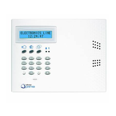
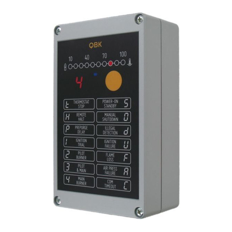
Electronics Line Commpact User manual

Installation Manual
ForquickinstallationinformationpleaserefertotheCommPact
QuickStartInstallationGuideprovidedonourwebsite:www.electronics‐line.com

ii
Table of Contents
1.Introduction ................................................................................................................................................................... 1
1.1.Documentation Conventions ..................................................................................................................................1
1.2.Specifications..........................................................................................................................................................2
1.3.System Overview....................................................................................................................................................3
1.4.Hardware Layout ....................................................................................................................................................4
2.System Installation........................................................................................................................................................ 7
2.1.Pre-Installation Planning.........................................................................................................................................7
2.2.Installation Procedure .............................................................................................................................................8
2.3.Back Tamper.........................................................................................................................................................12
2.4.Internet Communication Setup .............................................................................................................................12
3.Basic System Operation ............................................................................................................................................. 13
3.1.Front and Back Panel Layouts .............................................................................................................................13
3.2.Front Panel System Status LEDs .........................................................................................................................14
3.3.Front Panel Keypad ..............................................................................................................................................14
3.4.LCD Display..........................................................................................................................................................15
3.5.Audible Notification ...............................................................................................................................................16
3.6.Arming and Disarming ..........................................................................................................................................17
3.7.Additional Arming Options ....................................................................................................................................20
4.Advanced System Operation ...................................................................................................................................... 23
4.1.Menu Navigation...................................................................................................................................................23
4.2.Cancel Report.......................................................................................................................................................24
4.3.Zone Bypassing/Unbypassing ..............................................................................................................................24
4.4.User Codes...........................................................................................................................................................24
4.5.Follow-Me .............................................................................................................................................................27
4.6.Event Log..............................................................................................................................................................27
4.7.Service Menu........................................................................................................................................................28
5.Telecontrol and Two-Way Audio................................................................................................................................. 34
5.1.Incoming Calls ......................................................................................................................................................34
5.2.Outgoing Calls ......................................................................................................................................................36
6.PGM Control ................................................................................................................................................................ 38
6.1.Keyfob Control ......................................................................................................................................................38
6.2.Telephone Control ................................................................................................................................................38
7.Devices......................................................................................................................................................................... 39
7.1.Device Descriptors................................................................................................................................................39
7.2.Wireless Devices ..................................................................................................................................................39
7.3.Zones ....................................................................................................................................................................41
7.4.Keyfobs .................................................................................................................................................................45
7.5.Wireless Keypads .................................................................................................................................................46
7.6.Repeaters .............................................................................................................................................................47
7.7.Wireless Siren.......................................................................................................................................................47
8.Entry/Exit Timers and System Tones ......................................................................................................................... 49
8.1.Entry/Exit Delay ....................................................................................................................................................49
8.2.Arm on Exit ...........................................................................................................................................................49
8.3.Supplementary Entry Delay ..................................................................................................................................49
8.4.Entry Deviation......................................................................................................................................................50
8.5.Arming Tones........................................................................................................................................................50
8.6.System Trouble Tones..........................................................................................................................................51

iii
8.7.Tones Options.......................................................................................................................................................52
9.System Options ........................................................................................................................................................... 53
9.1.Code Lockout........................................................................................................................................................53
9.2.Arm/Disarm Options .............................................................................................................................................53
9.3.Panic Alarm...........................................................................................................................................................54
9.4.AC Loss Delay ......................................................................................................................................................55
9.5.Display Options.....................................................................................................................................................55
9.6.PGM Output Options.............................................................................................................................................56
9.7."No Arm" Indication...............................................................................................................................................58
9.8.Jamming Detection ...............................................................................................................................................58
9.9."No Motion" Time ..................................................................................................................................................58
9.10.Vocal Messages....................................................................................................................................................59
9.11.Installer Access.....................................................................................................................................................59
9.12.Daylight Savings ...................................................................................................................................................59
9.13.Entry/Exit Trouble .................................................................................................................................................59
9.14.Report Fail Trouble ...............................................................................................................................................60
9.15.Immediate Arming from WUApp ...........................................................................................................................60
10.Communications.......................................................................................................................................................... 61
10.1.System Reporting .................................................................................................................................................61
10.2.Report Cycles .......................................................................................................................................................63
10.3.Vocal Message Dialer...........................................................................................................................................63
10.4.Remote Programming...........................................................................................................................................65
10.5.Service Call...........................................................................................................................................................67
10.6.Communications Options......................................................................................................................................67
10.7.GSM Options ........................................................................................................................................................70
10.8.TWA Event Report Options ..................................................................................................................................72
10.9.Event Options for Central Station Reporting ........................................................................................................74
10.10.Vocal Message Dialer Event Options...............................................................................................................75
11.Internet Options ............................................................................................................................................................ 77
11.1.ELAS Connection Parameters..............................................................................................................................77
11.2.Control System Parameters..................................................................................................................................77
11.3.GPRS Network Parameters..................................................................................................................................78
12.System Initialization .................................................................................................................................................... 79
12.1.Initialization ...........................................................................................................................................................79
12.2.Default Program Restore ......................................................................................................................................79
12.3.Clear User Codes .................................................................................................................................................79
12.4.Clear Wireless Transmitters .................................................................................................................................79
Appendix A: Menu Structure ............................................................................................................................................... 80
Appendix B: Transmitter Installation .................................................................................................................................. 87
PIR Detectors (EL-2645/EL-2645PI) .................................................................................................................................87
Directional PIR (EL-2650XL) .............................................................................................................................................90
Wireless PIR (EL-2652SR) ................................................................................................................................................96
Magnetic Contact (EL-2601)............................................................................................................................................100
Universal Transmitter (EL-2602)......................................................................................................................................102
Glassbreak Detector (EL-2606).......................................................................................................................................103
Vibration Detector (EL-2607) ...........................................................................................................................................107
Smoke Detector (EL-2703) ..............................................................................................................................................109
Keyfobs (EL-2711M / EL-2711P / EL-2614E and EL-2714)............................................................................................117
1-Way Wireless Keypad (EL-2620) .................................................................................................................................118
Wireless Indication Keypad (EL-2621) ............................................................................................................................119

iv
Flood Detector (EL-2661) ................................................................................................................................................120
Gas Leak Detector (EL-2762)..........................................................................................................................................123
Carbon Monoxide Detector (EL-2764).............................................................................................................................126
Low Temperature Detector (EL-2663).............................................................................................................................131
Outdoor Siren and Strobe (EL-2626AC)..........................................................................................................................132
Repeater (EL-2635) .........................................................................................................................................................135
Transmitter Specifications ...............................................................................................................................................139
Appendix C: Web User Application ................................................................................................................................... 142
Appendix D: Event Table.................................................................................................................................................... 149
Appendix E: Zone Types .................................................................................................................................................... 152

Hata! Burada görünmesini istediğiniz metne Heading 1 uygulamak için Girişsekmesini kullanın. Hata! Burada
görünmesini istediğiniz metne Heading 1 uygulamak için Girişsekmesini kullanın.
CommPact Installation Manual
1
1. Introduction
ThismanualisdesignedtohelpyouinstalltheCommPactControlSystem1.Westronglyurgeyou
toreadthroughthismanual,initsentirety,beforebeginningtheinstallationprocesssothatyoucan
bestunderstandallthatthissecuritysystemhastooffer.Thismanualisnotintendedforenduser
use.Endusersareencouragedtoreadtheusermanualprovidedwiththesystem.Ifyouhaveany
questionsconcerninganyoftheproceduresdescribedinthismanualpleasecontactElectronicsLine
3000Ltd.at(+972‐3)963‐7777.
1.1. Documentation Conventions
Throughoutthemanual,wehavetriedtoincludealloftheoperatingandprogrammingfunctions
usingasimilarstructureandorderastheyappearinthemenu.Adetailedexplanationofhowto
navigatetheControlSystem’smenuisincludedinp.23,4.1MenuNavigation.Inordertosimplify
theproceduresthatappearintherestofthismanual,thefollowingconventionsareused:
Table 1-1: Documentation Conventions
Item… Description…
Select… Use the arrow keys to scroll through the options and press '√'
From the Event Log Menu,
select Clear Log.
Enter the main menu by pressing and entering your user code. Using the arrow
keys, navigate until you reach Event Log and press . Using the arrow keys,
navigate until you reach Clear Log and press '√'.
From the Service menu,
select Time/Date, Set
Date.
The same as above only this time you are navigating through three menu levels.
[7012] The shortcut to a specific menu item from the main menu. In this case, this is the
shortcut for Set Date. These appear in the procedures as an additional aid to
menu navigation.
[#5] A shortcut to a specific item in a sub-menu. For example, [#5] is the shortcut to
Bell enable disable in the sub-menu that is opened once you have selected the
detector you want to program.
√The symbol on a key that appears on the Front Panel keypad
5. Interface Test The text that actually appears on the CommPact LCD display (bold).
Due to the
occurrence
Important note, please pay attention.
The CommPact
Control System is
Caution: description of a potentially hazardous situation.
WarningDonottest
withflame!
Warning: description of a potentially hazardous situation that is a threat to
human life.
1The terms Control System, Control Panel, and CP refer to the same notion.

Hata! Burada görünmesini istediğiniz metne Heading 1 uygulamak için Girişsekmesini kullanın. Hata! Burada
görünmesini istediğiniz metne Heading 1 uygulamak için Girişsekmesini kullanın.
CommPact Installation Manual
2
1.2. Specifications
General
Zones: 32 wireless zones (1 transmitter per zone), 1
hardwire zone (Zone 33).
Wireless Keyfobs: 19 (Controlled or Non-controlled)
Wireless Keypads: up to 4, including one way or two-
way
Repeaters: 4
Wireless Siren: 1 (2-way)
User Codes: 32
Arming Methods: Full, Part or Perimeter.
Event Log: 1022 event capacity, time and date stamped
Weight: 1.350g
Dimensions: 210x153x40 mm
Communications
Event Reporting Accounts: up to 6, including Central
Station, Follow-Me, and Voice.
Telephone Numbers: 6 event reporting accounts, RP
Callback, Service Call.
Communication Interface Options: GPRS, GSM, PSTN.
Receiver
Type: Super-heterodyne, fixed frequency
Frequency: 418MHz, 868.35 or 433.92 (optional).
Data Encryption: SecuriCode™
Electrical*
Power Input: 230VAC, 50Hz, 120VAC, 60Hz/9VAC,
15VA (Model 1332)
AC Current Consumption: 30mA (alarm), 17mA
(standby)
DC Current Consumption: 280mA (alarm), 130mA
(standby)
Maximum Auxiliary Output Current Rating : 50mA
Battery low: below 7.15V
Backup Battery Pack: 4.8V 1.3Ah Part No. BT3021
(4 x 1.2 NiMH, size AA, rechargeable cells,)
The maximum charging current for the BT-5780 is 1.8 Ah
Fuse Ratings: 63mA/250V for 230VAC – Part No.
EF1063,
PGM Relay Output Contact Rating: 100mA (max. load)
Built-in Siren: 93dB @ 10ft
Tamper Switch: N.C.
Operating Temperature: -10°C to 55°C (14°F to 131°F)
*Themeasurementsarewithfullychargedbattery.ACcurrentwasmeasuredonfuseF1andDCcurrentwas
measuredonfuseF2.
!
Power connection to the unit should be according to the national electrical code for
permanent installation.
The power supply should be fed from a readily accessible disconnect device.
If the unit is permanently wired to the mains power, use a 2-pole disconnect device (15A max.)
and the wires should be min. 0.75mm2in a conduit of at least 16mm.
If the mains power is connected with a plug, the plug should be indicated as the disconnecting
device and the socket shall be max. 2m from the Control System.
Batteries shall be provided by a distributor and replaced by authorized service personnel.
The backup battery pack should be replaced every five years.
Batteries should be stored in a cool, dry place.

Hata! Burada görünmesini istediğiniz metne Heading 1 uygulamak için Girişsekmesini kullanın. Hata! Burada
görünmesini istediğiniz metne Heading 1 uygulamak için Girişsekmesini kullanın.
CommPact Installation Manual
3
1.3. System Overview
TheCommPactControlSystemisafull‐featuredwirelessControlSystemthatisexpectedto
provideasolutiontotheneedsofmostresidentialinstallations.Thissystemhasbeendeveloped
baseduponadesignconceptgearedtowardseasyinstallationanduse.Withthisinmind,theuser
interfaceisbasedonasimple,menu‐drivenmodelthatsuitstheessentialrequirementsofboththe
userandinstalleralike.YoucanprogramtheCommPactControlSystemon‐siteusingtheFront
PanelkeypadorPC,oroff‐siteviaaPCusinglocalprogrammingoptionoftheRemote
Programmer.
ThesystemoffersGPRSnetworkconnectivity,providinghigh‐speedcentralstationreportingviaa
GPRSinterface.
TheElectronicsLineApplicationServer(ELAS)handlesallcommunicationbetweenthesystem,
serviceprovidersandwebusersenablingmonitoringandcontroltobeperformedviatheWeb.
BackupcommunicationiscarriedoutviaPSTNorGSM.
Centralstationcommunicationandremoteparametersprogrammingandmaintenanceemploy
GPRS,GSMorstandardPSTNcommunication.SMSmessagingprovidesaninnovativemethod
usedforbothcentralstationandFollow‐Meusermonitoring.Additionally,SMSmessagescanbe
senttotheControlSystemenablingtheusertosendcommandstothesystemfromanywhereon
theplanet.
Figure1‐1showsthecomponentsthatmakeupthesystemandthesystem’sinteractionwith
externalcommunicationnetworksforalltheavailableconfigurations.

Hata! Burada görünmesini istediğiniz metne Heading 1 uygulamak için Girişsekmesini kullanın. Hata! Burada
görünmesini istediğiniz metne Heading 1 uygulamak için Girişsekmesini kullanın.
CommPact Installation Manual
4
Figure 1-1: System Architecture
1.4. Hardware Layout
Theaimofthissectionistoacquaintyouwiththecircuitboardsthatmakeupthesystem.The
CommPactControlSystemhousinghastwoPCBs:theMainBoardandthePowerSupplyand
ConnectionsBoard.

Hata! Burada görünmesini istediğiniz metne Heading 1 uygulamak için Girişsekmesini kullanın. Hata! Burada
görünmesini istediğiniz metne Heading 1 uygulamak için Girişsekmesini kullanın.
CommPact Installation Manual
5
1.4.1. Main Board
TheMainBoardisthebrainofthesystem.ItcoordinatesalltheControlSystemactivity.
TheMainBoard(seeFigure1‐2)enablesGSMandGPRScommunicationthatallowsreporting
eventstotheCentralStationsendorreceiveSMSmessages,implementcellularTwo‐WayAudio
andremotesoftwareupdate.
ThisBoardalsohasastandarddialerforcommunicationviathePublicSwitchedTelephone
Network(PSTN).Backupcommunicationwitheventreporting,andTwo‐WayAudio(TWA)are
alsoavailableviaPSTN.
TheMainBoardalsohasconnectorstotheBuilt‐inSirenandtheSpeaker.
Additionally,theMainBoardincludesaUSBportforPCprogramming.
Back View Front View
Figure 1-2: Main Board
1. Built-in Siren Connector
2. Buzzer
3. Flash Programming Connector
4. LCD Contrast Control
5. USB Port
6. SIM-Card Holder
7. Speaker Connector
8. Flat-Cable Interface Connector to the Power
Supply and Connections Board
9. Microphone
10. Front Panel Keypad
11. GSM Engine
12. LCD Display
DonotuseVoIPphonelinesforcommunicationtothecentralmonitoringstation.
Incertaincasesthesystemmaynottransmitalarmsignalssuccessfullyoverthe
VoIPnetwork.
Toreducetheriskoffire,useonlyNo.26AWGorlargertelecommunicationwire.
Flatcable(8)isnotRemovable!

Hata! Burada görünmesini istediğiniz metne Heading 1 uygulamak için Girişsekmesini kullanın. Hata! Burada
görünmesini istediğiniz metne Heading 1 uygulamak için Girişsekmesini kullanın.
CommPact Installation Manual
6
1.4.2. Power Supply and Connections Board
Asthenamesuggests,thePowerSupplyandConnectionsBoardhastheACandbatteryconnectors,
powerconnectionfuses,andthetransformer.ThisBoardalsoservesastheinterfacetothePGM
programmableoutput,theHardwireZone,Telephone,TelephoneLine,andBackTamper.Ontherear
sideoftheBoard,thereisabatteryswitchthatallowsapplyingbatterypoweratfirstinstallation.
Figure 1-3: Power Supply and Connections Board
1. AC Power Connector
2. AC Fuse
3. Terminal Block
4. Telephone Line Fuse
5. Back Tamper Connector
6. Transformer
7. Front Tamper Switch
8. Flat-Cable Interface Connector to the
Main Board
9. Battery Fuse
10. Battery Connector

Hata! Burada görünmesini istediğiniz metne Heading 1 uygulamak için Girişsekmesini kullanın. Hata! Burada
görünmesini istediğiniz metne Heading 1 uygulamak için Girişsekmesini kullanın.
CommPact Installation Manual
7
2. System Installation
Thefollowingchapterexplainshowtoinstallthesystemandprovidesguidelinesandtipsonhow
tooptimizetheinstallation.
Itisrecommendedthatyoufamiliarizeyourselfwiththevariouscircuitboardsthatmakeupthe
system–seep.4,1.4HardwareLayout.
2.1. Pre-Installation Planning
Beforestartingtheinstallationprocedure,itisworthwhiletodrawaroughsketchofthebuilding
anddeterminetherequiredpositionfortheControlSystemandeachwirelessdevice.
Whendecidingontheplacementforinstallation,considerthefollowing:
MounttheControlSysteminalocationwitheasyaccesstotelephoneandpower
connections.
MounttheControlSysteminalocationthatprovideseasyconnectiontotherouter.
ForbestperformanceoftheGPRSCommunication,theControlSystemshouldbe
mountedinapositionwheretheGSMsignalisstrong.
Refertothefollowingsectioninordertochoosetheoptimallocationforwireless
devicesinrelationtotheControlSystem.
2.1.1. Wireless Installation Guidelines
Inordertooptimizewirelesscommunication,considerthefollowingguidelines:
Wheneverpossible,mounttheControlSystemcentrallyinrelationtowireless
detectors.
Avoidinstallationincloseproximitytosourcesofhighnoiseorradiofrequency
interference.Forexample,metalairconditioner/heaterductsandcircuitbreaker
boxes.
MinimizethedistancebetweentheControlSystemandtransmitters.
MinimizethenumberofobstaclesbetweentheControlSystemandtransmitters.
Figure 2-1: Minimizing Obstacles
Metalbasedconstructionmaterials,suchassteelreinforcedconcretewalls,reducethe
rangeofradiotransmissions.
Figure 2-2: Considering Construction Materials

Hata! Burada görünmesini istediğiniz metne Heading 1 uygulamak için Girişsekmesini kullanın. Hata! Burada
görünmesini istediğiniz metne Heading 1 uygulamak için Girişsekmesini kullanın.
CommPact Installation Manual
8
ThereductionoftheRFsignals’strengthisdirectlyproportionaltothethicknessof
theobstacle,assumingthattheobstaclesareofidenticalmaterial.
Figure 2-3: Considering Thickness of Obstacles
2.2. Installation Procedure
TheCommPactControlSystemKitconsistsof:
ControlSystem
QuickStartInstallationGuide
QuickUserGuide
MountingGuide
PlasticbagwithCableClamp,CableClampscrew,HousingScrew,
Afterunpackingthekitandmakingcertainthatyouhaveallthenecessaryequipment,itis
recommendedthatyouinstallthesystemasfollows:
STAGE1:TemporarilypowerupthesystemandinstalltheSIMcard.
STAGE2: Selectinglanguageanddefaults
STAGE3: Registerthetransmitters.
STAGE4:Testthechosenmountinglocation.
STAGE5:ProgramtherelevantInternetoptions.
STAGE6:PermanentlyInstalltheControlSystemandTransmitters
2.2.1. Stage 1 – Temporarily Power Up the System
Inordertoregisterandtesttransmitters,itisnecessarytotemporarilypoweruptheControlSystem
beforepermanentlyinstallingit.
1. Insertascrewdriverbetweenthefrontandbackpanelsofthehousing;carefullytwistit
toreleasethetabs(seep.8,Figure2‐4).
Figure 2-4: Opening the Housing
2. ThreadthePowerACcablethroughtheholeinthebackcover.ConnectittotheACcable
connectoronthePCBandsecureitbyCableClamp(seep.9,Figure2‐5).
TheControlSystemissuppliedwithoutACcable.PleaseuseStandardTwo‐PinEuropean
Plugcableonly.FortheCableClamp,usethescrewandthewashersuppliedinyourkitto
replacethePCBscrew.

Hata! Burada görünmesini istediğiniz metne Heading 1 uygulamak için Girişsekmesini kullanın. Hata! Burada
görünmesini istediğiniz metne Heading 1 uygulamak için Girişsekmesini kullanın.
CommPact Installation Manual
9
3. OpentheSIMcardholderontheMainBoard;inserttheSIMcard*(seep.5,Figure1‐2).
4. ClosetheHousing.
5. PlugthePowerACcableintothewalloutlet.
Infiveminutessincepower‐up,thesirenwillsound.Tosilencethesiren,pressyouruser
code(defaultusercodeis1234).
Atthisstage,donotconnectthebackupbattery.Ignoreanytroubleconditionsthat
mayappearontheLCDDisplay(e.g.LowBattery).
Figure 2-5: Main Board Wiring Scheme
2.2.2. Stage 2: Selecting Language and Defaults
TheControlSystemsupportsseverallanguages.Languageanddefaultssettingsmustbedefined
beforeanyconfigurationparametersaresetoranytransmittersregistered.
SettinglanguageanddefaultsautomaticallyinitializestheControlSystem.Thismeansthat
allpriorconfigurationsettingsareresettothedefaultsettingsandallpreviouslyregistered
transmittersaredeletedfromtheControlSystem.
Toselectlanguageanddefaults:
1. Pressʹ√ʹ.
2. EnteryourInstallercode(thedefaultInstallercodeis1111).
3. FromtheProgrammingmenu,selectDevices[971].
4. Selectdefaultandpressʹ√ʹ.
5. Selectlanguage(Voice+LCDdisplay)andpressʹ√ʹ.
6. Pressʹ√ʹoncemoretoinitializetheControlSystem
2.2.3. Stage 3 – Register the Transmitters
FortheControlSystemtorecognizeadevice,itstransmittermustberegistered.Ingeneralterms,
transmitterregistrationmeanssendingtwotransmissionsfromadevicewhentheControlSystemis
inRegistrationmode.
Toregisteradevice:
1. Pressʹ√ʹ.
2. EnteryourInstallercode.
3. FromtheProgrammingmenu,selectDevices[91].
4. Selectthetypeoftransmitteryouwanttoregister.Forexample,ifyouwanttoregistera
wirelessdetectortoazone,selectZones.
*optional feature

Hata! Burada görünmesini istediğiniz metne Heading 1 uygulamak için Girişsekmesini kullanın. Hata! Burada
görünmesini istediğiniz metne Heading 1 uygulamak için Girişsekmesini kullanın.
CommPact Installation Manual
10
5. Selectthespecificdeviceyouwanttoregister(forexample,Zone4);thesysteminitiates
Registrationmode.DuringRegistrationmode,thesystemwaitsfortwotransmissions
fromthedevice.
Ifadevicehasalreadybeenregisteredattheselectedlocation,thesystemwillnotinitiate
Registrationmode.Ifthedevicehasalreadybeenregisteredatanotherlocation,attemptsto
registeritareignoredbythesystem.Zones1‐32areintendedforwirelessdetectors
6. Registerthedevice–refertoeachdevice’sinstallationinstructionsinAppendixBfor
furtherdetails.
7. Whentwotransmissionshavebeenreceived,Save?isdisplayed.
Pressʹ√ʹtoconfirmregistration.
8. Continueenteringotherparametersforthechosendevice.
9. PressΧtoexitmenumode.
2.2.4. Stage 4 – Test the Chosen Mounting Location
Onceallofthetransmittersareregistered,itisrecommendedthatyoutestthechosenmounting
locationsbeforepermanentlymountingtheControlSystemandwirelessdevices.Youcantestthe
transmittersignalstrengthusingtheTXTestfeature.
Totesttransmittersignalstrength:
1. Pressʹ√ʹ.
2. EnteryourInstallercode.
3. Enter[7072](Service,Transmitters,andTXTest)toinitiateTXTestmode.
4. Activatethetransmitteryouwishtotest;thetransmitter’sdetailsappearontheControl
System’sLCD.Additionally,betweenoneandfourtonesaresoundedtoindicatethe
transmitter’ssignalstrength.Iffourtonesaresounded,thetransmitterisinthebest
possiblelocation–seep.30,4.7.7Transmittersforfurtherinformation.
5. Afteryouhavetestedeachtransmitter,pressΧtoexitTXTestmode.
WhenusingGPRSand/orGSMcommunication,testtheGSMsignalstrength.
TotesttheGSMsignalstrength:
1. Pressʹ√ʹ.
2. EnteryourInstallercode.
3. Enter[7091](Service,RF&GSMlevel,GSMSignal);RFRSSIlevelmeasuredbythe
systemʹsreceiver–seep.31,4.7.9GSMSignalStrengthforfurtherinformation.
ChecktheRFRSSI(ReceivedSignalStrengthIndication)levelusingthesystem’sRSSImeter.
ToviewtheRFRSSIlevelreading:
Enter[7092](Service,RF&GSMlevel,RFRSSILevel);theRFnoisemeasuredbythe
systemʹsreceiverisdisplayed–seep.32,4.7.10RFRSSIlevelforfurtherinformation.

Hata! Burada görünmesini istediğiniz metne Heading 1 uygulamak için Girişsekmesini kullanın. Hata! Burada
görünmesini istediğiniz metne Heading 1 uygulamak için Girişsekmesini kullanın.
CommPact Installation Manual
11
2.2.5. Stage 5 – Program Internet Options
Internetsettingsaremostlypre‐programmedintheControlSystem’sdefaultsettings.Theonly
settingsyouneedtoprogramaretheControlSystem’sID&Password(providedbytheELAS
administrator).ThefollowingproceduresexplainhowtoprogramtheControlSystem’sID(CPID)
andPassword.ForfurtherinformationregardingotherInternetoptionsandsettings,seep.77,11
InternetOptions.
ToprogramtheCPID:
1. Pressʹ√ʹ.
2. EnteryourInstallercode.
3. Enter[9573](Programming,Communications,Internet,andCPID).
4. EnteranIDusingthealphanumerickeypad.TheIDlengthmustbesixuptosixteen
characters.TheIDmustbeginwithaletter.
5. Pressʹ√ʹ.
ToprogramtheControlSystem’spassword:
1. Pressʹ√ʹ.
2. EnteryourInstallercode.
3. Enter[9574](Programming,Communications,Internet,andCPPassword).
4. Enterapasswordusingthealphanumerickeypad.
Thepasswordlengthmustbesixuptosixteencharacters.Thepasswordmustbegin
withaletter.
5. Pressʹ√ʹ.
2.2.6. Stage 6 – Permanently Install the Control System and Transmitters
HavingchosenandtestedthemountinglocationoftheControlSystemandeachtransmitter,you
arenowreadytopermanentlyinstallthesystem.
Topermanentlyinstallthetransmitters,refertoeachdevice’sinstallationinstructionsinAppendix
Bofthismanualortothosesuppliedindividuallywitheachproduct.
ToinstalltheControlSystem:
1. Placethedrillingtemplateagainstthewallandmarkthemountingholes.
2. Install2wallanchorsandscrewsleaving2‐3mmoutofthewall.
TheControlSystemmustbemountedsothatitshallwithstandaforceofatleastthreetimes
itsownweight.
3. Disconnect(unplug)ACpowerfromtheControlSystem.
4. Openthehousing(seep.8,Figure2‐4).
5. Threadanyrequiredcablesthroughtheholeinthebackcover.
6. ConnecttheoptionalTelephoneLine,Telephone,WiredZone,andPGMtotheir
connectorsontheMainBoardterminalblock–seep.9,Figure2‐5.
7. PlugtheACpowercableintotheoutlet.
AlwaysconnectACpowerbeforeconnectingthebatterypack.Batteriesaresupplied
uncharged.Whenyoufirstconnectthebattery,itisprobablethatthesystemwilldisplaya
LowBatterycondition.Allowthebatterytochargeforatleast18hoursbeforeuse.
8. ConnecttheBackupBatterytoitsconnectorontheMainBoard–seep.6Figure1‐3.

Hata! Burada görünmesini istediğiniz metne Heading 1 uygulamak için Girişsekmesini kullanın. Hata! Burada
görünmesini istediğiniz metne Heading 1 uygulamak için Girişsekmesini kullanın.
CommPact Installation Manual
12
9. MounttheControlSystemtothewallbyhangingthebackcoverontothescrews.
Makesurethatthebacktamperisclosed.
10. Closethehousingmakingsurethatthefrontandbackcoversclickshut.Applythe
housingscrewatthebottomofthepanel.
2.3. Back Tamper
TheBackTamperswitchisanoptionalfeaturethatprovidesanextrasafeguardintheeventthatthe
ControlSystemisremovedfromthewall.
TheBackTamperswitchislocatedontherearsideoftheControlSystem’shousingandis
constantlydepressedwhilethepanelishangedtightlyonthescrew.
2.4. Internet Communication Setup
Afteryouhavepoweredupthesystem,theGPRSstartupsequenceisinitiated.Duringthis
sequence,theparametersprogrammedintheControlSystemʹsInternetOptions(see–p.77,11
InternetOptions)areactivated.Afterthestartupsequenceiscomplete,theControlSystemattempts
toconnecttotheELASGPRSProxy.
IftheControlSystemishavingdifficultyconnectingtoELAS,atroublemessageisdisplayed.The
followingtablesummarizesthetroublemessagesforthiscase.
Table 2-1: ELAS Connection Trouble Message
LCD Display Trouble condition Restored by
SIM CARD TROUBLE SIM card not recognized or incorrectly
programmed
Insertion of recognized SIM card
or correct programming.
MEDIA LOSS GSM Cellular network down Cellular network restore
DEVICE TROUBLE GSM Faulty GSM/GPRS module Replacement of faulty module
MEDIA LOSS GPRS
MODULE
Wrong GPRS settings (APN, Password
etc.) or loss of GPRS service
Correct GPRS settings or
restored GPRS service
XML FAIL Control panel fails to communicate with
the XML Proxy
Successful communication with
XML Proxy
Inthiscase,checkthattheControlSystem’sInternetOptionsarecorrectlyprogrammed.If
youstillexperienceproblems,theIPProtocolandGPRSsettingsmustbechecked.
TochecktheIPProtocolandGPRSsettings:
1. OpenthePCBCompartmentandmakesureaSIMCardwithGPRSsupportisonthe
PCB–seep.13Figure3‐2.
2. ClosethehousingandenteryourInstallercode.
3. Enter[95112](Programming,Communications,Accounts,Account1,andProtocol).
Ifthesettingiscorrect,youwillseeʺIPProtocolʺ.
4. ExitthismenuandEnter[95113](Programming,Communications,Accounts,Account1,
Interface).Ifthesettingiscorrect,youwillseeʺGPRSʺ.
WhenusingaSIMcardwithaPINcode,theinstallerhastomakesurethatthePINcode
programmedintheControlSystemisthesameastheSIMcardʹsPINcode–seep.8,
10.7.2PINCode.

Hata! Burada görünmesini istediğiniz metne Heading 1 uygulamak için Girişsekmesini kullanın. Hata! Burada
görünmesini istediğiniz metne Heading 1 uygulamak için Girişsekmesini kullanın.
CommPact Installation Manual
13
3. Basic System Operation
3.1. Front and Back Panel Layouts
Thefrontpanelprovidesadetailedinterfaceforoperatingandprogrammingthesystem.The
followingdiagramwillfamiliarizeyouwiththevariouselementsofthefrontpanel.
Figure 3-1: Front Panel
NextdiagramshowstheControlSystemʹsbackpanelthatprovidesaccesstotheSIMcard,theUSB
Connectorandthebatterypowerswitchusedatfirstinstallation–seeFigure3‐2below.
Figure 3-2: Back Cover
Alphanumeric
Keypad
Arming
Keys
LCD
Display
OK
LED
Arm
Status
LED
Menu
Navigation
Keys

Hata! Burada görünmesini istediğiniz metne Heading 1 uygulamak için Girişsekmesini kullanın. Hata! Burada
görünmesini istediğiniz metne Heading 1 uygulamak için Girişsekmesini kullanın.
CommPact Installation Manual
14
3.2. Front Panel System Status LEDs
ThetwoLEDs,OKandArmStatus,provideessentialinformationonthestatusofthesystem.
Table 3-1: OK LED Indication
OK LED Status Meaning
Off Both AC and Battery power are disconnected.
Green On System Power Status is OK and there is no System Trouble.
Green Flashing Open Zone. Check that the windows and doors are closed and no movement is
detected by the detectors within the protected area.
Yellow On System Trouble.
Yellow Flashing (slow) Backup battery low or low battery from transmitters.
Yellow Flashing (fast) AC loss.
Yellow Intermittent
On/Off
System Trouble in addition to AC loss/Low Battery.
Table 3-2: Arm Status LED Indication
LED Status Meaning
Off The system is disarmed.
Green On The system is armed.
Red Flashing An alarm has occurred. Alarm indication is cleared the next time you arm the
system or view the relevant arming event in the event log.
Alarmindicationisnotdisplayedafterasilentpanicalarm.
3.3. Front Panel Keypad
Thealphanumerickeypadonthefrontpanelenablesyoutoperformvariousoperationand
programmingtasks.ApartfromFull,Part,andPerimeterarming,thefrontpanelkeypadoffersa
numberofspecialfunctions.
Table 3-3: Front Panel Keypad Functions
Key Symbol used in
the text of this
manual
Special function
1Used to enter symbols in descriptor editing.
0Used to enter symbols in descriptor editing.
ΧUsed to cancel the current selection.
Used to return to the previous menu level.
√Used to enter Menu mode.
Used to select the current menu item.
Used to signify the end of an entered value.
Toggles status in Zone Bypass/Unbypass function.

Hata! Burada görünmesini istediğiniz metne Heading 1 uygulamak için Girişsekmesini kullanın. Hata! Burada
görünmesini istediğiniz metne Heading 1 uygulamak için Girişsekmesini kullanın.
CommPact Installation Manual
15
In descriptor editing, used to insert a space before the current
character
In phone number editing, used to enter "T", ",", "P", "+", "*", "#".
In account number editing, used to enter Hexadecimal digits (A-F).
Toggles item descriptors and default names.
In the event log, toggles the time/date stamp.
Toggles AM and PM when setting the time in 12hr format.
In descriptor and phone number editing, used to delete the current
character
Used to scroll backwards in the current menu level.
For Global Chime and Message Center features, used to access
shortcuts.
+ (Global Chime shortcut)
+ Χ(Record Message shortcut, front panel keypad only)
+ √(Play Message shortcut, front panel keypad only)
Used to scroll forwards in the current menu level.
During standby, used to scroll through the list of system trouble
conditions.
3.4. LCD Display
TheLCDdisplayprovidesyouwithadetailedinterfaceforoperationandprogramming.
Figure 3-3: Typical Standby Display
3.4.1. Standby Mode
StandbymodecanbedefinedasthestatethesystemisinwhenitisdisarmedandnotinMenu
mode.InStandbymode,thearmedstatus,systemstatus,orbannerisdisplayed.Ifsystemstatusis
normal,thecurrenttimeisdisplayed.
Table 3-4: Armed Status
Item… Description…
DISARMED The system is disarmed.
FULL ARMED
The system has been armed using the displayed arming method.
PART ARMED
PERIMETER ARMED
PART ARMED INST The system has been armed using the displayed arming method with the
Instant arm feature activated.
PERIM ARMED INST
FULL ARMING
The system is in the process of arming (displayed during exit delay).
PART ARMING
PERIMETER ARMING

Hata! Burada görünmesini istediğiniz metne Heading 1 uygulamak için Girişsekmesini kullanın. Hata! Burada
görünmesini istediğiniz metne Heading 1 uygulamak için Girişsekmesini kullanın.
CommPact Installation Manual
16
PART ARMING INST The system is in the process of arming with the Instant arm feature activated.
PERIM ARMING INST
Table 3-5: System Status
Item Description
ZONES IN ALARM Zones have been violated.
TAMPER ALARM The system has been tampered with.
56 TO EXIT The exit delay is counting down (56 seconds remaining).
11 TO DISARM The entry delay is counting down (11 seconds remaining).
SYSTEM NOT READY The system is not ready to arm, check that all doors and windows are closed.
KEYPAD LOCKED Five unsuccessful attempts were made to enter a user code; the keypad is locked
for 30 minutes.
SYSTEM TROUBLE A trouble condition has been detected, press for further details.
3.5. Audible Notification
Thefollowingtableisasummaryoftonesthataudiblynotifysystemstatus.
Table 3-6: Audible Notification
Status Tones Description
Positive
Acknowledge
1 long tone. The preceding action was accepted.
Negative
Acknowledge
5 low tones. The preceding action was not accepted (e.g. an
incorrect user code entry).
Exit Delay/
Entry Delay
External Siren: 4 tones.
Built-in Siren: 4 tones or
Continuous tones.
Continuous tones quicken
when there are 15 seconds
remaining and quicken
again when there are 5
seconds remaining.
The exit/entry delay is counting down.
The number of tones sounded during each delay is
determined in programming – see
The number of tones sounded during each delay is –
see p. 508.5 Arming Tones.
Chime 2-tone modulated sequence
(similar to a doorbell).
A zone with the Chime option enabled has been
opened – see p. 43 7.3.5 Chime .
Arm 3-tone modulated sequence
(low to high) sounded twice
The system has been armed using any of the arming
methods.
Disarm 3-tone modulated sequence
(high to low).
The system has been disarmed.
System Trouble 4 rapid tones sounded once
per minute.
A trouble condition has been detected, press for
further details. For Fire Trouble Tones, there is a
programmable option to repeat fire-related trouble tones
until the problem has been taken care of – see p. 51,
8.6.3 Fire Trouble Tones.
3.5.1. System Trouble Tones
Intheeventofsystemtrouble,theCommPactControlSystemsoundsaseriesoftonestoalertthe
user.Tosilencethesetones,pressandscrollthroughthesystemtroublelistdisplayedonthe
LCD.Whenthetroubleconditionisrestored,itisremovedfromthesystemtroublelist.
Other manuals for Commpact
2
Table of contents
Other Electronics Line Control System manuals
