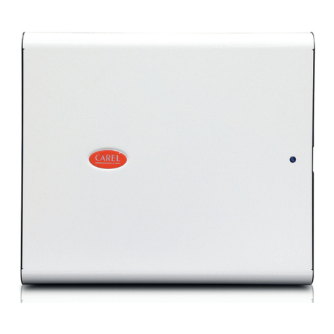
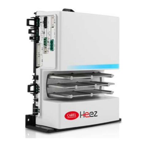
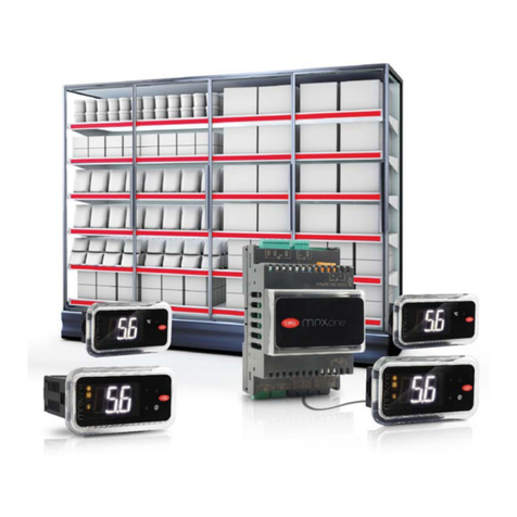
Carel MasterCella Split User manual

MasterCella Split
Manuale d’uso
User manual
LEGGI E CONSERVA
QUESTE ISTRUZIONI
READ AND SAVE
THESE INSTRUCTIONS


Vogliamo farvi risparmiare tempo
e denaro!
Vi assicuriamo che la completa lettura
di questo manuale vi garantirà una
corretta installazione ed un sicuro
utilizzo del prodotto descritto.
AVVERTENZE IMPORTANTI
PRIMA DI INSTALLARE O INTERVENIRE
SULL’APPARECCHIO, LEGGERE ATTENTAMENTE E
SEGUIRE LE ISTRUZIONI CONTENUTE IN QUESTO
MANUALE.
Questa apparecchiatura è stata costruita per
funzionare senza rischi per gli scopi prefissati
purché:
• l’installazione, la conduzione e la manutenzione siano
eseguite secondo le istruzioni contenute in questo
manuale;
• le condizioni dell’ambiente e della tensione di
alimentazione rientrino tra quelle specificate.
Ogni utilizzo diverso da questo e l’apporto di
modifiche, non espressamente autorizzate dal
costruttore, sono da intendersi impropri.
La responsabilità di lesioni o danni causati da uso
improprio ricadrà esclusivamente sull’utilizzatore.
Si osservi che questa macchina contiene componenti
elettrici sotto tensione e quindi tutte le operazioni di
servizio o manutenzione devono essere condotte da
personale esperto e qualificato, cosciente delle
necessarie precauzioni.
Prima di accedere alle parti interne sezionare la
macchina dalla rete elettrica.
Smaltimento delle parti del controllore
Il controllore è composto da parti in metallo e da parti in
plastica.Tutte queste parti vanno smaltite secondo le
Normative locali in materia di smaltimento.
Pulizia del controllore
Utilizzare esclusivamente detergenti neutri ed acqua.
We wish to save you time and money!
We can assure you that a thorough
reading of this manual will guarantee
correct installation and safe use of the
product described.
IMPORTANT
BEFORE INSTALLING OR OPERATING ON THE
DEVICE, CAREFULLY READ THE INSTRUCTIONS IN
THIS MANUAL.
This instrument has been designed to operate without
risks only if:
• installation, operation and maintenance are performed
according to the instructions of this manual;
• environmental conditions and supply voltage fall within
the values indicated here below.
Any different use or changes which have not been
previously authorised by the manufacturer, are
considered improper.
Responsibility for injures or damage caused by
improper use will fall exclusively on the user.
Warning: voltage is present in some electrical
components of this instrument, thus all the service
or maintenance operations must be performed by
expert and skilled personnel only, aware of the
necessary precautions to be taken.
Before accessing the internal parts, disconnect the
power supply.
Disposing of the parts of the controller
The controller is made from metal parts and plastic parts.
All these parts should be disposed of according to local
standards on waste disposal.
Cleaning the controller
Only use neutral detergents and water.
LEGGI E CONSERVA
QUESTE ISTRUZIONI
READ AND SAVE
THESE INSTRUCTIONS


Indice:
1. Architettura Hardwre MTSB boar - MST terminal (485) 3
1.1 Significato degli ingressi ed uscite 3
1.2 Terminale MTST 5
2. Architettura Hardware 7
2.1 Significato degli ingressi ed uscite 7
2.2 Terminale PST 8
3. Descrizione dei parametri di configurazione 9
3.1 Classificazione dei parametri 9
3.2 Parametri di rilievo per le unità 11
3.3 Parametri relativi allo sbrinamento 11
3.4 Tabella rissuntiva dei parametri da verificare
durante l’installazione 11
4. Riconfigurazione di un controllo con i parametri
di fabbrica (default) 12
4.1 Funzionalità offerte ai sistemi di supervisione
su seriale RS485 13
5. Funzioni HACCP 13
5.1 Caratteristiche generali 13
5.2 Gestione allarmi HACCP 13
5.3 Cancellazione degli allarmi 15
5.4 Impostazione dei principali parametri di lavoro 15
6. Descrizione dei parametri di configurazione 15
6.1 /= parametri relativi alla gestione delle sonde di temperatura 15
6.2 A = parametri per la gestione degli allarmi 17
6.3 c = parametri per la gestione del compressore 22
6.4 d = parametri per la gestione dello sbrinamento 25
6.5 F = parametri per la gestione delle ventole dell’evaporatore 28
6.6 H = altre predisposizioni 29
6.7 L = parametri gestione sensore luce 31
6.8 r = parametri relativi alla regolazione della temperatura 32
6.9 T = parametri regolatore 34
6.10 Stato di ON/OFF del MCS 35
7. Segnalazioni luminose 36
7.1 Codici e segnalazioni di allarme 37
7.2 Avvertenze 37
8. Ricerca ed eliminazione dei problemi 38
9. Accessori 40
9.1 Chiave per la copia parametri 40
9.2 Adattatore seriale per rete RS485 41
10. CARATTERISTICHE TECNICHE 42
10.1 MTSB* 42
10.2 Terminale MTST 44
10.3 Treminale PST 45
10.4 Adattatore seriale RS485 45
11. DIMENSIONI 46
Contents:
1. Hardware structure MTSB board - MST terminal (485) 3
1.1 Meaning of the inputs and outputs 3
1.2 MTST terminal 5
2. Hardware structure 7
2.1 Meaning of the inputs and outputs 7
2.2 PST terminal 8
3. Description of the configuration parameters 9
3.1 Classification of the parameters 9
3.2 Parameters valid for units 11
3.3 Defrost parameters 11
3.4 Summary of the parameters to be checked
during installation 11
4. Reconfiguring a controller with the default
parameters 12
4.1 Functions available to RS485 serial supervisory
systems 13
5. HACCP functions 13
5.1 General characteristics 13
5.2 HACCP alarm management 13
5.3 Deleting the alarms 15
5.4 Setting the main operating parameters 15
6. Setting the main configuration parameters 15
6.1 /= temperature probe management parameters 15
6.2 A = alarm management parameters 17
6.3 c = compressor management parameters 22
6.4 d = defrost management parameters 25
6.5 F = evaporator fan management parameters 28
6.6 H = other settings 29
6.7 L = light sensor management parameters 31
6.8 r = temperature control parameters 32
6.9 T = controller parameters 34
6.10 MCS ON/OFF mode 35
7. LED signals 36
7.1 Codes and alarm signals 37
7.2 Warnings 37
8. Troubleshooting 38
9. Accessories 40
9.1 Key for copying the parameters 40
9.2 Serial adaptor for RS485 network 41
10. TECHNICAL SPECIFICATIONS 43
10.1 MTSB* 43
10.2 MTST terminal 44
10.3 PST terminal 45
10.4 Serial adaptor RS485 45
11. DIMENSIONS 46


1. Architettura Hardware
MTSB board - MTST terminal (485) MTSB000100
1.1 Significato degli ingressi ed uscite
I morsetti 18, 19 e 20 non sono utilizzati (NC)
1.1.1 Alimentazione
• Ingresso alimentazione da rete su tre morsetti a vite con capacità
di corrente 30A max
• tensione di alimentazione a seconda del modello 230 Vac - 115 Vac -
24 Vac 50/60 Hz
• utilizzo con cavi di sezione da 0,5 a 4 mm2(cavo flessibile)
• Morsetti faston di appoggio per connessione carichi: 6 morsetti per
L, N e Terra.
Morsetto L: Linea (250 Vac max 30A max)
Morsetto N: Neutro (250 Vac max 30A max)
Morsetto : Terra (30 A max)
Faston L (x6): Linea morsetti faston (16 A max per contatto)
Faston N (x6): Neutro morsetti faston (16 A max per contatto)
Faston (x6): Terra morsetti faston (16 A max per contatto)
1.1.2 Uscite relè
• contatti relè isolati con morsetti faston (6,3 mm) capacità di corrente
16 A max;
• isolamenti principale tra contatti di relè diversi, disconnessione ridotta
sul contatto relè;
• utilizzo con contatti faston femmina (6,3 mm) con cavi da 1,5 a 2,5 mm2;
• cablaggio connessioni mediante i faston di alimentazione con ponti
(cavo 2,5 mm2con terminazioni faston femmina lunghezza 10-15 cm)
uno per ogni uscita.
Nota: numerazione come da serigrafia su Circuito Stampato.
1. HARDWARE STRUCTURE
MTSB board - MST terminal (485) MTSB000100
1.1 Meaning of the inputs and outputs
Terminals 18, 19 and 20 are not used (NC)
1.1.1 Power supply
• Mains power supply connection using three screw terminals, with
max current rating 30 A
• power supply voltage according to the model: 230 Vac - 115 Vac -
24 Vac 50/60 Hz
• cable cross-sections from 0.5 to 4 mm
2
(flexible cables)
• aston terminals for connecting the loads: 6 terminals for L, N
and Earth.
Terminal L: Line (250Vac max 30 A max)
Terminal N: Neutral (250Vac max 30 A max)
Terminal : Earth (30A max)
Faston L (x6): Line terminals faston (16 A max per contact)
Faston N (x6): Neutral terminals faston (16 A max per contact)
Faston (x6): Earth terminals faston (16 A max per contact)
1.1.2 Relay outputs
• insulated relay contacts with faston terminals (6.3 mm), max. current
rating 16 A
• primary insulation main between the contacts of different relays
• connect to female faston contacts (6.3 mm), with wires from 1.5 to
2.5 mm
2
.
• wiring connections using the power supply fastons with jumpers
(2.5 mm
2
wires with female faston terminals, length 10-15 cm), one
for each output.
Note: the numbering refers to the silk-screening on the PCB.
3MasterCella Split - cod. +030221396 rel. 1.2 - 03.12.2004
Connessioni interne di
alimentazione consigliate
Suggested inside
power connections
RS 485
optional board
RS485
Connection to
Supervisor
Cavo di connessione RS485 AWG20/AWG22
a 2 fili a coppia ritorta schermato
RS485 cable connection AWG20/AWG22
with 2 paired twisted and shielded wires
T Products
NC
NC
NC
GND
RX/TX+
RX/TX-
GND (Shield)
TX/RX
TX/RX
GND (Shield)
TX/RX
TX/RX
T Defrost
T Ambient
Digital Input 1
Digital Input 2
Photo Res.
15 16 17 18 19 20 21 22 23 24 25 26 27 28 29 30 31 32 33 34 35
PROG.
KEY
non utilizzare
don't use it
L
N
Power Supply
115/230 Vac (depending on the model - 30A max)
MTSB board
-10T50
Comp.DefrostFanAlarm AUX 2
AUX
AUX 1
Lux
AUX
up-to
100m
1
2
35 4
6
7
8
9
1012 11
13
14
12 3 13 1412
VL GND
RS-485
MTST Terminale/Terminal
230/24Vac 4VA
15 16 1718 19
ID1 ID2
Input digitali
programmabili
digital input
programmable
Sonda
ambiente
ambient
probe
Dip-Switch
1234
ON
OFF
12A, 12FLA
72LRA*
250Vac
4A, 2FLA
12LRA
250Vac
4A, 2FLA
12LRA
250Vac
4A, 2FLA
12LRA
250Vac
12A, 12FLA
72LRA*
250Vac
12A RES.
250Vac
Fig. 1.1.1
(*) T OFF minimo tra due start motore deve essere maggiore di 60 s.
(*) T OFF minimum between two following motor load starting is 60 s or more.

Faston 1: C relè compressore (250 Vac 16 A 2 Hp max )
Faston 2: NO relè compressore
Faston 3: C relè defrost (250 Vac 16 A res. max)
Faston 4: NC relè defrost
Faston 5: NO relè defrost
Faston 6: C relè aux2/antiapp. (250 Vac 10 A res. (2 A) max)
Faston 7: NO relè aux2/antiapp.
Faston 8: C relè ventilatori (250 Vac 10 A res. (2 A) max)
Faston 9: NO relè ventilatori
Faston 13: C relè aux1/luce (250 Vac 16 A res. 500 W-1000 VA max)
Faston 14: NO relè aux1/luce
Faston 10: C relè allarme (250 Vac 10 A res. (2 A) max)
Faston 11: NC relè allarme
Faston 12: NO relè allarme
1.1.3 Ingressi sonde NTC
• ingressi di misura per sonde NTC standard CAREL (10 Kohm a 25 ˚C);
• compatibilità con misura PLUG IN, misura -50T90 ˚C;
• filtro ingresso 1 mS (disturbi veloci, burst), la misura è filtrata da SW
con media (/2 da 0,1 a 2 s circa);
• connessione con morsetti fissi a vite per cavo da 0,5 a 1,5 mm2;
• distanza max 30 m, per compatibilità normative (surge).
Morsetti 24/25: ingresso segnale NTC sonda regolazione (ambiente)
(-50T90 ˚C)
Morsetto 26/27: ingresso segnale NTC sonda defrost (-50T90 ˚C)
Morsetto 28/29: ing. segnale NTC sonda prodotto/defrost2 (-50T90 ˚C)
1.1.4 Ingressi digitali
• ingressi da contatto pulito (non alimentato) con corrente di chiusura
8-12 mA;
• filtro ingresso 1 mS (disturbi veloci, burst), il segnale è filtrato da SW
media a 240 mS;
• connessione con morsetti fissi a vite per filo da 0,5 a 1,5 mm2;
• distanza max 30 m, per compatibilità normative (surge).
Morsetto 30: riferimento ingresso digitale 1
Morsetto 31: ingresso digitale 1
Morsetto 32: riferimento ingresso digitale 2
Morsetto 33: ingresso digitale 2
Nota: l'utilizzo degli ingressi è programmabile da parametri (ingresso
multifunzione)
1.1.5 Ingresso sensore presenza luce
• ingressi da fotoresistenza per segnalare l'apertura delle porte in
armadi refrigerati, uno o due sensori previsti;
• connessione a morsetti a vite fissi (2 vie) sez. cavo da 0,5 a 1,5 mm2;
• Distanza massima 30 metri.
Morsetto 34/35: ingresso fotoresistenza (presenza luce)
Nota: È disponibile un solo ingresso con la possibilità di collegare uno
o due sensori in parallelo
1.1.6 Connessione a terminale MTST
• velocità seriale prevista: 4800 o 19200 bit/S.
• connessione a tre fili con cavo AWG20/22, distanza max 100 m.
Per connessione RS485 utilizzare cavi con sezione adeguata alla
distanza.
Morsetto 20: NC
Morsetto 21: riferimento alimentazione GND
Morsetto 22: segnale Tx/Rx -
Morsetto 23: segnale Tx/Rx +
Faston 1: C compressor relay (250 Vac 16 A 2 HP max)
Faston 2: NO compressor relay
Faston 3: C defrost relay (250 Vac 16 A res. max)
Faston 4: NC defrost relay
Faston 5: NO defrost relay
Faston 6: C aux2/demist relay (250 Vac 10 A res. (2 A) max)
Faston 7: NO aux2/demist relay
Faston 8: C fan relay (250 Vac 10 A res. (2 A) max)
Faston 9: NO fan relay
Faston 13: C aux1/light relay (250 Vac 16 A res. 500 W-1000 VA max)
Faston 14: NO aux1/light relay
Faston 10: C alarm relay (250 Vac 10 A res. (2 A) max)
Faston 11: NC alarm relay
Faston 12: NO alarm relay
1.1.3 NTC probe inputs
• measurement inputs for standard CAREL NTC probes (10 Kohm at 25 ˚C);
• compatibility with PLUG IN measurements, measuring -50T90 ˚C;
• 1 mS input filter (fast disturbance, burst), the measurement is filtered
by SW using the average (/2 from around 0.1 a 2 s);
• connection with fixed screw terminals for wires from 0.5 to 1.5 mm
2
;
• distance max 30m for standards compliance (surge).
Terminal 24/25: NTC control probe (ambient) input signal (-50T90 ˚C )
Terminal 26/27: NTC defrost probe input signal (-50T90 ˚C )
Terminal 28/29: NTC product/defrost2 probe input signal (-50T90 ˚C )
1.1.4 Digital inputs
• inputs from free contacts (not supplied) with closing current of
8-12 mA;
• 1 mS input filter (fast disturbance, burst), the signal is filtered by SW
using the average at 240 mS;
• connection with fixed screw terminals for wires from 0.5 to 1.5 mm
2
;
• distance max 30 m for standards compliance (surge).
Terminal 30: digital input 1 reference
Terminal 31: digital input 1
Terminal 32: digital input 2 reference
Terminal 33: digital input 2
Note: The use of the inputs can be programmed by setting the
corresponding parameters (multi-function inputs)
1.1.5 Light presence sensor inputs
• inputs from photocell to signal the opening of the doors on
refrigerated display cabinets, one or two sensors featured;
• connection with fixed screw terminals (2-way) for wire cross-sections
from 0.5 to 1.5 mm
2
;
• Maximum distance 30 metres.
Terminal 34/35: photocell input (light presence)
Note: One input only is available, with the possibility of connecting one
or two sensors in parallel
1.1.6 Terminal connection
• serial speed 4800 bit/S or 19200 bit/S.
• three-wire connection using AWG20/22 cable, max distance 10 m.
For the RS485 connection use cables (power supply) with a suitable
cross-section for the distance.
Terminal 20: NC
Terminal 21: power supply GND
Terminal 22: Tx/Rx - signal
Terminal 23: Tx/Rx + signal
4MasterCella Split - cod. +030221396 rel. 1.2 - 03.12.2004

1.1.7 Connettore opzione seriale RS485
• connettore opzionale per collegamento scheda con driver RS485 per
interfaccia supervisore
• pin-strip 8 vie con fissaggio scheda mediante asole (saldabile a CS)
per scheda opzione seriale
• velocità seriale prevista 9600-19200 bit/S
• connessione a 3 morsetti a vite fissi (GND, Tx/Rx+, Tx/Rx-)
Morsetto 15: segnale Tx/Rx - (RS485)
Morsetto 16: segnale Tx/Rx + (RS485)
Morsetto 17: riferimento segnale GND
1.1.8 Connettore chiave programmazione
• connessione per chiave di copia parametri con alimentazione diretta
5 Vdc (max 30 mA)
• funzionamento con controllo spento, alimentato da chiave.
• interfaccia seriale di tipo i2c bus con connessione diretta a
microprocessore e memoria interna (non utilizzabile per altre
connessioni).
• connettore a 4 vie standard PLUG IN con segnali: +5 V, GND, I2Clk,
I2Dat.
1.2 Terminale MTST
I terminali elettronici MTST sono stati progettati per essere utilizzati
con i controlli MTSB CAREL mettendo a disposizione le funzioni di
interfaccia operatore. Tali funzioni sono: visualizzazione numerica,
interfaccia utente con tastiera e dispositivo per programmazione con
telecomando. Inoltre, sono provvisti di: ingresso sonda di temperatura,
2 ingressi digitali e buzzer.
1.2.1 Installazione e collegamenti
Avvertenze generali - ambienti di destinazione e collegamenti
Le seguenti condizioni soddisfano una corretta installazione:
1. evitare il montaggio dello strumento negli ambienti che presentano:
ampie e rapide fluttuazioni della temperatura ambiente, umidità
relativa maggiore dell’80%, esposizione a getti d’acqua diretti
sotto pressione, alte interferenze elettromagnetiche e/o
radiofrequenze (per es. di antenne trasmittenti);
2. utilizzare capicorda adatti ai morsetti in uso. Allentare ciascuna vite
ed inserirvi i capicorda, quindi serrare le viti.
Ad operazione ultimata tirare leggermente i cavi per verificarne il
corretto serraggio;
3. separare quanto più possibile i cavi delle sonde e degli ingressi
digitali dai cavi dei carichi induttivi e di potenza per evitare possibili
disturbi elettromagnetici. Non inserire mai nelle stesse canaline
(comprese quelle dei cavi elettrici) cavi di potenza e cavi delle
sonde. Evitare che i cavi delle sonde siano installati nelle immediate
vicinanze di dispositivi di potenza (contattori, interruttori
magnetotermici o simili);
4. ridurre il più possibile il percorso dei cavi dei sensori ed evitare che
compiano percorsi a spirale, racchiudendo dispositivi di potenza.
Per prolungare i cavi delle sonde, usare cavi con sezione minima di
almeno 0,5 mm2;
5. i cavi di collegamento devono garantire l’isolamento fino a 90 °C;
Sicurezza per gli operatori e precauzioni nel maneggiare la/e
scheda/e
Per tutelare la sicurezza degli operatori e la salvaguardia della scheda,
prima di effettuare qualsiasi intervento sulla scheda togliere l’alimenta-
zione dalla stessa. I danneggiamenti elettrici che si verificano sui com-
ponenti elettronici avvengono quasi sempre a causa delle scariche
elettrostatiche indotte dall’operatore. È quindi necessario prendere ade-
guati accorgimenti per queste categorie di componenti, ed in particolare:
• prima di maneggiare qualsiasi componente elettronico o scheda,
toccare una messa a terra (il fatto stesso di evitare di toccare non è
sufficiente in quanto una scarica di 10.000 V, tensione molto facile da
raggiungere con l’elettricità statica, innesca un arco di circa 1 cm);
1.1.7 RS485 serial connector option
• optional connector for card with RS485 driver for supervisor interface
• 8-way pin-strip with slotted card for serial option
• serial speed 9600-19200 bit/S
• connection by 3 fixed screw terminals (GND, Tx/Rx+, Tx/Rx-)
Terminal 15: Tx/Rx - signal (RS485)
Terminal 16: Tx/Rx + signal (RS485)
Terminal 17: signal GND
1.1.8 Programming key connector
• connector for the key used to copy the parameters, with direct 5 Vdc
power supply (max 30 mA)
• operation when the controller is off, powered by the key
• i2c-bus serial interface with direct connection to the microprocessor
and internal memory (cannot be used for other connections).
• standard 4-way PLUG IN connector with the following signals: +5 V,
GND, I2Clk, I2Dat.
1.2 MTST terminal
The electronic MTST terminals have been designed to be used with
MTSB CAREL’s controllers putting at your disposal the operator
interface functions. These functions are: numerical display, user interface
with keypad and a device for programming with remote control.
Moreover, they are supplied with: temperature probe input, 2 digital
inputs and buzzer.
1.2.1 Installation and connections
General warnings – installation and connection environments
The following conditions represent the correct installation:
1. avoid installing the instrument in environments featuring: wide and
rapid fluctuations in ambient temperature, relative humidity over
80%, exposure to direct jets of pressurised water, high levels
of electromagnetic and/or radio-frequency interference
(e.g. transmitting antennae);
2. use cable terminals that are suitable for the terminals being used.
Loosen each screw and insert the cable ends, then tighten the
screws. Once this operation has been completed, lightly tug the
cables to check that they are sufficiently tight;
3. separate as much as possible the probe and digital input cables
from cables carrying inductive loads and power cables, to avoid any
electromagnetic disturbance. Never lay power cables and
probe cables in the same channels (including those for the electrical
cables). Do not install the probe cables in the immediate vicinity of
power devices (contactors, thermal overload switches or the like);
4. reduce the path of the sensor cables as much as possible and avoid
laying spiral paths around power devices. To extend the probe
cables, use cables with a minimum cross-section of at least
0.5 mm
2
;
5. connection cables should be suitable for 90 °C operation;
Advertency. Safety information
Before any servicing on the card disconnect power supply from the
card in order to safeguard the personnel against injury and the card
itself against damages.
Electrical damage on electronic components usually occurs because of
electrostatic discharges caused by the operator.
Therefore, when handling these components, you must refer to the
following:
• before using any electronic component or card, touch a grounding (it
is not sufficient not to touch, because a 10 000V discharge, a very
easy voltage value to reach with static electricity, produces an
electric arc of about 1 cm);
5MasterCella Split - cod. +030221396 rel. 1.2 - 03.12.2004
• i materiali devono rimanere per quanto possibile all’interno delle loro
confezioni originali. Se è necessario prelevare la scheda base da una
confezione trasferire il prodotto in un imballo antistatico senza
toccare il resto della scheda con le mani;
• evitare nel modo più assoluto di utilizzare sacchetti di plastica,
polistirolo o spugne non antistatiche e il passaggio diretto tra
operatori (per evitare fenomeni di induzione elettrostatica e
conseguenti scariche).
1.2.2 Installazione a pannello
Con riferimento alle Fig. 1.2.2.1
e 1.2.2.2 e relativi particolari:
1. praticare nel pannello un foro
di dimensioni 182x153 mm;
2. svitare le due viti frontali
(partt. a, b di Fig. 1.2.2.1) ed
estrarre lo sportello (part. c);
3. svitare le due viti (partt. d,
e), che tengono uniti
coperchio inferiore e frontale
del terminale MTST e quindi
separare le due parti;
4. inserire sul frontale il kit
MTSTKIT000 (guarnizione
sovrapposta a quella interna
+ pannello metallico);
5. praticare nella parte poste
riore due fori (Fig. 1.2.2.2
partt. f, g);
6. unire la parte posteriore e il
frontale, con il pannello nel
mezzo, fissando il tutto con
le due viti (dimensioni 4x20*
mm) contenute nel kit.
* lunghezza max 20 mm.
Avvertenza: è necessario rimuovere i due denti superiori di fissaggio
(part. h) della parte frontale prima dell’inserimento a pannello. Praticare
il foro sulla parte superiore (part. i) o inferiore (part. l) del retro per il
passaggio dei cavi. Il passo delle filettature previste varia da PG9
(diametro 16 mm) a PG21 (diametro 29 mm). È consigliabile usare un
trapano o una fresa per facilitare l’operazione di foratura. Collegare i fili
alla morsettiera. Riavvitare le viti (partt. d, e), quindi, richiudere lo
sportello (part. c).
Indicazioni di funzionamento sulla tastiera e comandi
su tasto
1segnalaz. e reset per HACCP (LED rosso); tasto premuto
per 5 s;
2segnalaz. e attivaz. LUCE; tasto premuto per 1 s;
3segnalazione e attivazione ON/OFF se abilitato L0; tasto
premuto per 5 s;
4segnalaz. e attivaz. AUX; tasto premuto per 1 s;
5segnalaz. e attivaz. CICLO-CONTINUO; tasto premuto
per 5 s;
6segnalaz. COMPRESSORE ON;
7segnalaz. e attivaz. DEFROST; tasto premuto per 5 s;
8segnalaz. e tacitazione ALLARME.
Lo stato di lampeggio indica una richiesta di attuazione
non eseguibile fino allo scadere delle temporizzazioni che
lo ritardano.
I tasti 6, 7e 8sono utilizzati anche per le funzioni di
visualizzazione ed impostazione parametri.
• the components must be kept inside their original package as long as
possible. If necessary, take the main board from a package and put it
into an antistatic package without touching the back of the board with
your hands;
• absolutely avoid non-antistatic plastic bags or sponge and
polystyrene and do not hand in the card directly to other among
operators (to avoid any electrostatic induction and discharges).
1.2.2 Panel installation
In reference to Fig. 1.2.2.1 and
1.2.2.2 and the corresponding parts:
1. Make a hole in the panel with the
following dimens.: 182x153mm.
2. Unscrew the two frontal screws
(Fig. 1.2.2.1, a, b) and take out
the central door (part c).
3. Unscrew the two screws (parts
d, e) that keep the lower and
frontal cover of the MTST
terminal connected and separate
the two parts.
4. Insert on the front panel the kit
MTSTKIT000 (gasket on top of
the internal gasket + metallic panel).
5. Make two holes in the back
part (Fig. 1.2.2.2 in the perforated
part - parts f, g).
6. Join the back part and the front,
with the panel in between, and
fix the whole unit with the two
screws (dimensions: 4x20*mm)
that are contained in the kit.
* max length 20 mm.
Warning: the two upper fastening teeth (part h) must be removed from
the front panel before inserting the unit in the panel. Make the hole on
the upper (part i) or lower part (part l) of the rear for the passage of the
cables. The step of the thread can vary from PG9 (diameter 16 mm) to
PG21 (diameter 29 mm). A drill or miller should be used to assist the
drilling operation. Connect the wires to the terminal block. Retighten the
screws (parts d, e), then close the door (part c).
Indication on the display and button commands
1HACCP signal and reset (red LED); button pressed for
5 s;
2LIGHT signal and activation; button pressed for 5 s;
3signal and ON/OFF activation if L0 enabled; button pressed
for 5 seconds
4AUX signal and activation; button pressed for 1 s;
5CONTINUOUS-CYCLE signal and activation; button
pressed for 5 s;
6compressor ON signal;
7DEFROST signal and activation; button pressed for 5 s;
8ALARM signal and silencing.
The blinking status means that the corresponding function
is delayed by a timed routine.
The buttons 6, 7and 8are used for the display and
parameter set functions.
6MasterCella Split - cod. +030221396 rel. 1.2 - 03.12.2004
1
5
6
2 4
87
3
2 4 8
35
67
Fig. 1.2.2.2
ab
c
de
h
i
l
Fig. 1.2.2.1

1.2.3 Installazione a parete
Con riferimento alle Fig. 1.2.3.1 e relativi particolari:
1. svitare le due viti frontali (partt.
a, b di Fig. 1) ed estrarre lo
sportello (part. c).
2. svitare le due viti (partt. d, e) che
tengono uniti coperchio inferiore
e frontale del terminale MTST e
quindi separare le due parti.
3. dopo aver scelto dove far
passare la canalina o i cavi (da
sopra o da sotto) e aver
praticato gli opportuni fori
(partt. i, l) per pressacavi o
pressatubi, praticare i tre fori
(partt. m, n, o) sia nel guscio
posteriore del terminale MTST
che in corrispondenza della
parete stessa.
4. inserire i tasselli a muro, contenuti nel kit, nei fori effettuati nella
parete, quindi, fissare la parte posteriore del terminale MTST con le
tre viti (partt. m, n, o) e i relativi O-Ring alla parete stessa.
5. fissare i pressacavi o pressatubi prima di montare la parte frontale
del terminale MTST.
6. montare la parte frontale prestando attenzione al posizionamento
dei denti superiori (part. h) e al corretto fissaggio delle 2 viti (partt. d,
e) (non stringere esageratamente per non deformare la plastica).
7. dopo aver collegato i fili alla morsettiera del terminale MTST,
richiudere lo sportello (part. c).
2. Architettura Hardware - MTSB board - PST
Large terminal (TTL) MTSB000110
2.1 Significato degli ingressi ed uscite
I morsetti 18 e 19 non sono utilizzati (NC)
1.2.3 Wall-mounted installation
With reference to Fig. 1.2.3.1:
1. Unscrew the two frontal screws
(Fig. 1, parts a, b) and remove
the central door (part c).
2. Unscrew the two screws (parts d,
e) that keep the lower and frontal
cover of the MTST terminal
connected and separate the two
parts.
3. Once having decided where to
pass the cable duct or the cables
(from above or from below) and
having made the proper holes (in
the part drilled in advance - parts
i, l) for cablepresses and
pipepresses, make three holes
(parts m, n, o) both in the MTST
terminal and in the wall itself.
4. Insert the wall-nugs, contained in the kit, into the holes made in the
wall and then fix the back part of the MTST terminal with the three
screws (parts m, n, o) and the relevant O-Rings to the wall itself.
5. Fix the cablepresses or pipepresses before mounting the frontal part
of the MTST terminal.
6. Mount the frontal part, being careful with the positioning of the upper
teeth (part h) and the proper fixing of the two screws (parts d, e) (do
not press excessively in order to avoid plastic deformation).
7. After connecting the cables to the terminal block, shut the door (part c).
2. HARDWARE STRUCTURE - MTCSB board - PST
Large terminal (TTL) MTSB000110
2.1 Meaning of the inputs and outputs
Terminals 18 and 19 are not used (NC)
7MasterCella Split - cod. +030221396 rel. 1.2 - 03.12.2004
parte inferiore
lower part
i
l
parte superiore
upper part
parte posteriore
back side
100
190
160
fg
mn
o
120
65
Fig. 1.2.3.1
Connessioni interne di alimentazione consigliate
Suggested inside power connections
16A 2HP10A10A16A
RS 485
optional board
RS485
Connection to
Supervisor
T Products
NC
NC
GND
RX/TX+
RX/TX-
T Defrost
T Ambient
Digital Input 1
Digital Input 2
Photo Res.
15 16 17 18 19 20 21 22 23 24 25 26 27 28 29 30 31 32 33 34 35
PROG.
KEY
L
N
Power Supply
230 Vac (30A max)
10A
MTSB board
-10T50
Comp.DefrostFanAlarm AUX 2
AUX
AUX 1
Lux
AUX
1
2
35 4
6
7
8
9
1012 11
13
14
PST Large
Terminale/Terminal
PSTCONXXXX
TO I/O
BOARD
up-to
10m
Power (green)
GND (brown)
RX/TX (white)
GND (yellow)
(12Vdc)
(24Vdc)
1
2
3
Fig. 2.1.1

2.1.1 Alimentazione
Vedi steso paragrafo relativo a “MTST terminal (485)”.
2.1.2 Uscite relè
Vedi steso paragrafo relativo a “MTST terminal (485)”.
2.1.3 Ingressi sonde NTC
Vedi steso paragrafo relativo a “MTST terminal (485)”.
2.1.4 Ingressi digitali
Vedi steso paragrafo relativo a “MTST terminal (485)”.
2.1.5 Ingressi sensori presenza luce
Vedi steso paragrafo relativo a “MTST terminal (485)”.
2.1.6 Connessione a terminale PST Large
• connessione con alimentazione del terminale PST "Large" PSTxxL
• alimentazione da tensione livellata 20…35Vdc (0,7 W max 50 mA)
protetta da PTC fuse 100…140 mA
• velocità seriale prevista 4800 bit/S
• connessione a quattro fili con cavo AWG28, distanza max 10 m
Morsetto 20: alimentazione terminale +VL (8…35 Vdc)
Morsetto 21: riferimento alimentazione GND
Morsetto 22: segnale Tx/Rx (intf. transistor, livelli TTL)
Morsetto 23: riferimento GND
2.1.7 Connettore opzione seriale RS485
Vedi steso paragrafo relativo a “MTST terminal (485)”.
2.1.8 Connettore chiave programmazione
Vedi steso paragrafo relativo a “MTST terminal (485)”.
2.2 Terminale PST
I terminali elettronici PST sono stati progettati per essere utilizzati con i
controllori MTSB CAREL mettendo a disposizione le funzioni di
interfaccia operatore. Tali funzioni sono: visualizzazione numerica,
interfaccia utente con tastiera e dispositivo per programmazione con
telecomando. Inoltre sono provvisti di: ingresso sonda di temperatura, 2
ingressi digitali e buzzer.
2.2.1 Installazione PST Large
Per il fissaggio a pannello si
devono utilizzare n. 2 viti a testa
svasata con diametro filetto
max 3,9 mm.
• Eseguire tutti i collegamenti
elettrici necessari.
• Inserire lo strumento nel foro
a pannello facendo rientrare i
cavi collegati e controllare che
la guarnizione sia posizionata
correttamente. Mantenere il
frontale in posizione
premendo centralmente.
Avvitare le due viti laterali fino
al bloccaggio del frontale. Non
stringere troppo per evitare di
comprimere eccessivamente
la guarnizione.
• Applicare la placchetta frontale.
2.1.1 Power supply
See the paragraph on the “MTST terminal (485)”.
2.1.2 Relay outputs
See the paragraph on the “MTST terminal (485)”.
2.1.3 NTC probe inputs
See the paragraph on the “MTST terminal (485)”.
2.1.4 Digital inputs
See the paragraph on the “MTST terminal (485)”.
2.1.5 Light presence sensor inputs
See the paragraph on the “MTST terminal (485)”.
2.1.6 PST Large terminal connection
• connection with power supply for the PST "Small" and PSTxxL
"Large" terminals
• 20 to 35 Vdc “clamped” voltage power supply (0.7 W max 50 mA)
protected by 100 to 140 mA PTC fuse
• serial speed 4800 bit/S
• four-wire connection using AWG28 cable, max distance 10 m
Terminal 20: terminal power supply +VL (8…35 Vdc)
Terminal 21: power supply GND
Terminal 22: Tx/Rx signal
Terminal 23: GND
2.1.7 RS485 serial connector option
See the paragraph on the “MTST terminal (485)”.
2.1.8 Programming key connector
See the paragraph on the “MTST terminal (485)”.
2.2 PST terminal
The electronic PST terminals have been designed to be used with
MTSB CAREL’s controllers putting at your disposal the operator
interface functions. These functions are: numerical display, user
interface with keypad and a device for programming with remote
control. Moreover, they are supplied with: temperature probe input, 2
digital inputs and buzzer.
2.2.1 PST Large installation
For the panel fastening, two
flaring head screws must be
used with a major diameter of
max. 3,9 mm.
• Carry out all the necessary
electrical connections.
• Insert the instrument in the
panel hole and make the
connected cables return to
their place and check that
the gasket is placed correctly.
Keep the front in its position
pressing it in the middle.
Screw the two side screws
until the front is fastened.
Don’t fasten too much to
avoid compressing the gasket
excessively.
• Put the front plate.
8MasterCella Split - cod. +030221396 rel. 1.2 - 03.12.2004
NON ECCEDERE
NEL SERRAGGIO
DON’T TIGHTEN
TOO MUCH
21 3
Fig. 2.2.1.1

Indicazioni di funzionamento sulla tastiera e comandi su tasto
1segnalaz. e reset per HACCP (LED rosso);
tasto premuto per 5 s;
2segnalaz. e attivaz. LUCE; tasto premuto per 1 s;
3segnalaz. e attivaz. ON/OFF; tasto premuto per 5 s;
4segnalaz. e attivaz. AUX; tasto premuto per 1 s;
5segnalaz. e attivaz. CICLO-CONTINUO; tasto
premuto per 5 s;
6segnalaz. COMPRESSORE ON;
7segnal. e attivaz. DEFROST; tasto premuto per 5 s;
8segnalaz. e tacitazione ALLARME.
Lo stato di lampeggio indica una richiesta di attuazione
non eseguibile fino allo scadere delle temporizzazioni che lo ritardano.
I tasti 6, 7e 8sono utilizzati anche per le funzioni di visualizzazione ed
impostazione parametri.
3. Descrizione dei parametri di configurazione
3.1 Classificazione dei parametri
I parametri, oltre che divisi in relazione al TIPO, sono raggruppati in
categorie logiche individuate dalle lettere iniziali dei parametri stessi. Di
seguito vengono riportate le categorie esistenti con significato e lettere
identificatrici.
Famiglia Descrizione
St set point
/ parametri relativi alla gestione della sonda di temperatura
A parametri relativi alla gestione degli allarmi
c parametri relativi alla gestione del compressore
d parametri relativi allo gestione dello sbrinamento
F parametri relativi alla gestione dei ventilatori di
evaporazione
H parametri generali di configurazione
L parametri relativi alla luce / gestione ON/OFF / altri
r parametri relativi alla regolazione di temperatura
I / S parametri configurazione LAN
t parametri relativi alla gestione eventi orologio / HACCP
3.1.1 Modifica
Gli strumenti della serie MCS sono gestiti da un microprocessore che
permette di adattare il funzionamento del controllore alle effettive
esigenze di regolazione, e, a tale scopo, sono previsti opportuni
parametri di funzionamento, raggruppati in due livelli:
• parametri di uso frequente (indicati con la lettera F);
• parametri di configurazione (indicati con la lettera C).
La selezione di questi ultimi è protetta da un opportuno codice
(PASSWORD), per impedire manomissioni indesiderate.
I parametri sono modificabili da tastiera frontale e, nel caso siano
previste le opportune opzioni, da seriale.
3.1.2 Modifica del set point
Sullo strumento è impostato un set point di 4 °C ma può essere
modificato come segue:
• premendo per 1 s compare a display St;
• premendo si visualizza il valore e per incrementare o diminuire
il valore con e/o fino a raggiungere il valore desiderato;
• premendo nuovamente si registra il valore e viene visualizzata
la temperatura letta.
Indication on the display and button commands
1HACCP signal and reset (red LED); button pressed
for 5 s;
2LIGHT signal and activation; button pressed for 5 s;
3ON/OFF signal and activation; button pressed for 5 s;
4AUX signal and activation; button pressed for 1 s;
5CONTINUOUS-CYCLE signal and activation; button
pressed for 5 s;
6compressor ON signal;
7DEFROST signal and activation; button pressed
for 5 s;
8ALARM signal and silencing.
The blinking status means that the corresponding function is delayed
by a timed routine.
The buttons 6, 7, 8are used for the display and parameter set functions.
3. Description of the configuration parameters
3.1 Classification of the parameters
The parameters, as well as being divided by TYPE, are also grouped
into logical categories identified by the fist letters of the parameters
themselves. Following is a list of the existing categories, with the
meaning and identifying letters.
Family Description
St set point
/ temperature probe management parameters
A alarm management parameters
c compressor management parameters
d defrost management parameters
F evaporator fan management parameters
H general configuration parameters
L light / ON/OFF management / other parameters
r temperature control management parameters
I / S LAN configuration parameters
t clock / HACCP event management parameters
3.1.1 Modification
The MCS series instruments are managed by a microprocessor that
adapts the operation of the controller to the effective requirements.
For this purpose, a number of operating parameters are available and
have been grouped into two levels:
• frequently-used parameters (indicated by the letter F);
• configuration parameters (indicated by the letter C).
The latter are protected by a special code (PASSWORD) to prevent
unwanted tampering.
The parameters can be modified from the front keypad and, where the
required options are featured, via a serial connection.
3.1.2 Modifying the set point
The instrument features a set point of 4 °C, however this value can be
modified as follows:
• press for 1 s to display the value of the St, flashing;
• pressing displays the value, then increase or decrease the
value with and/or until reaching the desired value;
• press again to save the value and display the temperature
read.
9MasterCella Split - cod. +030221396 rel. 1.2 - 03.12.2004
12 4 6 8
35 7
Fig. 2.2.1.2

3.1.3 Modifica dei parametri di tipo "F"
• premendo per 5 s (in caso d’allarme, tacitare prima il buzzer,
se previsto) a display compare il codice del primo parametro
password;
• scorrere i parametri con e/o fino a raggiungere il
parametro di cui si vuole modificare il valore;
• premere per visualizzarne il valore associato;
• incrementare o diminuire il valore con e/o fino a
raggiungere il valore desiderato;
• confermare temporaneamente con ;
• ripetere le operazioni per gli altri parametri da modificare;
• per memorizzare definitivamente le modifiche apportate premere
per 5 s.
3.1.4 Modifica dei parametri di tipo “C”
• premendo per 5 s (in caso d’allarme, tacitare prima il buzzer,
se previsto) a display compare il codice del primo parametro password;
• premendo nuovamente compare 00;
• con o impostare 22 (password);
• confermando con compare il codice del primo parametro
modificabile (si vedono tutti i parametri "F" e "C")
• scorrere i parametri con e/o fino a raggiungere il
parametro di cui si vuole modificare il valore;
• premere per visualizzarne il valore associato;
• incrementare o diminuire il valore con e/o fino a
raggiungere il valore desiderato;
• confermare temporaneamente con ;
• ripetere le operazioni per gli altri parametri da modificare;
• per memorizzare definitivamente le modifiche apportate premere
per 5 s.
AVVERTENZA importante: durante la procedura di modifica parametri
solo premendo per 5 s si passa dalla memorizzazione
temporanea delle modifiche a quella definitiva. Se, quindi, viene tolta
tensione allo strumento prima della pressione di TUTTE le
modifiche realizzate e temporaneamente memorizzate vengono perse.
Per la completa memorizzazione è inoltre necessario che il controllo
rimanga alimentato per altri 60 s (timeout).
3.1.5 Uscita dalla procedura senza modifica dei parametri:
Per uscire dalla procedura senza modificare i parametri non premere
nessun tasto per almeno 60 s (uscita per TIMEOUT).
In questo modo lo strumento ritorna al funzionamento normale.
3.1.3 Modifying the type "F parameters"
• press for 5 s (in the event of an alarm, first mute the buzzer, if
featured) to display the code of the first modifiable password
parameter;
• scroll the parameters with and/or until reaching the
parameter to be modified;
• press to display the associated value;
• increase or decrease the value with and/or until reaching
the desired value;
• temporarily confirm by pressing ;
• repeat the operations for the other parameters to be modified;
• to definitively save the modifications made press for 5 s.
3.1.4 Modifying type “C parameters”
• press for 5 s (in the event of an alarm, first mute the
buzzer, if featured) to display the code of the first modifiable
parameter (PS);
• press again, 00 is displayed;
• press to set 22 (password);
• confirm with , the code of the first modifiable parameter is
displayed (see the "F" and "C" parameters)
• scroll the parameters with and/or until reaching the
parameter to be modified;
• press to display the associated value;
• increase or decrease the value with and/or until reaching
the desired value;
• temporarily confirm by pressing ;
• repeat the operations for the other parameters to be modified;
• to definitively save the modifications made press for 5 s.
Important warning: during the parameter modification procedure only
pressing for 5 s will definitively save the modifications.
Consequently, if the instrument is switched off before pressing
ALL the modifications made and temporarily saved will be lost.
To definitively save the changes the controller must be powered for a
further 60 s (timeout).
4.1.5 Exiting the procedure without saving the changes:
To exit the procedure without saving the changes to the parameters,
do not press any button for at least 60 s (exit by timeout).
In this way the instrument returns to normal operation.
10 MasterCella Split - cod. +030221396 rel. 1.2 - 03.12.2004
3.2 Parametri di rilievo per le unità
Gli strumenti possono essere programmati per rilevare sia l'allarme di
alta che di bassa temperatura.
Gli allarmi comportano l’attivazione del cicalino interno, se previsto, e
la visualizzazione di un codice sul display: HI per l'alta temperatura e
LO per la bassa.
Le condizioni che generano l'allarme di temperatura sono:
• allarme di alta temperatura: la temperatura rilevata dalla sonda
ambiente è sopra il punto di lavoro impostato per un valore maggiore
di AH (temperatura ambiente > set point +AH);
• allarme di bassa temperatura: la temperatura rilevata dalla sonda
ambiente è sotto il punto di lavoro impostato per un valore maggiore
di AL (temperatura ambiente < set point -AL).
In base alla programmazione di default si ha AL e AH= 0 (allarmi non
abilitati) e l'eventuale segnalazione di allarme è ritardata di 120 minuti
(Ad=120). Con uno o entrambi gli allarmi abilitatati (valore > 0, es: 4) il
valore associato ad “Ad” indica i minuti di ritardo che il controllo deve
attendere prima di generare un allarme di temperatura. Ovviamente se
durante il ritardo programmato le condizioni di temperatura ritornano
regolari (ovvero entro i ±4 gradi attorno al punto di lavoro impostato) non
si genererà alcun allarme, e si resetterà il conteggio dei minuti di ritardo.
NOTA: durante l'installazione può succedere che, entro i 120 minuti di
ritardo previsti, l'unità non si porti nell'intervallo di ±4 gradi attorno al
set point impostato, per cui si attiva l'allarme di temperatura. In tale
caso si suggerisce di aumentare il ritardo modificando il parametro Ad.
3.3 Parametri relativi allo sbrinamento
Se lo strumento è utilizzato per la gestione dello sbrinamento è
necessario controllare alcuni parametri prima di procedere con
l'avviamento. Verificare i parametri di seguito indicati (per la descrizione
completa riferirsi alla sezione relativa del manuale):
• dI: Intervallo tra gli sbrinamenti (senza RTC o senza orari programmati)
• dP: Durata massima sbrinamento
• d0: Tipo di sbrinamento
• dt: set point temperatura di fine sbrinamento.
3.4 Tabella riassuntiva dei parametri da verificare durante
l’installazione
3.2 Parameters valid for units
The instruments can be programmed to detect both high and low
temperature alarms. The alarms turn on the internal buzzer, if fitted,
and show a code on the display: HI for the high temperature alarm and
LO for the low temperature alarm.
The following conditions cause a temperature alarm:
• high temperature alarm: the temperature measured by the ambient
probe is above the set point by a value greater than AH (room
temperature > set point +AH);
• low temperature alarm: the temperature measured by the ambient
probe is below the set point by a value greater than AL (room
temperature < set point -AL).
Using the default values, AL and AH= 0 (alarms not enabled) and any
alarm signal is delayed by 120 minutes (Ad= 120). When one or both
the alarms are enabled (value > 0, e.g.: 4 ), the value of “Ad” indicates
the delay in minutes that the controller waits before signalling a
temperature alarm. Obviously, if during the set delay the temperature
conditions return within the limits (that is, within the ±4 degrees around
the set point), no alarm will be generated, and the delay counting will
be reset.
NOTE: during installation the unit might not reach the interval of ±4
degrees around the set point within the 120 minute delay time, and
therefore the temperature alarm will be activated. In this case it is
recommended to increase the delay by modifying the parameter Ad.
3.3 Defrost parameters
If the instrument is used for defrost management, a number of
parameters need to be checked before commissioning.
Check the following parameters (for a complete description, see the
corresponding section of the manual):
• dI: Interval between defrosts (without RTC or without set times)
• dP: Maximum defrost duration
• d0: Type of defrost
• dt: end defrost temperature set point.
3.4 Summary of the parameters to be checked during
installation
11 MasterCella Split - cod. +030221396 rel. 1.2 - 03.12.2004
codice parametro Tipo Min Max U.M. Def
PARAMETRI LAN
H0 indirizzo su seriale C 1 199 - 1
PARAMETRI REGOLATORE
rd Differenziale regolatore F 0.1 +19.9 °C/°F 2
PARAMETRI SBRINAMENTO
d0 Tipo di sbrinamento (0= resistenza, 1= gas caldo) C 0 3 flag 0
dI Intervallo tra gli sbrinamenti F 0 199 ore 8
dt Set point temperatura di fine sbrinamento F -40 +199 °C/°F 4
PARAMETRI DI ALLARME
Ad Ritardo allarme di temperatura C 0 +199 min 120
PARAMETRI VENTOLE
F4 relè fan usato per le ventole o come ausiliario C 0 2 - 0
ALTRE PREDISPOSIZIONI
H1 configurazione relè ausiliario n.1 C 0 7 - 5
H2 configurazione relè ausiliario n.2 (nelle unità a 6 relè) C 0 7 - 6
ORARI DI SBRINAMENTO
¯t1 giorno del primo evento di defrost C 0 10 0
-t1 ora del primo orario di defrost settabile C 0 24 ore 0
_t1 minuto del primo orario di defrost settabile C 0 59 min 0
...
¯t4 giorno del quarto evento di defrost C 0 10 0
-t4 ora del quarto orario di defrost settabile C 0 24 ore 0
_t4 minuto del quarto orario di defrost settabile C 0 59 min 0

4. Riconfigurazione di un controllo con i
parametri di fabbrica (default)
In situazioni di funzionamento molto particolari (forti disturbi impulsivi di
origine elettromagnetica) può accadere che lo strumento rilevi errori
nella memorizzazione interna dei dati, compromettendo il corretto
funzionamento dello strumento. Nel caso il microprocessore individui
un errore nella memorizzazione dei dati, viene visualizzato sul display
la seguente sigla:
EA
Per ripristinare il corretto funzionamento è necessario seguire una
procedura particolare detta di RESET.
Questa procedura è assolutamente eccezionale, come lo sono le
cause che la possono richiedere, e permette quasi sempre di ripristina-
re il corretto funzionamento. È comunque buona regola indagare sulle
cause che hanno generato questo tipo di errore, in modo da evitarne il
ripetersi. In particolare si invita a leggere con attenzione il capitolo
“Installazione” ed il paragrafo “Avvertenze” del presente manuale.
Quando l'errore EA si presenta con frequenza si suggerisce comunque
di far verificare il controllo in quanto potrebbe non essere garantita la
precisione originaria.
Per resettare il controllo, procedere nel seguente modo:
• togliere tensione allo strumento;
• premendo contemporaneamente i tasti e , ridare tensione
• a display si vedrà l’indicazione “– 3”, a questo punto rilasciare i tasti
• ricaricata la configurazione di fabbrica, lo strumento esegue
automaticamente un riavvio.
Nota importante: la procedura di RESET ripristina lo strumento
assegnando ai parametri il valore previsto in fabbrica (detto valore di
Default), perdendo, quindi tutte le modifiche eventualmente apportate
ai parametri di lavoro.
Vista la delicatezza della manovra, la procedura di reset deve essere
eseguita da personale specializzato, tenendo presente che non
danneggia lo strumento bensì lo riporta alla configurazione con cui è
stato prodotto. Se, quindi, si sono modificati i parametri di funzionamento
in modo disordinato, al punto da perdere il controllo del regolatore, si
può resettare il controllo per riportarsi alla configurazione iniziale.
4. Reconfiguring a controller with the default
parameters
In specific operating situations (strong electromagnetic disturbance),
the instrument may show errors when saving the data, compromising
the correct operation of the instrument. If the microprocessor identifies
an error in the saving of the data, the display shows the following
code:
EA
To restore correct operation, a RESET procedure needs to be
performed.
This procedure must only be performed in exceptional circumstances,
as the possible causes are also exceptional, almost always allows
correct operation to be restored. It is in any case good practice to seek
the cause of this type of error, so as to prevent it from being repeated.
In particular, carefully read the chapter on “Installation” and the para-
graph “Warnings” of this manual.
If the error EA occurs frequently, the controller should be checked, as
the specified precision may not be guaranteed.
To reset the controller, proceed as follows:
• switch the instrument off;
• press the and buttons at the same time, switch on again
• the display will show “– 3”, then release the buttons
• once the default configuration has been loaded, the instrument is
automatically rebooted
Important note: the RESET procedure resets the instrument by
setting the parameters to the default values, any modifications made
to the operating parameters will thus be lost.
Given the delicacy of this operation, the procedure must be performed
by specialist personnel, not damage the instrument, but rather resets
its original configuration when purchased. Therefore, if the operating
parameters have been modified in a disorganised fashion, to the point
where the controller is unworkable, it can be reset to its original
configuration.
12 MasterCella Split - cod. +030221396 rel. 1.2 - 03.12.2004
code parameter Type Min Max UOM Def
LAN PARAMETERS
H0 Serial address (for the Slaves) C 1 199 - 1
CONTROLLER PARAMETERS
rd Control differential F 0.1 +19.9 °C/°F 2
DEFROST PARAMETERS
d0 Type of defrost (0= electric heater, 1= hot gas) C 0 3 flag 0
dI Interval between defrosts F 0 199 hours 8
dt End defrost temperature set point F -40 +199 °C/°F 4
ALARM PARAMETERS
Ad Temperature alarm delay C 0 +199 mins 120
FAN PARAMETERS
F4 fan relay used for the fans or as an auxiliary C 0 2 - 0
OTHER SETTINGS
H1 configuration of auxiliary relay no. 1 C 0 7 - 0
H2 configuration of auxiliary relay no. 2 (in the units with 6 relays) C 0 7 - 0
DEFROST TIMES (only for the Master with RTC)
¯t1 day of the first defrost event C 0 10 0
-t1 hours of the first settable defrost time C 0 24 hours 0
_t1 minutes of the first settable defrost time C 0 59 mins 0
...
¯t4 day of the first defrost event C 0 10 0
-t4 hours of the xth settable defrost time C 0 24 hours 0
_t4 minutes of the first settable defrost time C 0 59 mins 0

Alcune eventuali personalizzazioni vengono cancellate, H1, H2, A4, A5,
ecc., e vanno, quindi, ripristinate. Inoltre è possibile perdere eventuali
personalizzazioni applicate ai livelli di visibilità per ripristinare i quali è
sufficiente usare una chiave di copia opportunamente programmata.
4.1 Funzionalità offerte ai sistemi di supervisione su seriale
RS485
Le unità di controllo della serie MasterCella Split possono
agevolmente essere integrate in ampie reti facenti capo a sistemi di
supervisione mediante l’uso dell’interfaccia seriale RS485 opzionale.
L’architettura del software sui MasterCella Split, fornisce ai sistemi
di supervisione delle primitive di servizio che consentono di effettuare
quanto segue da una stazione remota di monitoraggio e
controllo (un PC):
• Monitoraggio delle temperature rilevate dalle tre sonde, sullo stato
degli ingressi digitali e degli allarmi;
• Lettura e modifica del valore dei parametri;
• Azione a distanza sugli attuatori del controllo (relè luci e/o ausiliari);
• Defrost dell’unità in due modalità: solo start, start/stop sincronizzati;
vedi parametro d2.
• Da unità di Supervisione è possibile mandare in OFF un MCS.
5. Funzioni HACCP
5.1 Caratteristiche generali
La funzione di HACCP permette il controllo della temperatura con la
registrazione di situazioni d’allarme per il superamento di soglie
massime di temperatura e con durate significative.
Tali eventi possono derivare sia da anomalie di funzionamento della
macchina controllata come da mancanze di alimentazione. Le funzioni
di controllo aggiuntive sono pensate come aiuto per gli utilizzatori per il
monitoraggio della temperatura di conservazione dei cibi orientata all’a-
dempimento delle fasi di verifica e registrazione richieste dalla normati-
va HACCP per la garanzia di corretta conservazione dei cibi.
5.2 Gestione allarmi HACCP
Il controllo prevede la gestione di due diversi eventi che possono
risultare pericolosi per la corretta conservazione degli alimenti:
1. allarme HA: se la temperatura di regolazione é superiore ad un
valore massimo per un tempo maggiore ad un tempo di ritardo
impostato. Il valore di soglia corrisponde al valore impostato sullo
strumento per l’allarme di alta temperatura (SET + AH); il tempo di
ritardo corrisponde alla somma dei tempi impostati con due
parametri: parametro Ad e tr;
2. allarme HF: mancanza di alimentazione per un tempo prolungato
(maggiore di un minuto) con valore di temperatura, al ritorno
tensione, superiore al valore massimo previsto (SET + AH).
In entrambi i casi viene rilevato un allarme con segnalazione sul
display del codice d’allarme, accensione del LED di retroilluminazione
del tasto HACCP e attivazione del relè d’allarme o buzzer se presenti.
Viene inoltre eseguita una registrazione dello stato d’allarme che può
essere successivamente visualizzata. Dal momento che la
registrazione riporta esclusivamente il giorno della settimana e l’ora (e
non la data completa), il riconoscimento dell’errore e la lettura della
registrazione stessa ha senso nell’arco di una settimana dal verificarsi
dell’evento per non ingenerare equivoci sulla localizzazione temporale
dell’evento stesso.
Eventuali errori non cancellati, saranno ripresentati ad ogni mancanza
di alimentazione e sino a cancellazione, l’errore potrà anche essere
cumulativo ovvero verrà ricordato che esiste sia un errore HF che un
errore HA non cancellato, ed è l’unico caso nel quale vengono
visualizzati entrambi.
Some custom settings are deleted, e.g. H1, H2, A4, A5, etc., and
should thus be reset.
If any custom settings involving the levels of visibility (C or F) have
been lost, to reset them use a suitably programmed hardware key.
4.1 Functions available to RS485 serial supervisory
systems
The MasterCella Split series control units can easily be integrated into
large networks connected to a supervisory system using the optional
RS485 serial interface (which can be used as an alternative to the
LAN).
The structure of the MasterCella Split software provides the
supervisory system service primitives that allow the following functions
to be performed from a remote monitoring and control station (PC):
• Monitoring of the temperature measured by the three probes, of the
status of the digital inputs and of the alarms;
• Reading and modification of the values of the parameters;
• Remote control of the actuators (light and/or auxiliary relays);
• Defrosting. In two modes only: synchronised start, start/stop, see
parameter d2;
• A MCS can be switched OFF from the Supervisor.
5 HACCP functions
5.1 General characteristics
The HACCP functions expand the temperature control operation by
adding the recording of alarm situations due to the exceeding of the
maximum temperature thresholds for significant periods, which may
derive either from operating anomalies in the controlled machines or
from power failures. The added control functions are designed to help
the user monitor the food storage temperature in order to comply with
the checking and recording phases required by the HACCP standards
on correct food storage.
5.2 HACCP alarm management
The controller features the management of two different events that
may be dangerous for correct food storage:
1. HA alarm: if the control temperature is higher than a maximum
value for a longer than a set delay time. The threshold value
corresponds to the value set on the instrument for the high
temperature alarm (SET + AH), the delay time corresponds to the
sum of the times set for two parameters: parameter Ad and tr;
2. HF alarm: power failure for an extended period (greater than one
minute) with the temperature at power resumption higher than the
maximum value (SET + AH).
In both cases an alarm is generated, with the alarm code shown on the
display, the lighting up of the LED on the HACCP button and the
activation of the alarm relay or buzzer, if present. Furthermore, the
status of the alarm is recorded, and can subsequently be displayed.
As the saving of the event only describes the day of the week and the
time (and not the complete date), the identification of the error and the
reading of the event only makes sense within a week of the occurrence
of the event.
Any errors that are not deleted will be restored after each power failure,
and until deleted the error is also cumulative, that is, the HF error and
the HA errors that have not been deleted are signalled, the only case
in which both are displayed.
13 MasterCella Split - cod. +030221396 rel. 1.2 - 03.12.2004

5.2.1 Modalità di funzionamento e segnalazione degli allarmi
Nello stato di abilitazione della rilevazione degli allarmi con i parametri
AH e tr correttamente impostati, si esegue un controllo continuo con
cadenza ogni minuto del valore della temperatura di regolazione.
Si considerano, inoltre, anche altri parametri (soglia d’allarme e tempi
di ritardo) e si effettua la segnalazione e memorizzazione dell’allarme
di tipo HA, che riguarda le condizioni di superamento dei limiti impostati
di temperatura protratti per durate superiori ai tempi di ritardo impostati.
Lo strumento adempie anche al controllo della temperatura alla ripartenza
dopo le situazioni di mancanza d’alimentazione, con la segnalazione e
memorizzazione degli allarmi di tipo HF.
Con il parametro Ad si imposta il ritardo allarmi dello strumento, al
superamento di tale tempo si ha una segnalazione d’allarme (alta
temperatura) generata dallo strumento stesso; tale segnalazione può
essere utilizzata come preallarme per la successiva segnalazione di
superamento del tempo totale (Ad + tr) che determina l’allarme HA
vero e proprio.
I due parametri permettono di impostare una durata massima di 398
minuti.
Una eventuale situazione d’allarme della sonda di regolazione dello
strumento (rE) viene considerata equivalente alla situazione di
temperatura maggiore della soglia e, quindi, determina anche la
segnalazione di un allarme HA dopo il tempo di ritardo impostato.
Il riconoscimento di un allarme HF comporta la registrazione delle
seguenti informazioni nei parametri di stato:
1. giorno della settimana dell’evento;
2. ora della mancanza di alimentazione;
Nel caso di più eventi successivi d’allarme (HF), le informazioni relative
all’allarme vengono aggiornate, mentre l’ora ed il giorno sono quelli
dell’ultimo evento.
Il riconoscimento di un allarme HA
comporta la registrazione delle
seguenti informazione nei parametri di
stato:
1. giorno della settimana dell’evento;
2. ora iniziale (e minuti) dell’evento
d’allarme;
computo del tempo totale dell’allarme
HA. Se non resettato il tempo totale è
pari a tempo allarme 1 + tempo
allarme 2 + tempo allarme
NOTA BENE: Fine allarme HA, non significa che sparisce la
visualizzazione, ma solamente il punto dove viene fermato il conteggio
dei minuti dell’allarme. L’indicazione HA/HF scompare solo per volontà
dell’utente che deve cancellare l’allarme.
Gli allarmi HA e HF se non resettati vengono comunicati subito ad ogni
accensione della macchina. Il tempo totale dell’allarme HA viene
mantenuto durante le mancanze di corrente ma non incrementato.
5.2.2 Visualizzazione degli allarmi
La segnalazione del riconoscimento di uno dei due eventi d’allarme
previsti HA ed HF viene attuata mediante il tasto HACCP del Terminale
e con il comando delle attuazioni d’allarme disponibli sullo strumento:
LED di retro illumunazione tasto HACCP d’allarme, buzzer disponibile,
relè d’allarme se disponibile.
Allarme HA: si accende stabilmente il tasto HACCP.
Se presenti si attivano anche buzzer e relè d’allarme.
Allarme HF: si accende lampeggiando il tasto HACCP.
Se presenti si attivano anche buzzer e relè d’allarme.
Se il LED del tasto HACCP è acceso, premendo il tasto relativo verrà
visualizzata per circa 3 s la durata in minuti dell’allarme HA, dopodichè
si tornerà alla normale visualizzazione.
Per accedere agli altri dati seguire la procedura descritta nel paragrafo
3 “Accesso e modifica parametri” ed entrare poi ai campi di Tab. 6.9.1.
5.2.1 Operating mode and alarm signals
When the detection of the alarms has been enabled by the correct
setting of parameters AH and tr, the instrument performs continuous
control, at one minute intervals, of the control temperature.
Some other parameters are taken into consideration as well (alarm
threshold and delay times) and type HA alarm signalling and recording
are made, which regard the exceeding of the set temperature limits for
extended periods longer than the set delay times. The instrument also
controls the temperature on re-starts after power failures, signalling
and recording type HF alarms.
The parameter Ad sets the alarm delay of the instrument, on exceeding
this time an alarm signal (high temperature) is activated, generated by
the instrument; this signal can be used as a pre-alarm for the subse-
quent signal that the total time has been exceeded (Ad + tr), which
determines the actual HA alarm.
The two parameters allow a maximum duration of 398 minutes to be
set.
Any alarm event involving the control probe of the instrument (rE) is
considered equivalent to the temperature being greater than the
threshold, and thus also determines an HA alarm signal after the set
delay time.
Wen the HF alarm is detected, the following information on the status
arameters is recorded:
1. weekday of the event;
2. time of the power failure;
In the case of a series of alarm (HF) events, the information on the
alarm is updated with the time and the day of the most recent event.
When the HA alarm is detected,
the following information on the
status parameters is recorded:
1. the weekday of the event;
2. the starting hours (and minutes)
of the alarm event;
estimate of the total time of the HA
alarm. If not reset, the total time is
equal to *alarm time 1 + *alarm
time 2 + *alarm time
NOTE: The end of the HA alarm does not refer to when the signal is no
longer displayed, but rather represents the point at which the count of
the number of minutes of the alarm is stopped. The HA/HF signal only
disappears when the user deletes the alarm. If not reset, the HA and
HF alarms are signalled immediately each time the machine is started.
The total time of the HA alarm is maintained during the power failures,
but not increased.
5.2.2 Alarm signals
The detection of one of the two alarm events, HA or HF, is signalled by
the HACCP button on the terminal, and by the activation of any alarm
devices available on the instrument: HACCP alarm button LED, buzzer
if featured, alarm relay if featured.
HA alarm: the HACCP button is on steady.
If present, the buzzer and the alarm relay are also activated.
HF alarm: the HACCP button flashes.
Display of the total duration of the HACCP alarm.
If the LED on the HACCP button is on, pressing the button displays the
duration of the HA alarm in minutes, for around 3 seconds, after which
the normal display will return.
To access the other data, follow the procedure described in paragraph
3 “Accessing and modifying the parameters” and enter the fields shown
in Table 6.9.1
14 MasterCella Split - cod. +030221396 rel. 1.2 - 03.12.2004
temperatura
temperature
AH
AO
Set Point
HI HI
HA
HA
fine allarme HA
alarm HA end
fine allarme HA
alarm HA end
tempo
time
Ad tr Ad tr
tempo allarme 1
alarm 1 time
tempo allarme 2
alarm 2 time
Fig. 5.2.1.1

5.3 Cancellazione degli allarmi
In caso di segnalazione di un allarme HA o HF é possibile eseguire un
reset delle segnalazioni oppure cancellare completamente le
segnalazioni e la registrazione dello stato:
1. con la pressione del tasto HACCP per 5 s si ottiene la
completa cancellazione dell’allarme memorizzato andando così a
resettare anche il led di retroilluminazione del tasto (ovvero si
cancellano le variabili di registrazione di stato). La stessa funzione
è attuabile mediante l’azzeramento del parametro “t0”.
2. per eseguire la tacitazione del buzzer e la disattivazione del relè
d’allarme, se presenti, bisogna premere SET.
Rimangono visualizzate sul display il codice d’allarme HA o HF e la
segnalazione tramite accensione led del tasto HACCP
Avvertenza: Il reset delle segnalazioni HACCP non comporta la
cancellazione di altri allarmi attivi nello strumento.
5.4 Impostazione dei principali parametri di lavoro
Nella fase di installazione i principali parametri da controllare sono di
seguito elencati. In particolare é da tenere presente che due parametri
determinano la abilitazione o disabilitazione della rilevazione degli
allarmi HACCP: AH e tr.
AH: Soglia d’allarme di alta temperatura
tr: tempo di ritardo di rilevazione allarmi HACCP
to: reset degli allarmi (o tasto per i terminali large).
6. Descrizione dei parametri di configurazione
6.1 / = parametri relativi alla gestione delle sonde di
temperatura
/ PARAMETRI Tipo Min Max U.M. Def.
/2 stabilità misura C 1 15 - 4
/4 sonda virtuale C 0 100 - 0
/5 selezione °C o °F C 0 1 - 0
/6 punto decimale C 0 1 - 0
/8 calibrazione sonda 3 C 0 ±19.9 ˚C/˚F 0
/9 defrost con sonda 3 C 0 1 - 0
/A esistenza sonde S2 ed S3 C 0 3 - 2
/C calibrazione sonda 1 C 0 ±19.9 ˚C/˚F 0
/d calibrazione sonda 2 C 0 ±19.9 ˚C/˚F 0
/P abilitazione uso sonda terminale C 0 1 - 0
/t configurazione terminale C 0 4 - 4
Tab. 6.1.1
/2: Stabilità misura
Definisce il coefficiente usato per stabilizzare la misura di temperatura.
Valori bassi assegnati a questo parametro offrono una risposta pronta
del sensore alle variazioni di temperatura; la lettura diventa però
maggiormente sensibile ai disturbi. Valori alti, invece, rallentano la
risposta ma garantiscono una maggiore immunità ai disturbi, ovvero
una lettura più stabile.
- Def: 4
/4: Sonda virtuale
Definisce una sonda fittizia, non fisicamente esistente, utilizzata nella
normale attività di regolazione. Tale parametro determina i pesi di una
media ponderata con cui si calcola il valore della sonda virtuale di
regolazione in base alla lettura della sonda ambiente (S1) e della
sonda S3 (punto caldo del banco). La formula è la seguente:
sonda virtuale = [100 - (“/4”)]xS1 + (“/4”)xS3 ;
100
5.3 Deleting the alarms
In the event of the HA or HF alarm signal, the signals can be reset,
both the signals and the recording of the status can be deleted
completely:
1. press the HACCP button for 5 seconds to completely delete the
alarm saved and switch off the LED on the button (that is, delete the
variables that record the status). The same function can be
performed by resetting the parameter “t0”.
2. to silence the buzzer and deactivate the alarm relay, if present,
press SET. The alarm code, HA or HF, will still be displayed and
the LED on the HACCP button will be on steady or flashing.
Warning: Resetting the HACCP signals does not delete any other
active alarms on the instrument.
5.4 Setting the main operating parameters
The main parameters to be checked during installation are listed below.
Specific attention is drawn to the two parameters that enable or disable
the signalling of the HACCP alarms: AH and tr.
AH: High temperature alarm threshold
tr: HACCP alarm delay time
to: alarm reset (or button on the large terminals).
6 Setting the main configuration parameters
6.1 / = temperature probe management parameters
/ PARAMETERS Type Min Max UOM Def.
/2 measurement stability C 1 15 - 4
/4 virtual probe C 0 100 - 0
/5 °C or °F selection C 0 1 - 0
/6 decimal point C 0 1 - 0
/8 probe 3 calibration C 0 ±19.9 ˚C/˚F 0
/9 defrost with probe 3 C 0 1 - 0
/A existence of probes S2 and S3 C 0 3 - 2
/C probe 1 calibration C 0 ±19.9 ˚C/˚F 0
/d probe 2 calibration C 0 ±19.9 ˚C/˚F 0
/P enable terminal probe C 0 1 - 0
/t terminal configuration C 0 4 - 4
Table 6.1.1
/2: Measurement stability
Defines the coefficient used to establish the temperature measurement.
Low values assigned to this parameter offer the prompt response of the
sensor to variations in temperature; the reading is however more
sensitive to disturbance. High values slow down the response but
guarantee greater immunity to disturbance, that is, a more stable and
more precise reading.
- Def : 4
/4: Virtual probe
Defines a fictitious probe, which does not physically exist, used in the
normal control operations. This parameter determines the average
pondered weight used to calculate the value of the virtual probe, based
to the reading of the ambient probe (S1) and probe S3 (showcase hot
point). The formula is the following:
virtual probe = [100 -(“/4”]xS1 + (“/4”)xS3 ;
100
15 MasterCella Split - cod. +030221396 rel. 1.2 - 03.12.2004

Con il valore 0 la sonda virtuale coincide con la sonda 1; con il valore
100 la sonda virtuale coincide con la sonda 3.
In caso di rottura (cortocircuito o sconnessione) di una delle due sonde
(S1 o S3) la regolazione si sposta automaticamente sull’altra sonda,
segnalando l’allarme relativo alla sonda rotta, se la sonda è presente e
se /4 è diverso da 0 e da 100.
- Def : 0
/5: Selezione °C o °F
Definisce l'unità di misura usata.
0= gradi Centigradi;
1= gradi Fahrenheit.
Passando da un’unita di misura all'altra “in corso d’opera” vengono
automaticamente convertiti i valori letti dalle sonde e, quindi,
visualizzati correttamente. Anche i valori delle sonde inviati al sistema
di supervisione vengono convertiti in base a questo parametro. NON
cambiano invece i valori impostati precedentemente per il set point e il
differenziale del regolatore.
Nota bene: Questi ultimi, assieme a tutti i parametri di temperatura,
devono essere aggiornati manualmente.
- Def : 0
/6: Punto decimale
Consente di abilitare o disabilitare la visualizzazione della temperatura
con la risoluzione al decimo di grado tra -9.9 e 99.9 nel terminale
piccolo (3 digit), nel terminale grande (4 digit) da -99.9 a 999.9.
0= i dati sono visualizzati con il decimo di grado .
1= i dati sono visualizzati al grado
- Def : 0
/C, /d, /8: Calibrazione o Offset di taratura
Questi parametri permettono di correggere le misure dei tre ingressi
sonda. Il valore assegnato a questo parametro viene infatti aggiunto
(valore positivo) o tolto (valore negativo) alla temperatura rilevata dalla
sonda. Ad es., se si vuole diminuire la temperatura visualizzata di 2.3
gradi bisogna settare /C= -2.3.
- Def : 0
/9: Defrost con sonda 3
Tale parametro consente di eseguire un defrost utilizzando
congiuntamente entrambe le sonde S2 ed S3 se settato ad 1. In tal
caso il defrost in temperatura termina quando la temperatura rilevata
da entrambe le sonde è maggiore o uguale a quella impostata quale
temperatura di fine sbrinamento (parametro “dt”). È, pertanto, possibile
usare la sonda 3 quale sonda di defrost su un secondo evaporatore.
- Def : 0
/A: Esistenza sonde S2 ed S3 (defrost e punto caldo)
Il valore di tale parametro informa lo strumento sul fatto che ad esso
siano o meno collegate le sonde di defrost (S2) e/o del punto caldo del
banco (S3). I valori possibili di tale parametro sono i seguenti:
0= sonda di defrost e sonda 3 assenti
1= sonda di defrost assente e sonda 3 presente
2= sonda di defrost presente e sonda 3 assente
3= sonda di defrost e sonda 3 entrambe presenti
- Def : 2
NB: Se si programma /A=0 o /A=3 verrà impostato automaticamente il
parametro /4=0.
Esempi:
I) Nel caso non sia presente la sonda S2 porre “/A= 0 o 1”: Lo strumento
sarà così informato del fatto che in fase di pre-installazione non è
stata cablata la sonda S2 e non darà segnalazione di errore.
II) Nel caso non sia presente la sonda S3, porre “/A= 0 o 2 ”: ciò eviterà
la segnalazione dell’errore relativo a questa sonda.
With a value of 0, the virtual probe coincides with probe 1; with a value
of 100 the virtual probe coincides with probe 3.
In the event of faults (short-circuit or disconnection) on one the two
probes (S1 or S3), the control automatically shifts to the other probe,
signalling the alarm relating the faulty probe, if the probe is present
and if /4 is not 0 or 100.
- Def : 0
/5: °C or °F selection
Defines the unit of measure used.
0= degrees Centigrade;
1= degrees Fahrenheit.
When changing from one unit of measure to the other when in
operation, the values read by the probes are automatically converted
and displayed correctly. The values read by the probes sent to the
supervisory system are also converted according to this parameter. On
the other hand, the previously set values of the set point and
differential are NOT converted.
Note: All the temperature parameters must be updated manually.
- Def : 0
/6: Decimal point
Enables or disables the display of the temperature with resolution to a
tenth of a degree, between -9.9 and 99.9, on the small terminal (3
digits), and from -99.9 a 999.9 on the large terminal (4 digits).
0= the data is displayed to the tenth of a degree.
1= the data is displayed to the degree
- Def : 0
/C, /d, /8: Calibration or Offset
These parameters allow the temperatures measured by the three
probes to be corrected. The values assigned to these parameters are in
fact added to (positive value) or subtracted from (negative value) the
temperature measured by the probe. For example, if the temperature
displayed needs to be decreased by 2.3 degrees, set /C= -2.3.
- Def : 0
/9: Defrost with probe 3
This parameter allows a defrost to be performed using both probes S2
and S3, if set to 1. In this case, the temperature-based defrost ends
when the temperature measured by both the probes is greater than or
equal to the set end defrost temperature (parameter “dt”). Therefore,
probe 3 can be used as a defrost probe on a second evaporator.
- Def : 0
/A: Presence of probes S2 and S3 (defrost and hot point)
The value of this parameter tells the instrument whether the defrost
probe (S2) and/or the showcase hot point probe (S3) are connected.
The following values are allowed for this parameter:
0= defrost probe and third probe absent
1= defrost probe absent and probe 3 present
2= defrost probe present and probe 3 absent
3= defrost probe and probe 3 both present
- Def : 2
Note: If /A=0 or /A=3, the parameter /4 will be automatically be set
to 0.
Examples:
I) If probe S2 is not present, set “/A= 0” or 1”: The instrument will thus
know that probe S” has not been wired in the pre-installation phase,
and will not give an error signal.
II) If probe S3 is not present, set “/A= 0” or 2”: this will prevent the
error signal relating to this probe.
16 MasterCella Split - cod. +030221396 rel. 1.2 - 03.12.2004
Table of contents
Other Carel Control System manuals

Carel
Carel Heez Manual

Carel
Carel FLSTDMAHUE User manual

Carel
Carel m chiller User manual

Carel
Carel MPXone series User manual

Carel
Carel infrared IR32CE Series User manual

Carel
Carel DPWL Series User manual

Carel
Carel CY0S1A0000 User manual

Carel
Carel IROPZ48500 User manual

Carel
Carel WM00E 00 Series User manual

Carel
Carel pAD ADP 30 Series User manual
Popular Control System manuals by other brands

Siemens
Siemens SIMATIC PCS 7 Getting started

Mitsubishi Heavy Industries
Mitsubishi Heavy Industries SC-SL1N-E user manual

Trane
Trane Tracer Concierge BMTC015ABC012000 installation instructions

btsr
btsr SMART MATRIX TWIST operating manual

WesAudio
WesAudio ngLEVELER user manual

Bender
Bender VMD420 Installation Bulletin and Reference Guide