flamco WMS 2-1 User manual

WMS 2-1
ENG Installation and operating instructions
Translation of the original operating instructions ––––––––––– 2
DEU Montage-und Betriebanleitung
Orginalbetriebsanleitung ––––––––––––––––––––––––––––––– 22
NLD Installatie- en bedieningsinstructies
Vertaling van de oorspronkelijke gebruiksaanwijzing ––––––– 42
FRA Installation et mode d’emploi
Traduction de la notice d’utilisation originale –––––––––––––– 62

2
English (ENG) Installation and Operating Instructions
Table of contents
1. About this operating manual 3
1.1 Layout of warning notices 3
2. Safety 3
2.1 Intended use 3
2.2 Foreseeable misuse 3
2.3 Safe handling 4
2.4 Staffqualications 4
2.5 Modicationoftheproduct 4
2.6 Liability 4
3. Product description 5
3.1 Function 6
3.2 Operating modes 7
4. Technical data 8
4.1 Permit, approval, registration 10
5. Transport and storage 10
6. Assembly and commissioning 10
6.1 Installing the sensor 10
6.2 Installing the signaling unit 11
6.3 Electrical connection 13
6.4 Starting up the product 15
6.5 Functional check 16
7. Operation 17
8. Maintenance 17
8.1 Maintenance intervals 17
8.2 Maintenance activities 17
9. Malfunctions 18
10. Decommissioning and disposal 19
11. Warranty 19
12. Copyright 19
13. Customer satisfaction 19
14. Addresses 19
15. Notes 20
15.1 Registration documents 20
15.2 EC Declaration of Conformity 21
ENG Installationandoperatinginstructions
Translationof the original operating instructions (DEU)

3
ENG
1. About this operating manual
This manual is part of the product.
fRead this manual before using the product.
fKeep this manual during the product’s service life, and keep it at hand for future
reference.
fPass on the operating manual to any subsequent owner or user of the product.
1.1 Layout of warning notices
Warning word This indicates the type and source of danger.
fThis indicates measures for avoiding the danger.
Warning instructions exist in three stages:
Warning word Explanation
DANGER Imminent danger!
Failure to observe will result in death or serious injury.
WARNING Potential imminent danger!
Failure to observe may result in death or serious injury.
CAUTION Dangerous situation!
Failure to observe so may result in minor or moderate injury, or
damage to property.
2. Safety
2.1 Intended use
The low water level protection system (WMS) is exclusively designed for monitoring water
levels in heating systems according to EN 12828. Low water levels (lack of water) are
detected and reported. Any other use is unintended.
2.2 Foreseeable misuse
The low water level protection system (WMS) must not be used in the following cases:
• Water temperature above 120 °C
• Water pressure above 10 bar
• Welding work on the sensor
• Areas with a risk of explosion
Incaseofoperationinareaswithariskofexplosion,sparkscancauseexplosions,resor
explosions.

4
ENG:Installationandoperatinginstructions
Translationoftheoriginaloperatinginstructions
2.3 Safe handling
This product is constructed in line with the current state of art and the current state of
recognized safety/engineering rules. Each product is tested before delivery to verify its
function and safety.
fThis product must only be operated in perfect condition, taking into account the
operating instructions, normal rules and regulations, and the applicable safety
regulations and accident prevention regulations.
WARNING Severe burns or death caused by mains voltage (230 V AC, 50 Hz) in the
signaling unit.
fAvoid contact between the signaling unit and water.
fBefore opening the signaling unit, or before maintenance and cleaning, disconnect the
power supply and safeguard against switching back on.
fDo not tamper with the signaling unit.
WARNING Severe burns to the body, especially the face and hands, due to heating
water escaping or spraying out.
The water in heating systems is under high pressure and can reach temperatures up to
100 °C.
fDo not tamper with the sensor and heating system.
fBefore opening the sensor, allow the heating water to drain or cool.
CAUTION Permanent damage to the sensor due to high water temperature or high
water pressure in the sensor.
fNever exceed the maximum permissible water temperature; see Table 1, Page 9.
fNever exceed the maximum permissible water pressure in the sensor; see Table 1,
Page 9.
2.4 Staff qualications
Installation, commissioning, operation, maintenance, decommissioning and waste
disposalmayonlybeperformedbyspeciallytrained,qualiedpersonnel.
Electricalworkmustbeperformedbyaqualiedelectricianinaccordancewiththe
applicable rules and regulations.
2.5 Modication of the product
Unauthorizedmodicationoftheproductcancausemalfunctionsandisprohibitedfor
safety reasons.
2.6 Liability
The manufacturer assumes no liability and provides no warranty for damage or
consequential damage caused by failure to observe the technical instructions, manuals
and recommendations.
The manufacturer and the distributor are not liable for any costs or damages incurred by
the user or a third party through the use of this product, especially in case of unintended
use of the product, misuse or malfunctions of the power supply, malfunction of the

5
ENG
product or connected products. Neither the manufacturer nor the distribution company
assume any liability for unintended use. The manufacturer assumes no liability for printing
errors.
3. Product description
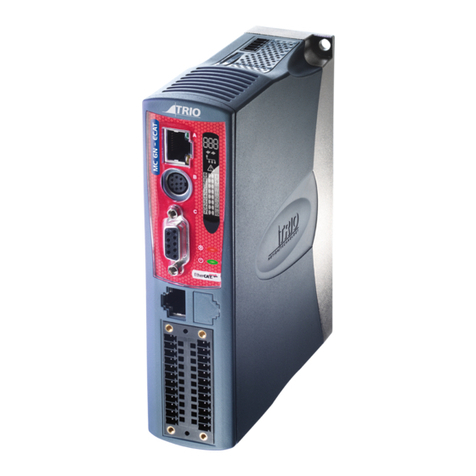
The low water level protection system (WMS) consists of a fail-safe, self-monitoring
signaling unit with periodic self-test and a sensor.
The signaling unit and sensor are connected by a two-wire signal cable of up to 10 m in
length.
The product combination detects and reports low water levels (lack of water).
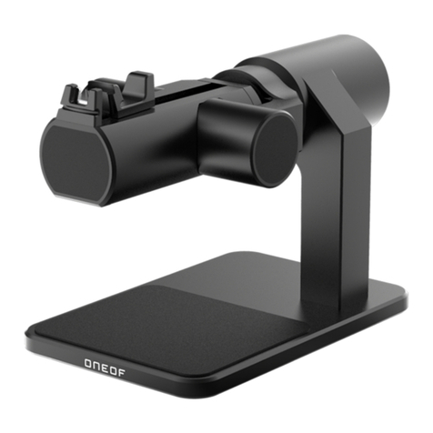
Sensor
Thesensorconsistsofametallicelectrodehousing,attedplasticcaseandanelectrode
rod that pulls out about 12 to 13 mm for functional testing.
The sensor is available in two versions:
fSensor DN 20:
Angledelectrodehousingwithtwo(DN20)weldedtting
(Øi=20mm,Øa=26.5mm)
1Electrode rod
2Plastic housing
3Electrode housing
4Union nuts G1", size 40
5Flange seal 30 x 21 x 2
6WeldedttingØ26.5
(DN20)
Fig. 1: Sensor DN 20

6
ENG:Installationandoperatinginstructions
Translationoftheoriginaloperatinginstructions
Signaling unit
The signaling unit contains indicators and controls in an impact-resistant plastic housing,
as well as all electronic components for evaluating and converting the sensor signal into a
digital output signal. The output is a zero potential relay contact.
The signaling unit is available in two versions:
fSignaling unit WMS 2-1:
With integrated power failure interlock; that is, after a power failure, the signaling unit
must be released.
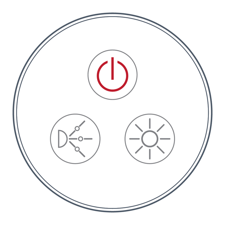
aGreen operation lamp
bTest button
cRed alarm lamp
d
Release button
eWithout function
Fig. 2: Signaling unit
Type Signaling unit Sensor Component marking
WMS 2-1 WMS 2-1 DN 20 TÜV.WBH.14-345
3.1 Function
The WMS monitors water levels in heating systems. If the water level drops below
minimum, the low water level protection system alerts.
The operating principle of the low water level protection system relies on the conductivity
oftheheatingwater.Ifthereisaowofwaterthroughthesensor,thelowwaterlevel
protectionsystemindicatessufcientsupplyofheatingwater.Ifthereisnoowofwater
through the sensor, the signaling unit immediately alerts.
Sensor
The sensor consists of an outer electrode and an inner movable electrode. The two
electrodes are connected via a two-core cable to the signaling unit. The signaling unit
constantly monitors the conductivity (electrical resistance) between the two electrodes.
The inner movable electrode can be moved about 12 to 13 mm upwards from the water

7
ENG
for testing. As a result, the contact with the water is interrupted simulating a lack of water.
The signaling unit immediately alerts. An integrated spring returns the inner electrode back
to the starting position.
Signaling unit
The signaling unit constantly monitors the conductance of the water or the electrical
resistance between the two electrodes of the sensor. If the measured conductance greater
than20µS,orthemeasuredresistanceislessthan50kΩthesignalingunitindicatesa
sufficient supply of heating water and an error-free sensor circuit. The red alarm lamp is
unlit.Iftheconductanceislessthan20µS,ortheresistanceisgreaterthan50kΩ,thisis
interpreted as a lack of water, wire break or defective sensor circuit. The red alarm lamp is
lit.
The WMS is designed to be fail-safe and self-monitoring. The electronics in the signaling
unit check the entire low water level protection system several times a second.
Errors in the sensor circuit and signaling unit are displayed as alarms. The low water level
protection system can only be released if the entire low water level protection system is
error-free, a sufficient power supply is available, and the water level is above the minimum;
i.e., the red alarm lamp is unlit and the built-in relay is energized.
The green power light is lit when the low water level protection system is supplied with
mains voltage. The test button allows a functional check which simulates an alarm
condition.
3.2 Operating modes
The WMS 2-1 has an internal power failure interlock; that is, after a power failure, the
signaling unit must be released via the “Release” button or via an external release contact

8
ENG:Installationandoperatinginstructions
Translationoftheoriginaloperatinginstructions
4. Technical data
Table 1: Technical data, sensors
Parameters DN 20
General data
Housing dimensions (W x H x D) 130 x 270 x 44 mm
Space requirement (W x H x D) 100 x 300 x 150 mm
Weight 0.8 kg
Electrode housing Brass
Electrode rod Steel type 316
Resistance Boiler water
Mechanical connection Weldedtting
Ø i = 20 mm, Ø a = 26.5 mm
Operating pressure Max. 10 bar
Connecting cable:
Standard length:
Max. length
H05RN-F, 2 x 1 mm²
1.5 m
10 m (shielded)
Sensor voltage Max. 12 V
Operating temperature range
Environment 0°Cto+55°C
Medium Max.120°C
Storage -10°Cto+60°C
Electrical safety
Degree of protection IP 54
Table2:Technicalspecications,signalingunit
Parameters Value
General data
Housing dimensions (W x H x D) 100 x 188 x 65 mm
Weight 0.7 kg
delay time Approximately 1 second by default
Connections 1 output relay (switch)
1 external releasing device
Operating temperature range
Environment 0°Cto+55°C

9
ENG
Parameters Value
Storage -10°Cto+60°C
Voltage supply
Rated voltage AC 230 V ± 10%, 50Hz
Rated power 5 VA
Power supply fuse T50mA
Switching capacity output relay (1
zero-potential double throw switch)
Max. 250 V, 2 A resistive load
Electrical safety
Electrical safety EN60730
Protection class II EN 60730
Degree of protection IP 40 EN 60529
Electromagnetic compatibility (EMC)
As per EN 61000-6-3 EN 61000-6-3
As per EN 61000-6-2 EN 61000-6-2
Cable glands on the signaling unit
The middle grommet can be replaced by an M20 cable
gland.
Threaded cable glands Cable diameter
M16 4,0-8,8mm
M20 8,0-12,5mm

10
ENG:Installationandoperatinginstructions
Translationoftheoriginaloperatinginstructions
Fig. 3: Signaling unit and installation frame for installation in control panels; on the right: panel cut-out
4.1 Permit, approval, registration
WMS corresponds to the VdTÜV Bulletin “Water Level 100" (Edition 02.2010), the EMC
Directive (2004/108/EC), the Low Voltage Directive (2006/95 / EC) and the Pressure
Equipment Directive (97/23/EC).
5. Transport and storage
CAUTION DAMAGE TO THE PRODUCT DURING TRANSPORT.
fDo not throw or drop the product.
fProtect against moisture, humidity, dirt and dust.
CAUTION DAMAGE TO THE PRODUCT DUE TO IMPROPER STORAGE.
fStore only in a clean and dry environment.
fStore products only within the acceptable temperature range.
6. Assembly and commissioning
RDo not install the signaling unit and sensor in areas with a risk of explosion.
6.1 Installing the sensor
fInstall the sensor in a connection line between the water and steam chambers on the
boiler or parallel to the supply line between the boiler and the circulation pump.
If the boiler already has threaded sockets for the sensor, install it there.
fThere must not be a circulation pump with check valve and/or a shut off valve
between the sensor and the boiler.
fIt must be impossible to shut off the pipe to the sensor; it must have an internal
diameter of 20 mm (¾").
fInstall the sensor in accordance with this operating manual and using the supplied
gaskets.

11
ENG
fEnsure that the sensor installation position is protected against foam and high surface
water load.
fNosupplywaterowmustbeconnectedtothewater-sideconnectingpipesonthe
sensor housing with the boiler.
fEnsure that the permissible ambient temperature is not exceeded on the sensor
housing outside the boiler; see Chapter 4, Page 9.
fIn order to avoid false alarms due to air bubbles (particularly for larger systems) the
inside diameter of the pipe to the sensor must not be substantially smaller than that of
the supply pipe. The distances from the sensor to the supply pipe must be kept short
and gradually reduced to ¾”.
fThe sensor must be installed vertically to the extent possible. Deviations of up to
45 ° from the vertical are permissible in exceptional cases; please make sure that no
air bubbles can accumulate in the sensor.
fInstall the sensor so that the lower edge of the sensor is at least 100 mm above the
highest point of the boiler..
CAUTION PERMANENT DAMAGE TO THE SENSOR DUE TO WELDING ON THE
SENSOR.
fDo not weld on the sensor.
aBoiler, rear side,
separate bushes for
sensor
bBoiler
Fig. 4: Installing the DN 20 sensor
6.2 Installing the signaling unit
R Installthesignalingunitonaat,rmanddrywallateyelevel.
RThe signaling unit must be accessible and visible at all times.
RThe signaling unit must be installed out of reach of water or splash water.
RDo not mount the signaling unit in a wet area.
RMake sure that the permissible ambient temperature at the signaling is not
exceeded; see Table 2 , Page 9.
RProtect the signaling unit against direct weather exposure in outdoor
installations.
RWhen installing the signaling unit take the necessary steps to ensure touch
protection.

12
ENG:Installationandoperatinginstructions
Translationoftheoriginaloperatinginstructions
REnsure a minimum degree of protection of IP 44 as per EN 60529 In the boiler
installation room.
R Theriskofexposureduringexternalreaswellastrafc,windandearthquake
exposure depends on the installation location and the site of the pressure
equipment and, may need to be assessed separately where appropriate.
1. Open signaling unit.
2. Fasten signaling unit on the wall (Aor B).
A 1 Fasten screw to wall. BDrill fastening holes in lower part with
5 mm Ø drill bit.
Fasten lower part to wall using enclosed
screws.
2Mount signaling unit.
3Mount signaling unit.

13
ENG
2. Wire the electrical connection as per Chapter 6.3, Page 15.
3. Close signaling unit.
6.3 Electrical connection
RMains voltage is interrupted and secured against switching back on.
fCallinaqualiedelectriciantoperformtheelectricalinstallationwork.
fObserve VDE requirements, accident prevention regulations and operating instructions
for the WMS, boilers and burner.
RThe power supply cable for the boiler room must be equipped with a main
switch outside the boiler room that simultaneously isolates all ungrounded
conductors with at least a 3 mm contact gap.
Power supply
DenNetzanschlussmiteinerfestverlegtenLeitungz.B.NYM-O2x1,5mm²herstellen.
1. Route the power supply cable through the right-hand compression coupling in
the signaling unit.
2. Route the phase conductor to terminal L1 and the neutral conductor to terminal
N.
3. The supply cable to the signaling unit must be separately fused (max. 10 A).

14
ENG:Installationandoperatinginstructions
Translationoftheoriginaloperatinginstructions
Sensor
1. Route the sensor cable through the left compression coupling in the signaling unit.
2. Connect the sensor cable to the two terminals on the signaling unit labeled “Sensor”.
Polarity does not need to be observed.
3. If the 1.5 m sensor cable is not long enough, the sensor cable can be extended using
2 x 1.5 mm² shielded cable. The length of the connecting cable between the sensor
and the signaling unit must not exceed 10 m.
4. The connecting cable must be routed so as to avoid external interference.
5. Ensure a minimum degree of protection of IP 65 as per EN 60529.
External release
6. A pushbutton (normally open contact) for externally releasing the WMS can be
connected to the two terminals on the signaling unit labeled “Rel.” at a distance of up to
10 m. The maximum voltage at these terminals is 12 V.
7. The button connections must be potential free.
8. If you use an external release, use the following electrical circuit as per EN 50156-1.
Output
The output signal from the WMS can be tapped using a zero-potential relay contact
(double throw switch). This relay contact is used for the safety shutdown of the furnace.
9. Route the electrical wiring (maximum 10 m) so that the power to the furnace is
interrupted in the event of an alarm.
During normal operation, the relay contact is energized; in the event of an alarm, the
relay contact is in idle position.
10.The output contact of the low water level protection system must be protected with an
external fuse of max. M 2 A.

15
ENG
Anschluss-Beispiele
1Mains fuse F1
2Sensor
3Boiler
4External release
(optional)
5External alarm
(optional)
6Release contactor
7Supply voltage
Fig. 5: Wiring example WMS 2-1
CAUTION FUNCTIONAL IMPAIRMENT OF ELECTRICAL EQUIPMENT DUE TO
VOLTAGE SPIKES WHEN SWITCHING OFF INDUCTIVE LOADS.
fWire inductive loads with commercially available standard RC combinations, e.g.,
0.1µF/100ohms.
6.4 Starting up the product
RCheck that the signaling unit and sensor are installed as per Chapter 6, Page 11.
RCheck that the sensor is leak tight.
RCheck that heating water has been topped up.
RCheck the electrical connection was implemented as per Chapter 6.3, Page 15.
RCheck that the sensor is connected to the signaling unit.
RCheck that the output relay is connected (if appropriate).
RCheck that the external power failure interlock has been implemented.
RCheck that the mains connection is in place.
RCheck that the ribbon cable is connected to the circuit board.
RCheck that the signaling unit is closed and fastened.

16
ENG:Installationandoperatinginstructions
Translationoftheoriginaloperatinginstructions
If all conditions are met, the product is ready for operation.
1. Power on using the site-side mains fuse.
Ä The green power indicator and red alarm light up.
2. WMS 2-1 manually release using the “Release” button or via the external
releasing device.
Ä During normal operation the red alarm lamp is unlit and the burner starts up.
4. Perform a functional check; see Chapter 6.5, Page 18.
6.5 Functional check
A functional check is performed manually by reducing the water level below the trigger
threshold, or by pulling the inner, movable electrode upwards.
This functional check must be carried out at regular intervals.
fPerform the functional check 1 x per year and after any maintenance or repairs.
At the sensor
1. For the functional check, pull up the electrode rod to its upper limit for at least 1
second.
ÄThe electrode rod is no longer in the boiler water, which simulates a lack of
water.
Ä The red alarm lamp on the control unit is lit, and the burner automatically shuts off.
2. Press the release button on the control unit to return to normal operating state.
Ä The red alarm lamp is unlit and the burner is operational.
At the signaling unit
1. Press the test button for at least 1 second.
ÄThe connection to the sensor is interrupted and the red alarm lamp is lit.
ÄThe burner shuts off automatically.
2. Press the release button on the control unit to return to normal operating state.
ÄThe red alarm lamp is unlit and the burner is operational.

17
ENG
7. Operation
The WMS monitors water levels in heating systems. If the water level drops below
minimum, the WMS alerts and the burner is shut off. Operation of the WMS only involves
regular monitoring to ensure that
fthe green lamp is lit.
fThe red alarm lamp is unlit.
fThe burner is operational.
8. Maintenance
8.1 Maintenance intervals
Table 3: Maintenance intervals
When Activity
1 x annually fPerform a functional check;
see Chapter 6.5, Page 18
Regularly fMake sure that the low water level protection system
and its surroundings are always clean, accessible and
visible
fKeep the sensor free from soiling and deposits; if
necessary, clean the sensor.
Donotaddanylm-forming,adhesiveorwater
polluting substances to the heating water
Defective mains fuse fReplace the mains fuse F1;
see Chapter 8.2, Page 20
8.2 Maintenance activities
Replacing the mains fuse F1
R Mains voltage is interrupted and secured against switching back on.
1. Open the signaling unit; see Chapter 6.2, Page 13.
2. Remove the transparent cover from the mains fuse F1.
3. Replace the mains fuse F1; see Table 2, Page 9.
4. Latch the transparent cover onto the mains fuse F1.
5. Connect the ribbon cable to the connection plug board.
6. Close the signaling unit; see Chapter 6.2, Page 13.
7. Switch on the mains voltage.
8. Release the signaling unit.

18
ENG:Installationandoperatinginstructions
Translationoftheoriginaloperatinginstructions
9. Malfunctions
Wassermangelsicherungen sind Sicherheitseinrichtungen und dürfen im Schadensfall nur
vom Hersteller repariert werden.
ReparaturendürfenausschließlichvonfachspezischqualiziertemPersonalausgeführt
werden.
Table 4: Malfunctions
Problem Possible cause Troubleshooting
Green operation
lamp is not lit
Mains voltage interrupted fRestore mains voltage
Defective mains fuse fReplace the mains fuse
Ribbon cable is not
connected to the printed
circuit board
fConnect the ribbon cable to
the PCB
Red alarm lamp Lack of water fTop up with boiler water
fPress the release button
Sensor not connected fConnect the sensor
Red alarm lamp
permanently lit;
WMS cannot be
released
Wire break in the sensor,
sensor cable or signaling
unit
fCheck the wiring
Pressing the test
button has no effect
Signaling unit is defective fReplace the signaling unit
Pulling the electrode
rod has no effect
Sensor/wiring defective fReplace sensor
fCheck wiring
Burner does not
start up
Lack of water fCheck whether the red
alarm lamp is lit
Wiring/burner defect fCheck wiring
fCheck burner
Miscellaneous
malfunctions
–fSend product to the
manufacturer

19
ENG
10. Decommissioning and disposal
1. Switch off the supply voltage.
2. Remove the low water level protection system (see Chapter 6, Page 11; steps in
reverse order).
3. To protect the environment, this product must not be disposed of with unsorted
domestic waste. Dispose of the product according to local regulations.
This product consists of materials which can be recycled by recycling specialists. We have
designed the electronics to use easily separable materials.
If you do not have the opportunity to dispose of the used equipment properly, please
contact us to agree disposal or return.
11. Warranty
The manufacturer’s warranty is 24 months from the date of purchase for this product.
Claims can be made in any country in which this product is sold by the manufacturer or an
authorized reseller.
12. Copyright
The copyright for this operating manual remains with the manufacturer. Reproduction,
translation and reproduction, in whole or in part, without written approval is not permitted.
The technical details of this operating manual are subject to change with respect to
descriptions, information and illustrations.
13. Customer satisfaction
Customer satisfaction is our top priority. If you have any questions, suggestions, or
problems with your product, please contact us.
14. Addresses
Youwillndtheaddressesofourworldwideofcesontheinterneton
www.amcogroup.com.

20
ENG:Installationandoperatinginstructions
Translationoftheoriginaloperatinginstructions
15. Notes
15.1 Registration documents
Table of contents
Languages:
Other flamco Control System manuals
