Electronikbox B-Box User manual
Installation manual Electronicbox Ver. B, 03.2020
No time for manuals? No problem, it will take only 2 minutes of your time to rea it an
you will have more fun while the installation of your new B - Box.
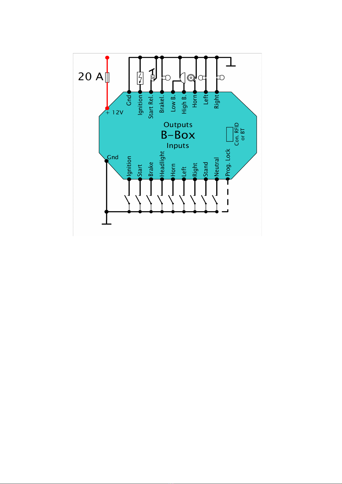
+12 Volt main (Re ): This is the 12 Volt main line. It is wired after the ignition key switch if you don´t use the
optional avaliable RFI antenna. It is wired irect to the battery if you use the RFI antenna as keyless go system.
Groun (Black): This cable is connected to battery minus / ground. By the way, it makes sense to connect the
handle bar ground with the frame ground with a wire. The bearrings to the fork have usually not a good
connection to the frame what might result in „funny“ unwanted effects.
Button input start: This input is wired to the start button.
Button - or killswitch input Ignition: This input is wired to the ignition switch or to the engine stop switch.
You switch on or off the ignition by a press on the button or by open the engine stop switch
Input brake switch: Just connect the brake switch(es) to this input. The brake light is activated by switching this input
to ground. By the way, the B - Box can let the brake light glow with 40 % if no brake switch is closed (...see option 1 in
the table). In this case you need only 1 cable to the rear light / brake light.
Button or switch input for the hea light: This is the connector for the head light switch. The head light changes
when this input is connected to ground. In the button mode you can switch off the head light by pressing and hold the
button for 2 seconds.
Button input horn: The horn output is activated when this input is switched to ground.
Button or switch input left in icators: The left flashers are activated when this input is switched to ground
Button or switch input right in icators: The right flashers are activated when this input is switched to ground.
By the way, you can activate an emergency flasher function by a press on both buttons at ths same time if the
„Button mode“ is be choosed.
Input si e stan switch: This input can be connected to the side stand. The ignition will switch off in the case if
the option 1 in the table is activated and the gear box of your bike is not in the neutral position.
Input neutral switch: If you have option 1 of the table activated you can only start your bike if the ignition
switch is closed to ground.
1 / 3

Input program lock: The adjusted settings in the B - Box can not be changed if this cable is connected to
ground. You should connect it to ground if all settings are ready made. However, you can change it at any time if
you open this connection.
Output ignition: This output is wired to the 12 Volt input of the ignition.
Output start relay: This output is wired to the starter relay and can supply max. 10 Ampere to the starter relay. on
´t wire the starter direct to this output!
Output brake light: This is the 12 Volt output to the brake light.
Output low beam: This output is wired to the low beam. The head light is switched off in the moment when you
start your bike
Output high beam: This output is wired to the high beam part of the head light.
Output horn: This is the switched output to the horn. Please note that the B-Box can supply maximum 3 Ampere for
this output. Some old horns have a higher current consumption what can destroy this output. A new horn usually
need about 2,5 Ampere and cost below 10,-.
Outputs for the flashers left an right: These switched outputs are connected to the direction indicators.
The flasher frequency is – of course constant, no matter if you use traditional bulbs or modern led lights.
Programming of the box:
You can change the functions of the box at any time if the „Program lock“ input is open. Press and hold the „Horn“
button and switch on the ignition. The box is in the „programming“ mode when you release the „Horn“ button. The
number of flashes of the direction indicators show you the row number in the table. The first row is the setting for the
side stand and neutral switch. You can activate the switches by pressing the „Left“ button or disable the switches by
pressing the „Right“ button. The box change to the next option after a press on a direction button. The box will store
the settings after 8 presses on the irection buttons.The following options are possible:
Number
Mo e
Left flasher button Right flasher button
Describtion
of
flashes
Neutral / sidestand
Safety control of ignition and start
1 x
switches enabled or
Active
isabled
function active or not.
disabled
The flasher switches off after 50
2 x
Flasher auto off
Off On
times.
Engine stop switch The ignition is on in switch mode if
3 x
or pushbutton for Engine stop switch
Push button
the contact is closed to ground or it
ignition on
switch on / off in button mode.
The ignition is controlled via
4 x
RFI antenna installed
not installed traditional switch or RFI chip.
Brake light and rear The brake light is complete off
5 x
Brake light mode Only brake light light combination when not in use or dim to 40 %
The starter and ignition is controlled
6 x
Start / Ignition One button
Two buttons
by 1 or 2 buttons
The head light is controlled by a
7 x
Head light control Switch
Push button
switch or a button
The direction indicators are
8 x
Indicator control
switch
button
controlled by a switch or 2 buttons.
The settings are stored in the B-Box after 8 presses on a direction button.
2 / 3

RFID Mo e: You can use the optional available antenna when you connect the antenna to the 4 pin connector and activate
the option 4 in the table. Then you just need to „teach“ the B -Box the unique code of the 2 electronic keys. The procedure is
almost similar to the procedure ofthe other options: Just press the „Left“ or „Right“ button and switch on the ignition. The box
„learn“ the code of the key when you hold it in front of the antenna. A flash of the direction indicators indicate that the box
have learned the code. Now just feel free to repeat the procedure with the other key and the other direction button. By the
way, don´t install the antenna behind any metal. This will reduce the maximum distance to the key or it will not work correct.
Bluetooth Mo ule: If you don´t use the RFI socket you can connect an optional available Bluetooth module on the port.
Just feel free to scan the QR code and download the Android app from our website:
Plug in the module to the 4 pin connector and switch on the ignition. Activate the Bluetooth option in your smart phone and
connect it to B-Box Remote. Open the app, scan for Buetooth devices and connect it with B-BoxRemote. That´s it. Now you
can control your bike via a touch on your smartphone. Please take care that the Bluetooth module is not covered with metal.
This will reduce the maximum distance to your smartphone. Also take care that the neutral switch is connected to your B-Box.
This will prevent you for unwanted funny effects when you try to start your bike and the gearbox is not in neutral position.
Installation:
Connect the red cable to plus 12 Volt and the black cable to the minus pole of the battery. You can connect the plus cable
irect to the battery if you use the RFID antenna.The re cable shoul be connecte after the ignition switch if you
on´t use the RFID antenna.The wires from the handle bar switches to the B-Box can be as thin as possible. There is no
significant current through these cables. The cables to the loads should have a minimum size of 0,75 qmm. Please take care
that the wires to the handlebar switches are as far as possible away wired from the ignition cables. It is always a good idea to
use a 6 wire shielded cable to the handlebar switches. These cables are available in every local computershop.
The B - Box should be installed by professional well trained engineers only. Please check your local regulations regarding the
traffic light rules in your country before of the use of the B - Box in your bike. Please be aware that we are not responsible for
any hazards, damages or disadvantages due to the use of the electronicbox. The electronicbox devices are registered under
the number E54933725 WEEE as B2C device. We also declare that the B - Box is conform to the CE and ROHS regulations
for the European market.
We tried to keep the functions of the B - Box and this manual as simple as possible. If you have any questions while the
installation please don’t hesitate to contact us at info@elektronikbox.de .
We wish you to have a lot of fun with your new B - Box in your bike
an of course always a safely trip!
3 / 3


