R&G LP0116 User manual

R&G Racing
Unit 1, Shelley’s Lane, East Worldham, Alton, Hampshire, GU34 3AQ
Tel: +44 (0)1420 89007 Fax: +44 (0)1420 87301 www.rg-racing.com Email: info@rg-racing.com
Page | 1
FITTING INSTRUCTIONS FOR LP0116 LICENCE PLATE BRACKET
DUCATI STREETFIGHTER 848 2012
THIS KIT CONTAINS THE ITEMS PICTURED AND LABELLED BELOW.
DO NOT PROCEED UNTIL YOU ARE SURE ALL PARTS ARE PRESENT.
Please note that the way the kit is packed does not necessarily represent the way of
mounting to the bike
THE PARTS SHOWN MAY BE REPRESENTATIVE ONLY (FOR CLARITY OF INSTRUCTIONS ONLY)
2
3
4
5
6
7
8
1
9
10
5
11

R&G Racing
Unit 1, Shelley’s Lane, East Worldham, Alton, Hampshire, GU34 3AQ
Tel: +44 (0)1420 89007 Fax: +44 (0)1420 87301 www.rg-racing.com Email: info@rg-racing.com
Page | 2
LEGEND
ITEM 1 = 150mm LENGTH OF HEAT SHRINK (x3).
ITEM 2 = M6x25mm LONG BUTTON HEADED BOLTS (x4).
ITEM 3 = LICENCE PLATE BRACKET COVER (TB0116 PART 2) (x1).
ITEM 4 = M6x6mm LONG BUTTON HEADED BOLTS (x4).
ITEM 5 = MINI INDICATOR ADAPTORS (I0033) (x4).
ITEM 6 = LICENCE PLATE ILLUMINATOR KIT (LA0002) (x1).
ITEM 7 = REFLECTOR (x1).
ITEM 8 = LICENCE PLATE BRACKET (TB0116) (x1).
ITEM 9 = SELF ADHESIVE CLIPS (CLIP 1) (x3).
ITEM 10 = SMALL CABLE TIES (x4).
ITEM 11 = M6 WASHERS (x8).
Please note that in cases where kits are packed with rubber washers holding the components onto
the bolt –the rubber washers should be thrown away!
TOOLS REQUIRED
Set of long series metric Allen keys to include 3 and 4mm A/F size.
Socket set to include 8mm A/F socket and wrench.
8mm spanner.
Electrical plier’s/crimps.
Small amount of superglue.
PICTURE 1PICTURE 2

R&G Racing
Unit 1, Shelley’s Lane, East Worldham, Alton, Hampshire, GU34 3AQ
Tel: +44 (0)1420 89007 Fax: +44 (0)1420 87301 www.rg-racing.com Email: info@rg-racing.com
Page | 5
FITTING INSTRUCTIONS
REMOVE THE PILLION SEAT OR SEAT COWL USING THE KEY.
REMOVE THE SEVEN BOLTS FROM UNDERNEATH THE ORIGINAL LICENCE
PLATE BRACKET AS ARROWED IN PICTURES 1 AND 2.
GENTLY LOWER THE ORIGINAL CABLE COVER/INDICATOR CLAMPING
BRACKET.
DISCONNECT THE ORIGINAL INDICATOR AND LICENCE PLATE ILLUMINATOR
WIRING SOCKETS AS SHOWN IN PICTURES 3 AND 4, THEN REMOVE THE
ASSEMBLY.
REMOVE THE ORIGINAL INDICATORS (NOTING THE CODE FOR WHICH SIDE
EACH FITS).
REMOVE THE TWO BOLTS ARROWED IN PICTURE 5 AND REMOVE THE
ORIGINAL TAIL UNIT.
REMOVE THE TWO BOLTS ARROWED IN PICTURE 6 AND REMOVE THE COVER.
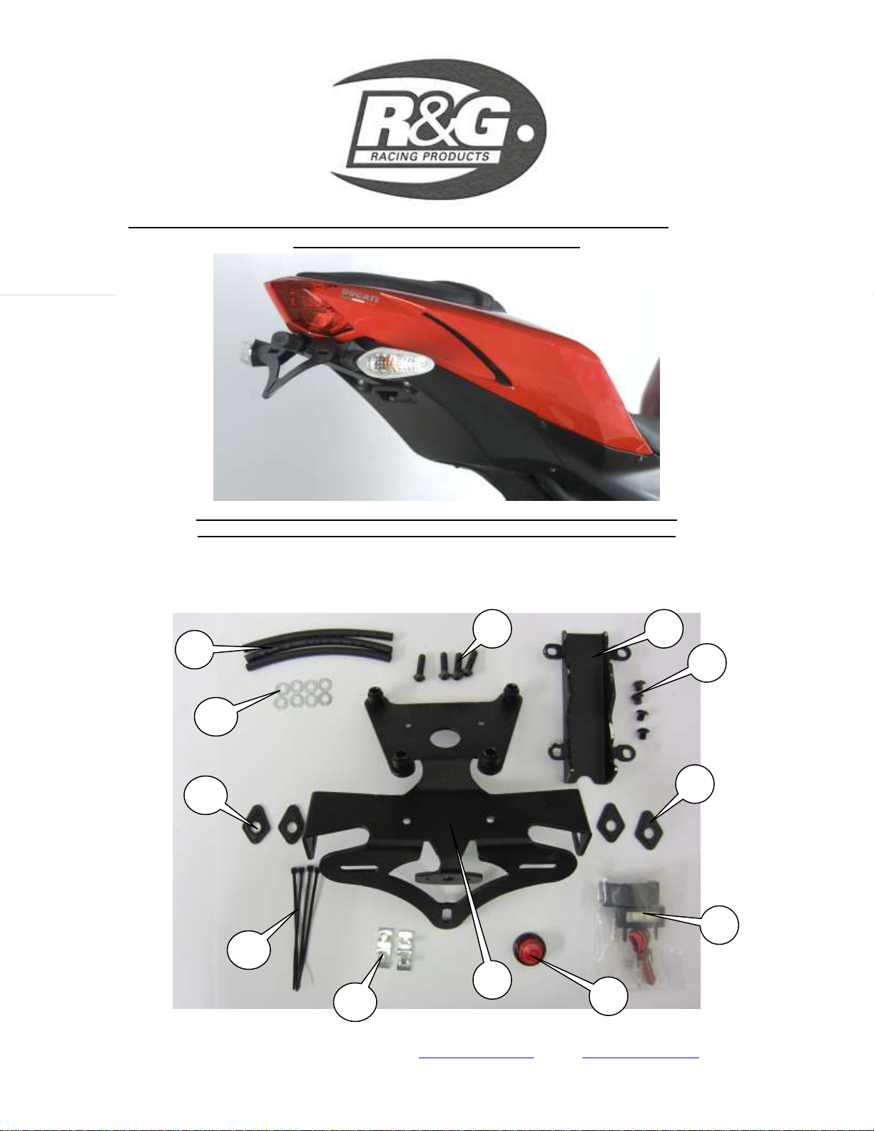
FIT THE NEW LICENCE PLATE ILLUMINATOR (ITEM 6) TO THE NEW LICENCE
PLATE BRACKET (ITEM 8) AS SHOWN IN PICTURE 10 (USE THE HEAT SHRINK TO
PROTECT THE WIRES) AND USING A SMALL AMOUNT OF SUPER-GLUE STICK
THE LIGHT SHROUD IN POSITION AS SHOWN IN THE TOP PICTURE (USE THE
SUPPLIED HEAT SHRINK (ITEM 1) TO PROTECT THE WIRES).
IF REUSING THE ORIGINAL INDICATORS FIT TO THE NEW LICENCE PLATE
BRACKET (ITEM 8) (THESE WILL BE A TIGHT FIT THROUGH THE SLOT SO IT
MAKES IT EASIER TO FIT IF YOU USE A SMALL AMOUNT OF WASHING-UP
LIQUID AND A FLAT BLADED SCREW-DRIVER) AS SHOWN IN PICTURE 8.
IF USING MINI INDICATORS USE THE FOUR DIAMOND SHAPED ADAPTORS
(ITEM 5) AND USE THE SUPPLIED HEAT SHRINK (ITEM 1) TO PROTECT THE
WIRES.
FEED ALL THE WIRES THROUGH THE LARGER HOLE IN THE NEW LICENCE
PLATE BRACKET AS SHOWN IN PICTURES 9 AND 11 (USE THE CABLE TIES (ITEM
10) SUPPLIED TO TIDY AND HOLD THE WIRES IN POSITION).
CONNECT THE INDICATOR AND LICENCE PLATE ILLUMINATOR PLUGS (PLEASE
NOTE YOU WILL HAVE TO REUSE THE ORIGINAL LICENCE PLATE
ILLUMINATOR PLUG SOCKET AND CUT AND SHUT THE WIRES USING THE
CONNECTORS SUPPLIED IN THE KIT).
OFFER THE NEW LICENCE PLATE BRACKET INTO POSITION AND USING THE
LONGER BUTTON HEADED BOLTS (ITEM 2) WITH WASHERS (ITEM 11) SECURE
INTO POSITION AS ARROWED IN PICTURE 12.
IT IS A GOOD IDEA TO CHECK OPERATION OF ALL LIGHTS AT THIS STAGE.
PLACE THE WIRING COVER (ITEM 3) INTO POSITION AND USE THE SHORTER
BUTTON HEADED BOLTS SECURE AS ARROWED IN PICTURE 13 (ROUTE THE
INDICATOR WIRES THROUGH THE LARGER CUT OUTS IN FRONT OF THE FRONT
TWO BOLTS AS SHOWN IN PICTURE 12.
REFIT THE UNDER SEAT COVER AS SHOWN IN PICTURE 14.
REFIT SEAT OR SEAT COWL AS ORIGINAL.
REFIT LICENCE PLATE (IT MAY REQUIRE DRILLING).
IMPORTANT: IF FITTING A FULL-SIZE LICENCE PLATE AND PLACING IT
FAR DOWN ON THE LICENCE PLATE HANGER, THERE IS A SMALL CHANCE

R&G Racing
Unit 1, Shelley’s Lane, East Worldham, Alton, Hampshire, GU34 3AQ
Tel: +44 (0)1420 89007 Fax: +44 (0)1420 87301 www.rg-racing.com Email: info@rg-racing.com
Page | 6
OF THE LICENCE PLATE HITTING THE BACK WHEEL UNDER HEAVY LOAD
AND OVER LARGE BUMPS IN THE ROAD. IT IS YOUR RESPONSIBILITY TO
CHECK FOR THIS POSSIBILITY AND TAKE AVOIDING ACTION. FAILURE TO
CHECK THIS COULD RESULT IN SERIOUS INJURY.
DEPENDING ON LOCAL LAWS, ATTACH ENCLOSED REFLECTOR IN AN
APPROPIATE LOCATION.
PLEASE TEST THE LICENCE PLATE ILLUMINATOR AND ALL LIGHTS BEFORE
RIDING.

R&G Racing
Unit 1, Shelley’s Lane, East Worldham, Alton, Hampshire, GU34 3AQ
Tel: +44 (0)1420 89007 Fax: +44 (0)1420 87301 www.rg-racing.com Email: info@rg-racing.com
Page | 7
Notice de montage
LP0116 Support de plaque
DUCATI STREETFIGHTER 848 2012
Ne pas procéder au montage s’en s’être assuré au préalable que les articles figurant sur la
photo du dessous soient bien présents.
La façon dont le kit est emballé ne représente pas nécessairement la façon de le monter
sur la moto.
Les parties représentées peuvent parfois être uniquement représentatives
(Pour la clarté des explications)
LEGENDE
Article 1 = 150mm Longueur de protection thermo rétractable (x3).
Article 2 = M6x25mm Longs boulons à tête ronde (x4).
Article 3 = Couvercle de support de plaque (TB0116 partie 2) (x1).
Article 4 = M6x6mm Longs boulons à tête ronde (x4).
Article 5 = Adaptateurs de mini clignotants (I0033) (x4).
Article 6 = Kit de feux de plaque (LA0002) (x1).
Article 7 = Réfléchissants (x1).
Article 8 = Support de plaque (TB0116) (x1).
Article 9 = Clips autocollants (Clip 1) (x3).
Article 10 = Petites attaches câble (x4).
Article 11 = M6 Rondelles (x8).
Notez que dans les cas où les kits sont emballés avec des rondelles en caoutchouc, composantes
du boulon - les rondelles en caoutchouc doivent être jetées !
Outils requis
Clés Allen de 3 et 4mm
Clé de 8mm
Clé à écrou de 8mm
Pince électrique
Petit pot de superglue
Instructions de montage
Enlever le siege passager.
Enlever les 7 boulons par le dessous du support de plaque d’origine (photo 1 et 2).
Baisser le support de fixation d’origine du couvercle des câbles.

R&G Racing
Unit 1, Shelley’s Lane, East Worldham, Alton, Hampshire, GU34 3AQ
Tel: +44 (0)1420 89007 Fax: +44 (0)1420 87301 www.rg-racing.com Email: info@rg-racing.com
Page | 8
Déconnecter les clignotants d’origine et les prises de feux de plaque (photo 3 et 4)
puis extraire l’ensemble.
Enlever les clignotants d’origine (En repérant bien quel code correspond à quel
coté).
Enlever les 2 boulons (photo 5) puis enlever l’empennage d’origine.
Enlever les 2 boulons (photo 6) puis retirer le couvercle.
Installer les feux de la nouvelle plaque (Article 6) sur le nouveau support de plaque
(Article 8) comme indiqué en photo 10 (Utiliser la protection thermo rétractable
pour protéger les câbles) et, en utilisant un peu de superglue, coller le linceul de
lumière en position (photo du haut) (Utiliser la protection thermo rétractable
fournie (Article 1) pour protéger les câbles.
Si vous décidez de réutiliser les clignotants d’origine, mettez les sur le nouveau
support de plaque (article 8) (Ce sera un ajustement limite à travers la fente et il
sera donc plus facile d’installer si vous utilisez du liquide vaisselle à l’aide d’un
tournevis plat par exemple) (photo 8).
Si vous utilisez des mini clignotants, utilisez les 4 adaptateurs en forme de diamante
(Article 5) et utiliser la protection thermo rétractable pour protéger les câbles
(article 1).
Passez tous les câbles à travers le trou le plus gros dans le nouveau support de
plaque (photo 9 et 11) (Utiliser les attaches câbles (Article 10) fournis pour
maintenir correctement les câbles en position).
Connecter les clignotants et les prises de feux de plaque (Vous devrez réutilisez la
prise d’origine des feux de plaque et couper puis fermer les fils en utilisant les
connecteurs fournis dans le kit).
Mettre le nouveau support de plaque en position puis utiliser les longs boulons à
tête ronde (Article 2) avec les rondelles (Article 11) pour fixer en position (photo
12).
Tester tous les feux à ce stade du montage.
Placer le couvercle des câblages (Article 3) en position puis utiliser les boulons à tête
ronde les plus courts pour fixer (photo 13). Passer les câbles de clignotants à travers
la plus grosse fente devant les 2 boulons de devant (photo 12).
Remettre le couvercle sous le siège (photo 14).
Remettre l’ensemble du carénage comme à l’origine.
Remettre la plaque (peut nécessiter un forage).
IMPORTANT: SI LE MONTAGE S’OPERE AVEC UN PLAQUE D’IMMATRICULATION DE
GRANDE TAILLE, IL EST DE VOTRE RESPONSABILITE DE CONTROLER QU’AUCUN
RISQUE DE COLISION ENTRE LA PLAQUE ET LA ROUE ARRIERE NE PUISSE
S’EFFECTUER. CELA POURRAIT SE PRODUIRE NOTAMMENT EN CAS DE TROUS OU DE
BOSSES PRESENTS SUR LA ROUTE.
NE PAS EFFECTUER DE VERIFICATION POURRAIT ENTRAINER DES BLESSURES
GRAVES POUR LE MOTARD.

R&G Racing
Unit 1, Shelley’s Lane, East Worldham, Alton, Hampshire, GU34 3AQ
Tel: +44 (0)1420 89007 Fax: +44 (0)1420 87301 www.rg-racing.com Email: info@rg-racing.com
Page | 9
Selon la loi locale, positionner les réflecteurs à leur emplacement adéquat.
Tester l’ensemble des feux avant de prendre la route.
ISSUE 1 13/04/2012 (NSY)
CONSUMER NOTICE
The catalogue description and any exhibition of samples are only broad indications of the Products and R&G may make design
changes which do not diminish their performance or visual appeal and supplying them in such state shall conform to the order. The
Buyer acknowledges no representation or warranty (other than as to title) has been given or will apply to the Products other than those
in R&G’s order or confirmation and the Buyer confirms it has chosen the Products as being of merchantable quality and suitable for
its particular purposes. Where R&G fits the Products or undertakes other services it shall exercise reasonable skill and care and rectify
any fault free of charge unless the workmanship has been disturbed. The Buyer is responsible for ensuring that the warranty on the
motorcycle is not affected by the fitting of the Products. On return of any defective Products R&G shall at its option either supply a
replacement or refund the purchase money but shall not be liable if the Products have been modified or used or maintained otherwise
than in accordance with R&G’s or manufacturer’s instructions and good engineering practice or if the defect arises from accident or
neglect. Other than identified above and subject to R&G not limiting its liability for causing death and personal injury, it shall not be
liable for indirect or consequential loss and otherwise its liability shall be limited to the amounts paid by the Buyer for the Products or
the fitting or service concerned. These terms do not affect the Buyer’s statutory rights.
R&G RACING RETURNS POLICY (NON-FAULTY GOODS)
Returns must be pre-authorised (if not pre-authorised the return will be rejected). Goods may only be returned direct to us if they were
purchased direct from us (customer must prove if necessary). Otherwise to be returned to original vendor. Goods must be in re-
sellable condition, in the opinion of R&G Racing. All returns are subject to a 25% restocking and handling fee (25% of the gross value
exc. P&P –at the prevailing price at time of purchase). The customer must pay any and all carriage charges. No returns of
discontinued products, unless within 14 days of purchase. This policy does not affect your statutory rights and does not refer to faulty
goods.

R&G Racing
Unit 1, Shelley’s Lane, East Worldham, Alton, Hampshire, GU34 3AQ
Tel: +44 (0)1420 89007 Fax: +44 (0)1420 87301 www.rg-racing.com Email: info@rg-racing.com
Page | 10
MONTAGEANLEITUNG FÜR LP0116 KENNZEICHENHALTER
DUCATI STREETFIGHTER 848 2012
ALLE GELIEFERTEN TEILE SIND UNTEN ABGEBILDET UND GEKENNZEICHNET. BEVOR
SIE MIT DER MONTAGE BEGINNEN, ÜBERPRÜFEN SIE SORGFÄLTIG, DASS ALLE TEILE
VORHANDEN SIND.
Hinweis: Die Verpackung der Teile stellt nicht die Reihenfolge der Montage dar.
DIE UNTEN ABGEBILDETEN TEILE DIENEN LEDIGLICH ZUR ERKLÄRUNG
2
3
4
5
6
7
8
1
9
10
5
11

R&G Racing
Unit 1, Shelley’s Lane, East Worldham, Alton, Hampshire, GU34 3AQ
Tel: +44 (0)1420 89007 Fax: +44 (0)1420 87301 www.rg-racing.com Email: info@rg-racing.com
Page | 11
LIEFERUMFANG
ARTIKEL 1 = 150mm SCHRUMPFSCHLAUCH (x3).
ARTIKEL 2 = M6x25mm INBUSSCHRAUBEN (x4).
ARTIKEL 3 = KENNZEICHENHALTERABDECKUNG (TB0116 PART 2) (x1).
ARTIKEL 4 = M6x6mm INBUSSCHRAUBEN (x4).
ARTIKEL 5 = MINIBLINKER-ADAPTER (I0033) (x4).
ARTIKEL 6 = KENNZEICHENBELEUCHTUNG (LA0002) (x1).
ARTIKEL 7 = RÜCKSTRAHLER (x1).
ARTIKEL 8 = KENNZEICHENHALTER (TB0116) (x1).
ARTIKEL 9 = SELSTKLEBENDE KABELBINDERHALTER (CLIP 1) (x3).
ARTIKEL 10 = KLEINE KABELBINDER (x4).
ARTIKEL 11 = M6 UNTERLEGSCHEIBEN (x8).
Hinweis für Kits mit Plastikunterlegscheiben an den Schrauben –Diese Plastikunterlegscheiben
werden nicht für den Einbau benötigt!
SIE BENÖTIGEN FOLGENDES WERKZEUG:
Satz Inbusschlüssel inkl. Größe 3 & 4 A/F
8 mm Steckschlüssel
8mm spanner Gabelschlüssel.
Elektroniker Zange
Kleine Menge Sekundenkleber
ABBILDUNG 1ABBILDUNG 2

R&G Racing
Unit 1, Shelley’s Lane, East Worldham, Alton, Hampshire, GU34 3AQ
Tel: +44 (0)1420 89007 Fax: +44 (0)1420 87301 www.rg-racing.com Email: info@rg-racing.com
Page | 14
MONTAGEANLEITUNG
ENTFERNEN SIE DEN FAHRERSITZ ODER SITZVERKLEIDUNG MITTELS
SCHLÜSSEL.
ENTFERNEN SIE DIE SIEBEN SCHRAUBEN UNTER DEM
ORIGINALKENNZEICHENHALTER (SIEHE ABBILDUNGEN 1 UND 2).
LANGSAM DIE ORIGINAL KABELABDECKUNG/BLINKER-KLEMMHALTERUNG
HERABSETZEN.
TRENNEN SIE DIE KABELVERBINDER FÜR DIE ORIGINALBLINKER- UND DIE
KENNZEICHENBELEUCHTUNG (SIEHE ABBILDUNGEN 3 UND 4), DANN
ENTFERENEN SIE DIESE.
ENTFERNEN SIE DIE ORIGINALBLINKER (NOTIEREN SIE DIE KENNZEICHNUNG
FÜR DIE PASSENDEN VERBINDUNGEN AUF JEDER SEITE).
ENTFERNEN SIE DIE ZWEI SCHRAUBEN (ABBILDUNG 5) UND ENTFERNEN SIE
DEN ORIGINALKENNZEICHENHALTER.
ENTFERNEN SIE DIE ZWEI SCHRAUBEN IN ABBILDUNG 6 UND ENTFERNEN SIE
DIE ABDECKUNG.
MONTIEREN SIE DIE NEUE KENNZEICHENBELEUCHTUNG (ARTIKEL 6) AM
NEUEN KENNZEICHENHALTER (ARTIKEL 8) WIE IN ABBILDUNG 10
ABGEBILDET (VERWENDEN SIE DEN SCHRUMPFSCHLAUCH, UM DIE KABEL ZU
SCHÜTZEN). KLEBEN SIE DIE LICHTABDECKUNG, WIE IN DER OBEREN
ABBILDUNG GEZEIGT, MIT SEKUNDENKLEBER FEST (VERWENDEN SIE DEN
MITGELIEFERTEN SCHRUMPFSCHLAUCH (ARTIKEL 1), UM DIE KABEL ZU
SCHÜTZEN).
WENN SIE DIE ORIGINALBLINKER VERWENDEN, MONTIEREN SIE DIE AUF DEM
NEUEN KENNZEICHENHALTER (ARTIKEL 8) (DIE SPALTE IST SEHR ENG –
DAHER IST ES ETWAS EINFACHER, WENN SIE ETWAS SPÜLMITTEL UND EINEN
FLACHSCHRAUBENDREHER VERWENDEN) WIE IN ABBILDUNG 8.
WENN SIE DIE MINI-BLINKER MONTIEREN, VERWENDEN SIE DIE VIER
MINIBLINKER ADAPTER (ARTIKEL 5) UND VERWENDEN SIE DEN
MITGELIEFERTEN SCHRUMPFSCHLAUCH (ARTIKEL 1), UM DIE KABEL ZU
SCHÜTZEN.
FÜHREN SIE ALLE KABEL DURCH DAS GRÖSSERE LOCH IM NEUEN
KENNZEICHENHALTER WIE ABGEBILDET (ABBILDUNGEN 9 UND 11).
VERWENDEN SIE DIE KABELBINDER (ARTIKEL 10) UM DIE KABEL ORDENTLICH
FESTZUBINDEN.
VERBINDEN SIE DIE BLINKER- UND KENNZEICHNBELEUCHTUNGS-
STECKVERBINDER (HINWEIS: SIE MÜSSEN DEN
ORIGINALKENNZEICHENBELEUCHTUNGSSTECKER WIEDER VERWENDEN UND
DIE KABEL ABTRENNEN, ABISOLIEREN UND MIT DEN KABELVERBINDER VOM
KIT VERSEHEN).
DEN NEUEN KENNZEICHENHALTER IN POSITION HALTEN UND MIT DEN
LÄNGEREN INBUSSCHRAUBEN (ARTIKEL 2) UND UNTERLEGSCHEIBEN
(ARTIKEL 11) BEFESTIGEN (SIEHE ABBILDUNG 12).
ÜBERPRÜFEN SIE DIE FUNKTION DER BELEUCHTUNG.
BEFESTIGEN SIE KENNZEICHENHALTERABDECKUNG(ARTIKEL 3) MIT DEN
KÜRZEREN INBUSSCHRAUBEN (ABBILDUNG 13). DIE BLINKERKABEL DURCH

R&G Racing
Unit 1, Shelley’s Lane, East Worldham, Alton, Hampshire, GU34 3AQ
Tel: +44 (0)1420 89007 Fax: +44 (0)1420 87301 www.rg-racing.com Email: info@rg-racing.com
Page | 15
DIE GRÖSSEREN AUSSCHNITTE (VOR DEN ZWEI SCHRAUBEN) VERLEGEN
(SIEHE ABBILDUNG 12).
MONTIEREN SIE DEN UNTERE SITZABDECKUNG (ABBILDUNG 14).
MONTIEREN SIE DEN SITZ ODER SITZABDECKUNG
MONTIEREN SIE DAS AMTLICHE KENNZEICHEN (BOHRUNGEN IM
KENNZEICHEN EVTL. NOTWENDIG).
WICHTIG: WENN EIN GROSSES KENNZEICHEN ZU WEIT NACH UNTEN
MONTIERT WIRD, BESTEHT BEI SCHWEREM LAST ODER DURCH GROSSE
BODENWELLEN EIN GERINGES RISIKO, DASS DAS KENNZEICHEN AN DAS
HINTERRAD STOSSEN KANN. ES LIEGT IN IHRER VERANTWORTUNG DIES
ZU ÜBERPRÜFEN UND, WENN NOTWENDIG, VORZUBEUGENDE
MASSNAHMEN ZU ERGREIFEN. DIE NICHTBEACHTUNG DIESES
SICHERHEITSHINWEIS KANN ZU SCHWEREN VERLETZUNGEN FÜHREN.
ENTSPRECHEND DER GESETZLICHEN VORSCHRIFTEN, DEN MITGELIEFERTEN
RÜCKSTRAHLER AN DIE DAFÜR VORGESEHENE STELLE ANBRINGEN.
ÜBERPRÜFEN SIE DIE FUNKTION DER BELEUCHTUNG (BLINKER UND
KENNZEICHENHALTERBELEUCHTUNG) VOR GEBRAUCH DES FAHRZEUGES.
AUSGABE 1 13/04/2012 (NSY)
Table of contents
Languages:
Other R&G Bicycle Accessories manuals
Popular Bicycle Accessories manuals by other brands

Shimano
Shimano TIAGRA ST-4500 - TECHNICAL Service instructions

Electric Bike Technologies
Electric Bike Technologies E-BikeKit owner's manual

ROSE Bikes
ROSE Bikes PRO BODY-PROTECTOR SPS-1 owner's manual

Burley
Burley d'lite Owner's instruction and safety manual

EVBIKE
EVBIKE EVBIKE-SET-36V-26F user manual

Bosch
Bosch Kiox 300 quick start guide