ELEKTRA VCD10 User manual

www.elektra.eu
Instrukcja montażu
ELEKTRA
PL
• VCD10
• VCD17
Heating
Cables
Installation manual UK
Инструкция по монтажу RU


Application
ELEKTRA VCD10 and VCD17 heating cables
are primarily intended for use in the rooms with atile
or natural stone oor covering. Additionally they
can be used with such oor covering materials as:
• Fitted carpet,
• Vinyl ooring,
• Parquet or other wooden covering,
• Laminate.
Fitted carpets and vinyl ooring, however, should
be suitable for use with electric underoor heat-
ing and bear the following markings:
ELEKTRA VCD heating cables are laid (at construc-
tion stage) on the slab oor or concrete suboor
with a layer of thermal insulation in order to re-
duce heat loss. Then the cables are covered with
an anhydrite or cement screed.
tted
carpet
PVC
ooring
The applications of the ELEKTRA VCD heat-
ing cables also include protection of pipes
against freezing. The installation instructions
for this particular application is available at:
www.documentation.elektra.eu.
!
3

ELEKTRA
Heating Cables
Characteristics
of the heating cables
• The heating cables are produced in ready-
made units of the following lengths:
ELEKTRA VCD10 from 7,5 up to 225m,
ELEKTRA VCD17 from 5,5 up to 172 m.
• The cables are terminated at one end with
a2.5 m-long power supply conductor,
andajoint at the other.
• Heat output
ELEKTRA VCD10: 10 W/m,
ELEKTRA VCD17: 17 W/m.
• Power supply voltage: 230 VAC, 50/60 Hz.
• External dimensions: ≈ 5 x 7 mm.
• Min. installation temperature: -5°C.
• Min. cable bending radius: 3.5 D.
• Heating cables are screened, and their mains
connection via a residual current device con-
stitutes effective anti-shock protection.
Multi-wire
heating core
XLPE insulation
PET covered
aluminium foil shield
Tinned
copper braiding
Heat resistant PVC
external sheath
ELEKTRA VCD heating cables can be used as:
• primary room heating systems, constituting
exclusive heat source in rooms,
• secondary room heating systems, to achieve
the “warm oor effect”.
4

The label features the following pictograph:
Single-side powered
heating cables
Self-adhesive label
• “cold” power supply conductor
• double-core ELEKTRA VCD heating cable
• connecting joint between the power supply
conductor and the heating cable
1
2
3
Note:
Heating cables’ heating output may vary with
+5% and -10% from the label values.
Heating cables are designed for the rated voltage
230 VAC, 50 Hz.
!
1
2 3
5

ELEKTRA
Heating Cables
Materials and tools
required for the installation of heating cables
• ELEKTRA VCD heating cable,
• thermal insulation (XPS, hard styrofoam –
min. density 20 kg/m2or hard mineral wool),
• PE foil,
• ELEKTRA TME installation tape,
• temperature controller,
• 1.5 m-long protective conduit,
• 2.5 m-long protective conduit,
• deep installation box,
• ohmmeter,
• megaohmmeter,
• tools for wall chasing.
Note:
Never cut the heating cable.
Never shorten the heating cable, only the power
supply conductor may be shortened if required.
Never squash the “cold tail”.
Do not ever undertake on your own any at-
tempts to repair the heating cables, and in case
any damage is detected, report the damage to
an ELEKTRA authorized installer.
Never stretch or strain the cable excessively,
norhit it with sharp tools.
Do not install the ELEKTRA VCD heating cable
when ambient temperature drops below -5°C.
Do not lay the heating cable in places where xed
oor level furnishing has been planned (e.g. oor
level wardrobes).
Never lead the end joint and the connecting
joint between the heating cable and the power
supply conductor out of the surface. Both joints
must be placed within the layer of the concrete
or self-levelling slab.
Do not use any nails or screws for the installa-
tion purposes.
!
6

Note:
Heating cables must be installed according with
the Instructions.
Mains connection of the heating cables should
be performed by an authorized electrician.
Heating cables should be always positioned
in the safe distance from other heat sources
(e.g. hot water pipes), the min. distance is 25 mm.
!
Type of the
heating
system
Floor type Recommended
heating cables Output per m2 of the oor
“Warm oor
effect”
Ceramic, stone and
PVC oorings
VCD10
VCD17 85 W/m²
Other oorings VCD10 65 W/m²
Primary
heating
systems
Ceramic, stone and
PVC oorings
VCD10
VCD17 Requires designing the
heating system and its
controls by a designer,
dealer or authorized
installer.
Other oorings VCD10
General information
7

ELEKTRA
Heating Cables
Installation of the higher output (per1 m2) is nec-
essary if the oor warm-up time is to be reduced,
also if the heating system is not designed to oper-
ate continuously e.g. in hotel rooms, ofces etc.,
as well as when temperature controllers with
temperature setback are applied.
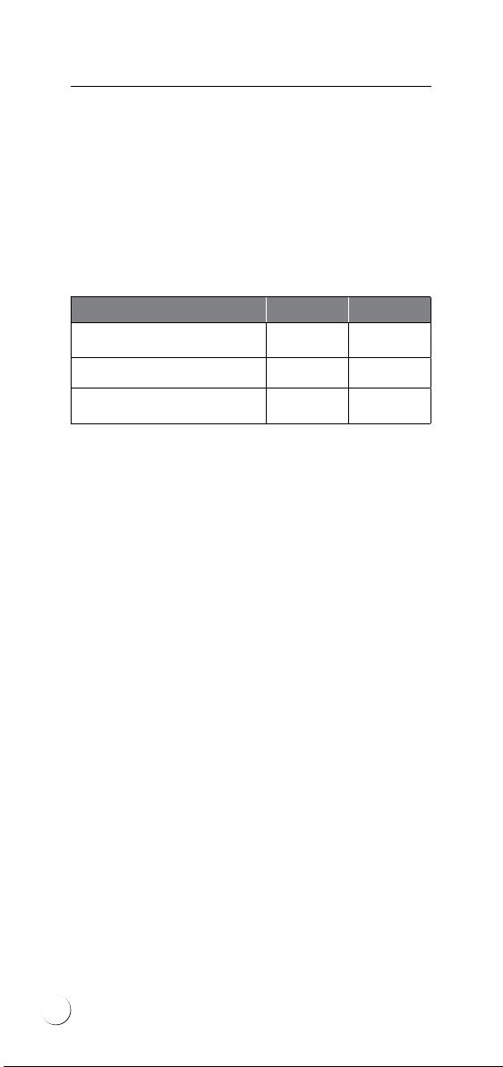
Min. permissible spacing between cables is as
follows:
Floor type VCD10 VCD17
Stone or ceramic oorings 7cm 10 cm
PVC 8 cm 12 cm
Wood, tted carpet 10 cm —
Max. spacing between cables should not exceed
20 cm in order to prevent cold spots.
Types of screed
The two following screeds can be utilised with
oor heating:
• anhydrite screed – with the advantages of
short curing time (approx. 7 days), as well as
insignicant linear shrink and low porosity.
Large areas can be covered with this type
of screed (up to 300 m2), with no need for
expansion joints. Owing to low porosity, the
screed will efciently transfer heat and the
oor will warm up faster than in case of ce-
ment slabs. This type of screed is, however,
sensitive to moisture and cannot be used in
rooms with continuous elevated moisture
levels;
• cement screed – with the advantage of mois-
ture and high temperature resistance. Due to
large linear shrink, with the oors larger than
3 0 m 2, when the side length exceeds 6 m,
expansion joints must be provided.
8

The screed should be separated from the side
walls with expansion tape. Screeds for oor heat-
ing must not be rigidly tied to the suboor or
walls (so called oating oor), to prevent down-
ward and sideward heat loss to the suboor and
external walls.
*Please ensure that the screed thickness complies with local
building regulations.
Temperature control
A temperature controller is a core component
ofany oor heating system.
Controllers are used as the connecting element
between heating cables and domestic electric
circuit. Controllers will ensure the desired level
ofoor or air temperature.
• If heating cables act only as the supplement
of existing (primary) heating system, users
will be mostly interested in achieving the so
called “warm oor effect” – then tempera-
ture controllers are recommended equipped
with only oor sensors maintaining desired
levels of oor temperature.
Technical
parameters of oor
slabs
Anhydrite
screed
Cement
screed
Screed thickness*35 – 60 mm 50 – 80mm
Heat transfer 2 . 0 W / m ² K 1.0 – 1.1
W/m²K
Curing time 7 days 28 days
Max. area with no
expansion joints 3 0 0 m ² 3 0 m ²
Porosity 8% 15 – 20%
9

ELEKTRA
Heating Cables
• If heating cables are meant as the primary
heating system, users will aim at achieving an
optimal level of room air temperature – then
temperature controllers are required with
air temperature measurement functional-
ity, i.e.acontroller with an air sensor and
limiting oor sensor (this controller type will
measure air temperature, and simultaneously
its oor sensor will protect oor and cable
from overheating).
For temperature control, manual controllers
maintaining steady temperature levels can be
applied, as well as programmable controllers
with daily or weekly temperature programming
options.
Heating system
Temperature controller type
Manual
Programmable
Primary ELEKTRA
OTD2 1999
ELEKTRA
OCD4 1999
Secondary (“warm
oor effect”)
ELEKTRA
OTN 1991
OTD2 1999
ELEKTRA
OCC2 1991
OCD4 1999
DIGI2p
Temperature controllers can be
placed in a common frame with
a light switch (not UK)
Temperature
sensor
10

Installation
Stage 1: Electric works
At this stage, it is required to:
1. Select the proper place for the temperature
controller – due to aesthetic and practical rea-
sons, the optimal location seems to be light
switch area (the temperature controller can
be placed in the common frame with the light
switch). (not UK)
2. Install the deep installation box, where the
temperature controller will be positioned.
3. Feed the power supply into the installa-
tionbox.
4. Lead two protective conduits (of the diameter
15 mm) out of the installation box towards the
oor. Position them in the previously carved
chase. One conduit (2.5 m-long) will host the
temperature sensor’s cable (at the stage of the
heating cable installation), the second conduit
(1.5 m-long) will host the heating cable’s power
supply conductor.
If the heated zone is not directly adjacent to the
wall with the temperature controller (when the
protective conduit will extend into oor with
over1.0 m), a pull box should be installed by the
oor. This solution will facilitate the possible fu-
ture replacement of the oor sensor, if it proves
necessary to do so.
The so called “draw wire” – exible cable placed
inside the conduit, will enable to easily insert the
oor sensor’s cable, as well as the heating cable’s
power supply conductors, into the deep instal-
lation box – only when plastering works or oor
nishing works are complete.
11

ELEKTRA
Heating Cables
Note:
Protective conduits must not be bent at 90° at the
wall-oor edge (arched shape must be retained).
The arched shape of the protective conduits will
facilitate the possible future replacement of the
oor sensor, if it proves necessary to do so.
!
• Power supply conductor
• Deep installation box for the temperature
controller’s installation
• Protective conduit for the oor sensor
• Protective conduit for the heating cable’s
power supply conductors
• So called ”Draw Wire”
• Pull box
1
2
3
4
5
6
12

Stage 2: Heating cable’s
installation
Place in turn the following on the levelled sub-
oor or concrete underlay:
• thermal insulation layer,
• PE foil.
Before commencing the layout of the selected
heating cable:
• calculate the required distancing of the heat-
ing cable,
• mark on the oor places dedicated for xed
furnishings (wardrobes, kitchen cupboards,
bath tub, shower, toilet).
In order to calculate the required heating ca-
ble’s spacing, prepare the drawn schematics of
the heating cable’s arrangement, or alternative-
ly apply the following formula:
a-a =
where:
a-a – spacing between cables
S – floor surface area, for the floor heated
with the heating cable
L – heating cable’s length
P – floor surface perimeter, for the floor
heated with the heating cable
S
L+0.5P
• Place the ELEKTRA TME installation tape (to
secure the heating cable) with the distancing
of 40 cm.
• Position the heating cable, starting from the
power supply conductor’s end, ensuring that
the power supply conductor will freely reach
the installation box.
The heating cable should be separated from the
walls and xed furnishings with the distance
equal to planned cable spacing.
13

ELEKTRA
Heating Cables
Stage 3: After the heating
cable has been laid
At this stage, it is necessary to undertake the fol-
lowing steps:
• stick into the Warranty Card the self-adhesive
label, positioned on the power supply con-
ductor of the heating cable,
• feed the power supply conductor of the heat-
ing cable into the installation box through
the protective conduit mounted at the stage
of electric works,
• install the oor sensor centred between the
heating cables and secure it with the installa-
tion tape,
• feed the temperature sensor’s cable into the
installation box through the protective con-
duit mounted at the stage of electric works,
14

• seal the end of the protective conduit with
the temperature sensor, thus protecting the
sensor against moisture,
• in the Warranty Card, prepare a sketch of the
heating cable’s layout and temperature sen-
sor’s positioning.
Stage 4: Measurements
Perform the measurements of:
• heating core’s resistance,
• insulation’s resistance.
The measurement results of the heating core’s re-
sistance should not vary from the label value with
more than -5%, +10%.
The heating cable insulation’s resistance, as
measured with an appliance of the rated voltage
1000V (megaohmmeter), should not drop below
10mΩ. Enter the results into the Warranty Card.
After the oor has been completed, repeat the
measurements to check whether the heating ca-
ble has not been damaged during oor installa-
tion works.
Note:
The oor sensor should be positioned centrally
between the heating cables.
!
Heating core’s resistance
measurement
(brown
or black)
(blue)
15

ELEKTRA
Heating Cables
Stage 5: Floor works
Cover the entire oor surface with the
min. 35mm-thick anhydrite screed,
orthemin.50mm-thick cement screed.
Never lead the end joint and the connecting joint
between the heating cable and the power supply
conductor out of the surface. Both joints must
be placed within the layer of the concrete or self-
levelling slab.
Note:
The danger of damage to the heating cable exists
while laying the screed, through the wheelbarrow
used to transport the screed, shovels and other
sharp-edged tools. That is why it is recommended
to lay platforms enabling safe movement and
transfer of wheelbarrows.
!
Note:
After the slab has been laid, it is necessary to
repeat the measurements of:
• heating core’s resistance,
• insulation’s resistance.
Compare the results and enter them into the
Warranty Card.
!
(brown or
black)
(yellow-green)
Insulation’s resistance
measurement
Power supply conductors
Ohmmeter
Megaohmmeter
16

Stage 6: Temperature
controller’s installation
The heating cable connection to the domestic
electric circuit should be performed by an author-
ised electrician.
The connection of the:
1. mains,
2. power supply conductors (“cold” cables) of
the heating cable,
3. temperature sensor.
in the installation box with the temperature
controller should be executed according to the
schematics included in the temperature control-
ler’s Instructions.
Note:
PE wires of the heating cable should be connected
to the protective (green-yellow) wire of the do-
mestic electric circuit via the dedicated terminal
“
╩
” in the temperature controller. If no such ter-
minal is present, the connection should be made
separately with a branch connector (connection
block) placed in the installation box.
If more than one cable has been installed in one
room, the cables must be connected in parallel,
i.e. the same type of cables (cables of the same
colour) should be connected to the same con-
troller’s terminal.
!
17

ELEKTRA
Heating Cables
Operation
The operation of the heating system is limited to
setting required temperature with the tempera-
ture controller.
Please bear in mind that the entire (or part of the)
oor surface constitutes the heating element in
this kind of system, therefore no modications
of the either furniture arrangements or type,
or room destination may be introduced, which
would hinder heat transfer from the oor itself.
Due to the same reason, never place any large-
surface objects, e.g. mattresses or oor level fur-
niture, which would adhere to the oor with the
entire bottom surface. Drilling holes in the oor is
acceptable under the condition that the location
of the heating mat’s heating cables has been pre-
cisely established (as based on the post-realisa-
tion documentation or tracing the heating cable’s
route with a dedicated tool).
Warranty
ELEKTRA company grants a 20 year-long
warranty (from the date of purchase)
for the ELEKTRA VCD heating cables.
18

Warranty Conditions
Note:
The Warranty claims must be registered with the
Warranty Card and proof of purchase, in the place
of purchase or the ofces of ELEKTRA company.
!
1. Warranty claims requires:
a) that the heating system has been executed in
full accordance with the Installation Instruc-
tions herein, by a certied electrician,
b) presentation of the properly completed
Warranty Card,
c) presentation of the proof of purchase of the
heating cable under complaint.
2. The Warranty loses validity if any attempt at
repair has been undertaken by an unauthorised
installer.
3. The Warranty does not cover the damages
inicted as a result of:
a) mechanical fault,
b) incompatible power supply,
c) lack of adequate overload and differential
protection measures,
d) discord of the domestic heating circuit with
the current regulations in force.
4. Within the Warranty herein, ELEKTRA com-
pany undertakes to bear exclusively the costs
required to cover the necessary repairs to the
heating cable itself, or to exchange the cable.
5. The Warranty covering the purchased com-
mercial goods does not exclude, limit or sus-
pend other Buyer’s rights resulting from the
incompatibility of the goods purchased with
theagreement of purchase.
19

ELEKTRA
Heating Cables
The Warranty Card must be retained by the Client for the entire warranty
period of 20 years. The Warranty period starts on the date of purchase.
PLACE OF INSTALLATION
Address
Zip code City/town
TO BE COMPLETED BY AN INSTALLER
Name and surname Electrical authorisation
certicate no:
Address E-mail
Zip code City/town Phone no: Fax
Warranty claims with
included Warranty Card
and the retail sale receipt
must be lled with the
dealer.
This manual suits for next models
1
Table of contents
Languages:
Other ELEKTRA Cables And Connectors manuals

ELEKTRA
ELEKTRA FreezeTec Series User manual

ELEKTRA
ELEKTRA SelfTec16 ready2heat User manual

ELEKTRA
ELEKTRA SelfTec DW User manual

ELEKTRA
ELEKTRA TuffTec 30 User manual

ELEKTRA
ELEKTRA SelfTec PRO Series User manual

ELEKTRA
ELEKTRA VCD25 User manual

ELEKTRA
ELEKTRA VCDR User manual

ELEKTRA
ELEKTRA VCDR User manual

ELEKTRA
ELEKTRA VCD7 User manual

ELEKTRA
ELEKTRA TuffTec 30 User manual