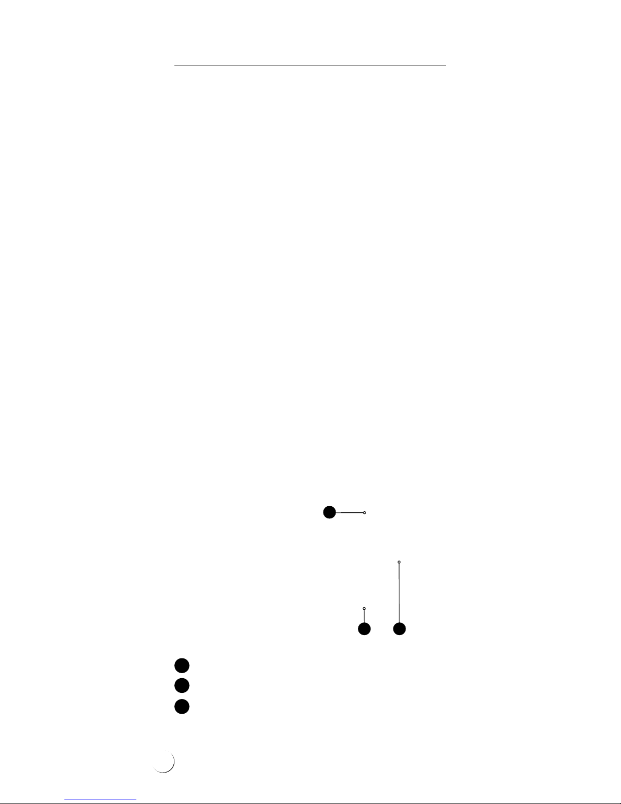
ELEKTRA VCD25 User manual

www.elektra.eu
ELEKTRA
• VCD25
• VCD25/400 V
Heating
Cables
Instrukcja montażu PL
Installation manual UK
Инструкция по монтажу RU


Applications
ELEKTRA VCD25 heating cables are intended for
prevention of snow and ice deposition on:
• driveways, roads, parking spaces and terraces,
• viaducts, bridges, loading ramps,
• stairs.
The heating cables are laid depending on the
type of surface:
• in the layer of sand or dry concrete – for the
asphalt, agstones or paving cobbles surfaces,
• directly in concrete – for the concrete slabs
or reinforced concrete surfaces.
Heat resistant PVC outer sheath
Tinned copper braiding
PET covered aluminum foil shield
XLPE insulation
Multi-wire
heating core
ELEKTRA VCD heating cable structure
3

ELEKTRA
Heating Cables
Characteristics
of the heating cables
• The heating cables are produced
in ready-made units of the following lengths:
ELEKTRA VCD25 from 4.5 up to 142 m,
ELEKTRA VCD25/400 V from 8 up to 250 m,
• The cables are terminated at one end with
a 2.5 m-long power supply conductor,
and a connecting joint at the other,
• Specic heat output: 25 W/m,
• Power supply voltage:
– 230 V, 50/60 Hz for ELEKTRA VCD25,
– 400 V, 50/60 Hz for ELEKTRA VCD25/400 V,
• External dimensions: ≈5 x 7 mm,
• Min. installation temperature: -5°C,
• Min. cable bending radius: 3.5 D,
• Heating cables are screened, and their mains
connection via a residual current device con-
stitutes effective anti-shock protection.
• “cold” power supply conductor
• double-core ELEKTRA VCD heating cable
• connecting joint between the power supply
conductor and the heating cable
1
2
3
1
2 3
4

Single-side powered
heating cables
Self-adhesive label
Note:
VCD25 heating cables are designed for the rated
voltage 230 V, 50 Hz, and VCD25/400 heating
cables – for the rated voltage 400 V, 50 Hz.
Heating cables’ power output may vary with +5%
and -10% from the label values.
!
The label features the following pictograph:
Note:
Never cut the heating cable.
Never trim the heating cable, only the power
supply conductor may be trimmed if required.
Never squash the “cold tail”.
Do not ever undertake on your own any attempts
to repair the heating cables, and in case any
damage is detected, report the damage to
an ELEKTRA authorized installer.
Never stretch or strain the cable excessively,
nor hit it with sharp tools.
Do not install the heating cables when ambient
temperature drops below -5°C.
Never lead the end joint and the connecting joint
between the heating cable and the power supply
conductor out of the surface. Both joints must be
placed - depending on the type of surface - within
the layer of sand, dry concrete or directly in concrete.
!
5

ELEKTRA
Heating Cables
Note:
Heating cables must be installed according
to the Instructions.
Mains connection of the heating cables should
be performed by an authorized electrician.
!
General information
When protecting external areas from snow and
ice deposition, it is required to assess the required
heat output value per m2of the surface. Recom-
mended heat output depends on the regional cli-
mate conditions, i.e. minimum ambient tempera-
ture, snowfall intensity and wind strength.
Higher output is required if the heated area is:
• exposed to low temperatures,
• exposed to wind operation from below:
bridges, stairs, loading ramps, overpasses,
• located in regions of intense snowfall.
Applying insulation layer to the surfaces exposed
to wind operation from below can improve the
effectiveness.
Ambient
temperature
Heat output
[W/m2]
> -5°C
-5°C ÷ -20°C
-20°C ÷ -30°C
< -30°C
200
300
400
500
6

Depending on the cable spacing, it is possible to
obtain required output per m2of the heated area.
Cable spacing cannot drop below 5 cm.
To protect large areas against snow and ice depo-
sition, one option is application of 400 V voltage
heating cables, which would evenly load the elec-
tric circuit. Application of such cables would also
facilitate installation works, limiting the required
number of heating units.
Heat output 25 W/m
[W/m2][cm]
250
300
350
400
500
10
8
~7
~6
5
Controls
Properly selected control system will ensure ade-
quate operation of the system only during snow-
and freezing rainfall. A controller with a tem-
perature and moisture sensor will automatically
recognize the weather conditions. The system will
be then kept on standby and only switched on
when actually necessary. For this purpose, DIN-
bus installed controllers ELEKTRA ETR2 and ETO2
can be applied.
7

ELEKTRA
Heating Cables
Snow & ice protection controls
ELEKTRA ETR2G controller – max. load up to 16
A, total output of installed heating cables must
not exceed 3600 W. As standard, equipped
with one temperature and moisture sensor with
installation tube.
ELEKTRA ETOG2 controller – max. load up to 3x16 A.
For applications in extended heating systems.
As standard, equipped with one temperature and
moisture sensor and an installation tube.
Additional temperature and moisture sensor can
be connected to this controller, which will enable
protection of two outdoor areas. Enables control
of two independent zones, e.g. garage driveway
and gutters, with one controller.
8

To maintain xed positioning of the cable and
steady spacing conforming to the calculated values,
the cables need to be attached with the ELEKTRA
TME installation tape (the tape should be posi-
tioned with the distances of 40 cm) or installation
mesh of 50 mm x 50 mm grid, made of Ø 2 mm
wire.
The heating cable layout should be commenced
from the side of the power supply conductor,
in such a way to enable easy reach to the switch-
board.
If prolonging proved necessary, it is to be made
with a heat shrink joint, ensuring that the con-
nection is safely sealed.
TME installation tape
Installation
Stage 1: Heating cable’s
installation
Before commencing the installation of the sys-
tem, it is required to assess the necessary heat
output per m2, as well as calculate the required
spacing of the heating cable.
In order to calculate the required heating cable’s
spacing, apply the following formula:
a-a=S/L
where:
a-a: distances between cables,
S: surface area, for the surface heated with the heating cable,
L: heating cable’s length
9

ELEKTRA
Heating Cables
Cross section of pavement or driveway made from
agstones or paving cobbles
The heating cable layout will depend from the
surface type.
Asphalt, agstones
or paving cobbles surfaces
Stages of works:
• the hard concrete core base that is covered
with a layer of sand or dry concrete of the
min. 30 mm thickness (min. 50 mm for the
asphalt surfaces), and then compacted,
• ELEKTRA TME installation tapes or installation
mesh are laid on the layer of the compacted
sand or dry concrete, the heating cable faste-
ned to them,
• the cables are completely covered with a layer
of sand or dry concrete,
• the nishing surface works follow – stage 4.
ELEKTRA VCD
heating cable
Compacted
base
Sand
or sand-cement sub-crust
min. 30 mm
Paving cobbles
or flagstones
Temperature
and moisture sensor
in installation tube
10

Example of ELEKTRA VCD25 heating cables as laid
in the garage driveway made from paving cobbles
11

ELEKTRA
Heating Cables
When protecting garage driveways against snow
and ice, it is not necessary to heat the entire
surface, but only the tyre tracks. The temperature
and moisture sensor should be placed within the
heated area, but not directly in the tyre tracks
under the car tyres’ path – in order to avoid snow
accumulation and unnecessary operation of the
heating system.
It is also necessary to heat the oor drain (drain-
age) in order to ensure the outow of water origi-
nating from snow melting. For this, use ELEKTRA
SelfTec®33 self-regulating cable. Place the cable
at the through bottom, enter the cable’s end into
the drainage down to 0.5 m – 1.0 m deep.
The heating circuit should be connected to the
power source in the electric board of the drive-
way, so that it is switched on simultaneously
with the remaining heating circuits.
Driveway Garage
Heating
cable
Linear drainage heating
12

Concrete surfaces
Concrete surfaces require expansion joints.
Unreinforced concrete slabs should be divided
into expanded areas of the surface no larger
than 9 m2, reinforced concrete agstones into
areas no larger than 35 m2. The length of the
heating cables should be selected so that they
do not cross the expansion joints. Only the
power supply conduits (“Cold Tails”) can cross
the expansion joints. The Cold Tails are installed
in a metal protective conduit of the length of
approx. 50 cm.
Unreinforced concrete surfaces
Stages of works:
• the compacted base is levelled,
• ELEKTRA TME installation tapes or installation
mesh are laid on the compacted base,
the heating cable is fastened to them,
• the concrete slab works follow – stage 4.
Cross section of pavement or driveway
made of concrete slab
ELEKTRA VCD
heating cable
Temperature
and moisture sensor
in installation tube
Compacted
base
Concrete slab
min. 50 mm thick
Expansion
joint
13

ELEKTRA
Heating Cables
Reinforced concrete agstones
Heating cables can be fastened to the reinforce-
ment of the ferroconcrete agstones. Alternatively,
the installation mesh of 100 mm x 100 mm grid
made of Ø 4 mm wire can be applied, which
would facilitate maintaining steady spacing of
the cable, conforming to the calculated values.
Applying thermal insulation layer to ferroconcrete
agstone surfaces exposed to wind operation
from below (ramps, bridges, overpasses) can im-
prove the system’s effectiveness.
VCD
heating cable
Roadway layer
(e.g. resin, quartz)
Reinforcement
of the ferr
oconcrete
flagstone
Metal mesh
Layer of plaster,
e.g. acrylic,
on plastering mesh
Thermal
insulation
Cross section of a suspended loading ramp
14

Stairs
Heating cables are laid in steps, placed in dedicated
previously chiseled grooves, and then covered
with concrete. The grooves are optimally made
at the stage of stairs construction. This method
of installation would greatly facilitate later
surface nishing works and would not cause
surface elevation.
If such elevation is acceptable (e.g. in any al-
ready existing stairs), then the cables will be
placed directly on the steps and xed to their
surface with the ELEKTRA TME installation tape
or installation mesh.
As substeps are not heated, outermost segments
of the cable need to be positioned as close to
the step’s edge as possible.
15

ELEKTRA
Heating Cables
Example of the heating cable layout on the steps
Laying thermal insulation on the steps and land-
ings of the stairs will increase efciency (by short-
ening the warm-up time), which will decrease the
system’s operation costs.
80 mm
80 mm
80 mm
16

Stage 2: After the heating
cable has been laid
At this stage, it is necessary to undertake the
following steps:
• stick into the Warranty Card the self-adhesive
label, positioned on the power supply con-
ductor of the heating cable,
• in the Warranty Card, prepare asketch of the
heating cable’s layout positioning,
• fed the power supply conductor of the heat-
ing cable into the switchboard,
• perform the measurements of:
- heating wire resistance,
- insulation resistance.
The measurement results of the heating
core’s resistance should not vary from the
one given on the label with more than -5%
a n d +10 % .
The insulation’s resistance for the heating
cable, as measured with a tool of the rated
voltage 1000 V (e.g. megaohmmeter), should
not be below 10 MΩ. Enter the results into
the Warranty Card.
When the surface has been nished, repeat
the measurements and compare the results
to ensure that the heating cable has not been
damaged while surface installation works.
17

ELEKTRA
Heating Cables
(brown
or black)
(yellow-green)
Power supply conductors
Ohmmeter
Megaohmmeter
(brown
or black)
(blue)
Heating wire’s resistance measurement
Insulation resistance measurement
18

Stage 3: Temperature and
moisture sensor’s
installation
preparation
• establish the optimal positioning for the tem-
perature and moisture sensor – aplace which
would be especially vulnerable to prolonged
low temperatures and increased moisture
deposition (e.g. in ashade or exposed to
wind operation) – place here the installation
tube of the sensor on the prepared hardened
base,
• feed the protective conduit with the so called
“draw wire” from the installation tube to
the switchboard (after the surface has been
completed, the protective pipe will enable
feeding the temperature and moisture sen-
sor’s wire),
In case of asignicant sensor’s distance from
the switchboard, or bending of the protective
conduit, it is necessary to:
• install an additional sealed electric box “on
the way” to the board, or
• install the protective conduit with atwisted
pair screened control cable, min. 3-pair (e.g.
LIYCY-P 3x2x1,5) – the sensor’s wire with the
control cable is to be connected with aheat
shrink joint.
Note:
The protective conduit should be run
in such away to enable the future exchange
of the temperature and moisture sensor,
if required.
!
19

ELEKTRA
Heating Cables
Stage 5: Temperature and
moisture sensor’s
installation
The temperature and moisture sensor should be
installed in the installation tube after the sur-
face has been completed. Then, the sensor’s wire
should be fed into the protective conduit installed
before the surface has been completed, with the
so called “draw wire”. Under the sensor, the wire
excess should be deposited (min. 30 cm) for the
future sensor replacement, if required.
Ground temperature and moisture sensor ETOG-56T with
installation tube (for soil, concrete agstones, paving
cobbles etc.) can be used for heating control of drive-
ways, trafc routes, etc.
Stage 4: Finishing
surface works
During surface works, level the installation
tube, so that it is positioned 5 mm below the
level of the surface. Due to this, the water will
be deposited on the temperature and moisture
sensor.
20
Other manuals for VCD25
1
This manual suits for next models
1
Table of contents
Languages:
Other ELEKTRA Cables And Connectors manuals

ELEKTRA
ELEKTRA VCDR User manual

ELEKTRA
ELEKTRA SelfTec PRO Series User manual

ELEKTRA
ELEKTRA FreezeTec Series User manual

ELEKTRA
ELEKTRA TuffTec 30 User manual

ELEKTRA
ELEKTRA VCD25 User manual

ELEKTRA
ELEKTRA VCD7 User manual

ELEKTRA
ELEKTRA TuffTec 30 User manual

ELEKTRA
ELEKTRA SelfTec DW User manual

ELEKTRA
ELEKTRA Selftec User manual

ELEKTRA
ELEKTRA VCD10 User manual