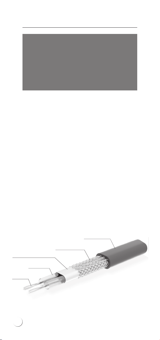
ELEKTRA VCD25 User manual

www.elektra.eu
ELEKTRA
•VCD25 Heating Cables
Snow&Ice
Protection
Installation manual

ELEKTRA
Heating Cables
Applications
ELEKTRA VCD25 heating cables are intended for
prevention of snow and ice deposition on:
• driveways, roads, parking spaces and terraces,
• viaducts, bridges, loading ramps,
• stairs.
The heating cables are laid depending on the
type of surface:
• in the layer of sand or dry concrete – for the
asphalt, agstoned or paving cobbles surfaces,
• directly in concrete – for the concrete slabs
or reinforced concrete surfaces.
For the proper installation and operation of the
ELEKTRA snow melting system, it is recommended
to rst read this Installation Manual.
The heating cables should be installed in accor-
dance with NFPA 70, National Electrical Code
(NEC), Article 424 and Canadian Electrical Code,
Part I(CEC), C22.2-09, Section 62.
LS0H outer sheath
Tinned copper braiding
PET covered aluminum foil shield
XLPE insulation
Multi-wire
heating core
ELEKTRA VCD heating cable structure
2

Characteristics
Heating cables are manufactured as ready-
made units, suitable for direct installation.
Composed of single-side power supplied
heating cables.
• The ELEKTRA VCD25 heating cables are
produced in ready-made units of the lengths
from 20 ft (6 m) up to 731 ft (223 m).
• The heating cables are connected to a 8 ft
(2.5 m) -long power supply conductor and
terminated at the end.
• Specic heat output: 7.5 W/ft (25 W/m).
• Power supply voltage:
– 240VAC 60 Hz-rated, supplied from an elec-
trical panel with 240 VAC electrical circuit.
• External dimensions: ~1/5 x 1/3 in (5.5 x 9.0
mm).
• Min. installation temperature: 23°F (-5°C).
• Min. cable bending radius: 3.5 D.
• The heating cables are shielded and power
supply connection requires GFEP.
Caution:
The heating cables cannot contact combustible
surfaces.
!
3

ELEKTRA
Heating Cables
• “cold” power supply conductor
• double-core ELEKTRA VCD heating cable
• connecting joint between the power supply
conductor and the heating cable
• nameplates sticker
1
2
3
1
2 3
Note:
The power output of the heating cable can vary
+5, –10% from the provided rated specications.
!
Cold tail marking
240 V – red outer jacket or red label with 240 V
printing
4
4
4

Single-side powered
heating cables
The cables nameplates sticker always show the
rated voltage for each heating cable.
Note:
Never bend the joint and end seal.
Never cut the heating cable.
Never trim the heating cable, only the power
supply conductor may be trimmed if required.
Never squash the “cold tail”.
Do not ever undertake on your own any attempts
to repair the heating cables, and in case any
damage is detected, report the damage to
an ELEKTRA authorized installer.
Never stretch or strain the cable excessively,
nor hit it with sharp tools.
Do not install the heating cables when ambient
temperature drops below 23°F (-5°C).
!
The label features the following pictograph:
IPX7
CODE:
DATE: week/year
HEATING CABLE FOR OUTDOOR APPLICATIONS
SNOW & ICE PROTECTION
Model: VCD 25/150 240VAC
240 VAC 0.6A 384.0 ohm
7.5 W/ft (25 W/m) 150W
19.7 ft (6.0 m)
REFER TO INSTALLATION INSTRUCTIONS
CAUTION: a ground fault protection device must
be used with heating device
ATTENTION: ce produit doit etre utilise avec une
protection de mise a la terre
Minimum instalationtemperature 23°F (-5°C)
_ _ _ _ _ _ _ _ _ _ _ _ _ _ _ _ _ _ _ _ _ _
5906726706460
Self-adhesive label
5

ELEKTRA
Heating Cables
Note:
Heating cables must be installed according
to the Instructions.
Mains connection of the heating cables should
be performed by an authorized electrician.
!
General information
When protecting external areas from snow and
ice deposition, it is required to assess the required
heat output value per ft2(m2) of the surface.
Recommended heat output depends on the
regional climate conditions, i.e. minimum
ambient temperature, snowfall intensity
and wind strength.
The output higher than 28 W/ft² (300 W/m²) is re-
quired if the heated area is:
• exposed to low temperatures,
• exposed to wind operation from below:
bridges, stairs, loading ramps, overpasses
• located in regions of intense snowfall.
Ambient
temperature
Heat output
W/ft2(W/m2)
> 23°F (-5°C)
23°F (-5°C)÷-4°F (-20°C)
-4°F (-20°C)÷-22°F (-30°C)
< -22°F (-30°C)
19 W/ft² (200 W/m²)
28 W/ft² (300 W/m²)
37 W/ft² (400 W/m²)
47 W/ft² (500 W/m²)
Applying insulation layer to the surfaces exposed
to wind operation from below can improve the
effectiveness.
6

Snow & ice protection controls
ELEKTRA ETOG2 controller – max. load up to 3x16 A.
For applications in extended heating systems.
As standard, equipped with one temperature and
moisture sensor and an installation tube.
Heating power Cable spacing
W/ft2(W/m2)inch (cm)
23 (250) ~ 4.0 (10)
28 (300) ~ 3.2 (8)
33 (350) ~ 2.8 (7)
37 (400) ~ 2.5 (6)
47 (500) ~ 2.0 (5)
Controls
A properly selected control system will ensure
adequate operation of the system only during
snow and freezing rainfall. A temperature
controller with a temperature and moisture
sensor will automatically recognize the weather
conditions.
The heating system will be then kept on standby
and only switched on when actually necessary.
For this purpose, DIN-bus installed controllers
ELEKTRA ETO2 can be utilised.
Depending on the cable spacing, it is possible to
obtain required output per ft2(m2) of the heated
area.
Cable spacing cannot drop below 2” (5 cm).
7

ELEKTRA
Heating Cables
Installation
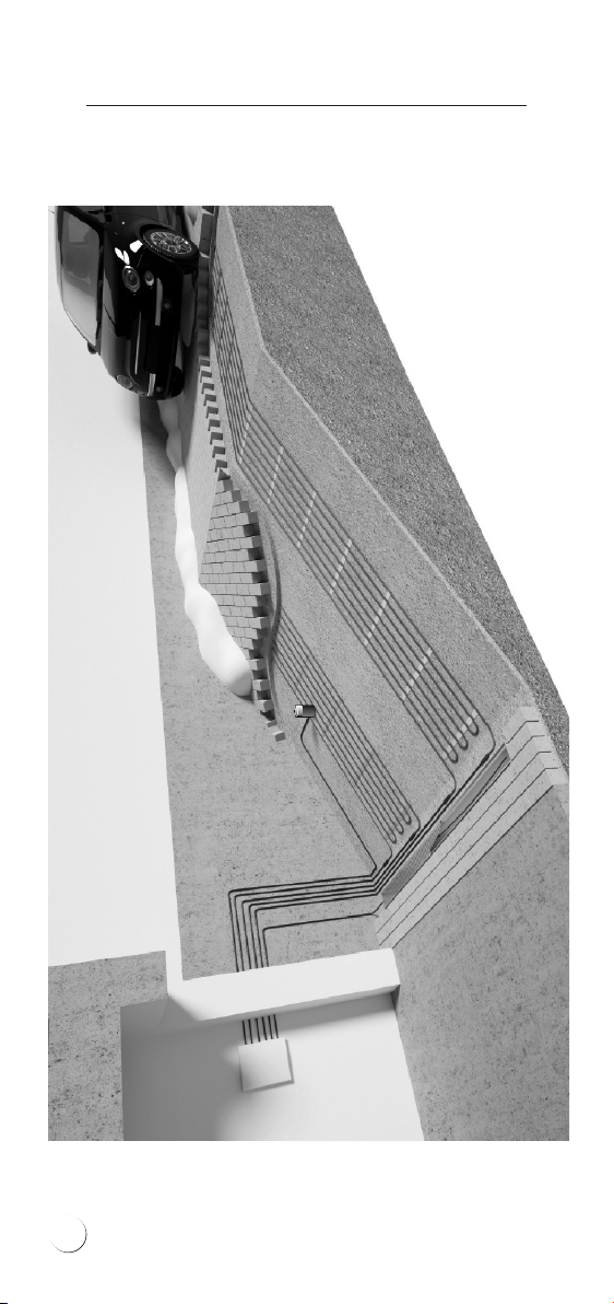
Stage 1: Heating cable’s
installation
Before commencing the installation of the sys-
tem, it is required to assess the necessary heat
output per ft2(m2), as well as calculate the re-
quired spacing of the heating cable.
In order to calculate the required heating cable’s
spacing, apply the following formula:
a-a=S/L
where:
a-a: distances between cables,
S: surface area, for the surface heated with the heating cable,
L: heating cable’s length
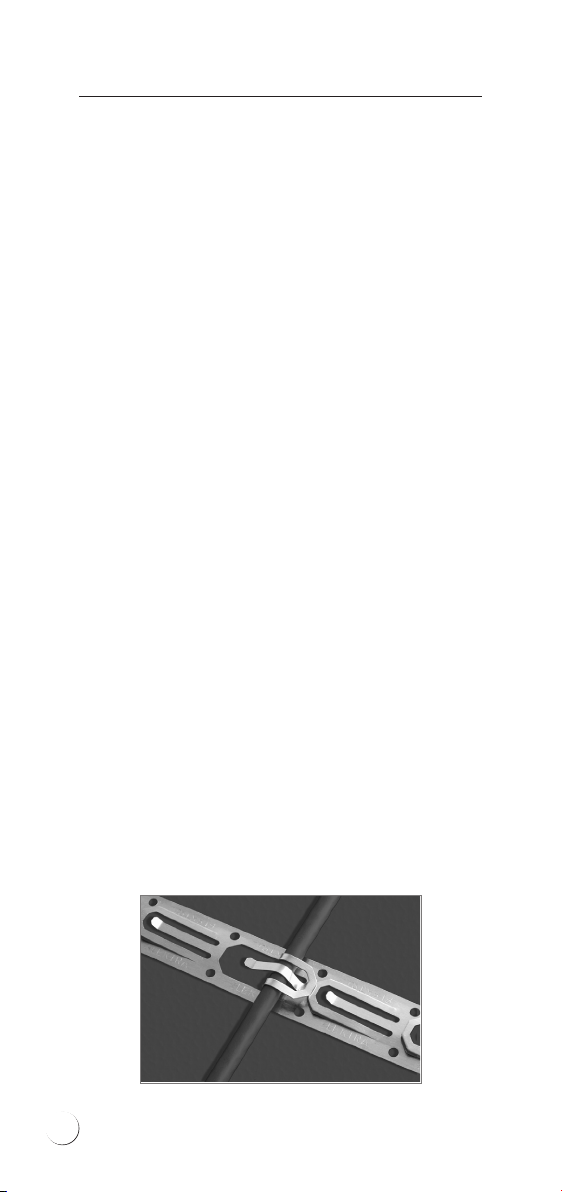
To maintain xed positioning of the cable and
steady spacing conforming to the calculated
values, the cables need to be attached with the
ELEKTRA TME installation tape (the tape should
be positioned with the distances of 40 cm) or in-
stallation mesh of 2” x 2” (50 mm x 50 mm) grid,
made of Ø 0.08” (Ø 2 mm) wire.
TME installation tape
Additional temperature and moisture sensor can
be connected to this controller, which will enable
protection of two outdoor areas. Enables control
of two independent zones, e.g. garage driveway
and gutters, with one controller.
8

The heating cable layout should be commenced
from the side of the power supply conductor,
in such a way to enable easy reach to the switch-
board.
If prolonging proved necessary, it is to be made
with a heat shrink joint, ensuring that the con-
nection is safely sealed.
The heating cable layout will depend from the
surface type.
Asphalt, agstoned
or paving cobbles surfaces
Stages of works:
• the hard concrete core base that is covered
with a layer of sand or dry concrete of the
min. 1.2” (30 mm) thickness min. 2” (50 mm)
for the asphalt surfaces, and then compac-
ted,
• ELEKTRA TME installation tapes or installa-
tion mesh are laid on the layer of the com-
pacted sand or dry concrete, the heating
cable fastened to them,
• the cables are completely covered with a
layer of sand or dry concrete,
• the nishing surface works follow – stage 4.
Crosssection of a driveway made of asphalt or paving blocks
(installation in a layer of sand bedding)
Hard core
base
Asphalt or
stone surfaces
Heating mat
or heating
cable
Temperature and
moisture sensor
in installation tube
Sand or sand-cement
sub-crust
min. 1.2'' (30 mm) stone
or min. 2.0'' (50 mm) asphalt
Przekrój podjazdu wykonanego z asfaltu lub kostki brukowej
(montaż w warstwie podsypki piaskowej)
podkład
utwardzony
kostka brukowa,
płyty lub asfalt
mata lub przewód
grzejny ELEKTRA
czujnik temperatury
i wilgoci w tulei
montażowej
piasek lub podsypka
piaskowo-cementowa
min. 3 cm (kamień)
lub min. 5 cm (asfalt)
Cross section of driveway made of asphalt or paving blocks
(installation in a layer of sand bedding)
9

ELEKTRA
Heating Cables
Example of ELEKTRA VCD25 heating cables as laid
in the garage driveway made from paving cobbles
10

Linear drainage heating
When protecting garage driveways against snow
and ice, it is not necessary to heat the entire
surface, but only the tyre tracks. The temperature
and moisture sensor should be placed within the
heated area, but not directly in the tyre tracks
under the car tyres’ path – in order to avoid snow
accumulation and unnecessary operation of the
heating system.
Linear drainage’s
heating cable
Driveway Garage
11

ELEKTRA
Heating Cables
It is also necessary to heat the oor drain (drain-
age) in order to ensure the outow of water origi-
nating from snow melting. For this, use ELEKTRA
VCD25 heating cable as well.
The heating circuit should be connected to the
power source in the electric board of the drive-
way, so that it is switched on simultaneously
with the remaining heating circuits.
Concrete surfaces
Concrete surfaces require expansion joints.
Unreinforced concrete slabs should be divided
into expanded areas of the surface no larger than
100 ft2 (9 m2), reinforced concrete agstones into
areas no larger than 375 ft2 (35 m2). The length
of the heating cables should be selected so that
they do not cross the expansion joints. Only the
power supply conduits (“Cold Tails”) can cross
the expansion joints. The Cold Tails are installed
in a metal protective conduit of the length of
approx. 7.75” (50 cm).
Unreinforced concrete surfaces
Stages of works:
• the compacted base is levelled,
• ELEKTRA TME installation tapes or installation
mesh are laid on the compacted base,
the heating cable is fastened to them,
• the concrete slab works follow – stage 4.
12

ELEKTRA VCD
heating cable
Roadway layer
(e.g. resin, quartz)
Reinforcement
of the f
erroconcrete
agstone
Metal mesh
Layer of plaster,
e.g. acrylic,
on plastering mesh
Thermal
insulation
Cross section of a suspended loading ramp
Reinforced concrete agstones
Heating cables can be fastened to the reinforce-
ment of the ferroconcrete agstones. Alternatively,
the installation mesh of 4” x 4” (100 mm x 100
mm) grid made of Ø 0.16” (4 mm) wire can be
applied, which would facilitate maintaining
steady spacing of the cable, conforming to the
calculated values.
Applying thermal insulation layer to ferroconcrete
agstone surfaces exposed to wind operation
from below (ramps, bridges, overpasses) can
improve the system’s effectiveness.
ELEKTRA VCD
heating cable
Temperature
and moisture sensor
in installation tube
Compacted
base
Concrete slab
2.0" (50 mm) thick
Expansion
joint
Cross section of pavement or driveway
made of concrete slab
Caution:
VCD25 heating cables must never be run through
an expansion joint.
!
13

ELEKTRA
Heating Cables
Stairs
Heating cables are laid in steps, placed in dedicated
previously chiseled grooves, and then covered
with concrete. The grooves are optimally made
at the stage of stairs construction. This method
of installation would greatly facilitate later
surface nishing works and would not cause
surface elevation.
If such elevation is acceptable (e.g. in any al-
ready existing stairs), then the cables will be
placed directly on the steps and xed to their
surface with the ELEKTRA TME installation tape
or installation mesh.
As substeps are not heated, outermost segments
of the cable need to be positioned as close to
the step’s edge as possible.
14

Example of the heating cable layout on the steps
3” (75 mm)
Laying thermal insulation on the steps and land-
ings of the stairs will increase efciency (by short-
ening the warm-up time), which will decrease the
system’s operation costs.
3” (75 mm)
3” (75 mm)
3” (75 mm)
15

ELEKTRA
Heating Cables
Stage 2: After the heating
cable has been laid
At this stage, it is necessary to undertake the
following steps:
• stick into the Warranty Card the self-adhesive
label, positioned on the power supply con-
ductor of the heating cable,
• in the Warranty Card, prepare asketch of the
heating cable’s layout positioning,
• fed the power supply conductor of the heat-
ing cable into the switchboard,
• perform the measurements of:
- heating wire resistance,
- insulation resistance.
The measurement results of the heating
core’s resistance should not vary from the
one given on the label with more than -5%
and +10%.
The insulation’s resistance for the heating
cable, as measured with a tool of the rated
voltage 1000 V (e.g. megaohmmeter), should
not be below 50 MΩ. Enter the results into
the Warranty Card.
When the surface has been nished, repeat
the measurements and compare the results
to ensure that the heating cable has not been
damaged while surface installation works.
Note:
In case of planned delay in connection of the
heating cable to the electrical installation, seal the
power supply cable of the heating cable against
the possibility of internal moisture penetration
using a protective cap placed on the conduit or
a heat shrinkable end cap.
!
16

(black 1)
(yellow-green)
Power supply conductors
Ohmmeter
Megaohmmeter
(black 1)
(black 2)
Heating wire’s resistance measurement
Insulation resistance measurement
17

ELEKTRA
Heating Cables
• establish the optimal positioning for the tem-
perature and moisture sensor – aplace which
would be especially vulnerable to prolonged
low temperatures and increased moisture
deposition (e.g. in ashade or exposed to
wind operation) – place here the installation
tube of the sensor on the prepared hardened
base,
• feed the protective conduit with the so called
“draw wire” from the installation tube to
the switchboard (after the surface has been
completed, the protective pipe will enable
feeding the temperature and moisture sen-
sor’s wire),
In case of asignicant sensor’s distance from
the switchboard, or bending of the protective
conduit, it is necessary to:
• install an additional sealed electric box “on
the way” to the board, or
• install the protective conduit with atwisted
pair screened control cable, min. 3-pair
– the sensor’s wire with the control cable is
to be connected with aheat shrink joint.
Stage 3: Temperature and
moisture sensor’s
installation
preparation
Note:
The protective conduit should be run
in such away to enable the future exchange
of the temperature and moisture sensor,
if required.
!
18

Stage 5: Temperature and
moisture sensor’s
installation
The temperature and moisture sensor should be
installed in the installation tube after the sur-
face has been completed. Then, the sensor’s wire
should be fed into the protective conduit installed
before the surface has been completed, with the
so called “draw wire”. Under the sensor, the wire
excess should be deposited min. 1 ft (30 cm) for
the future sensor replacement, if required.
The sensor should be positioned approx. 0.2” (5 mm)
below the surface level to enable water deposition
on the sensor. After the sensor has been levelled, ll
the vacant space e.g. with concrete.
Stage 4: Finishing
surface works
During surface works, level the installation
tube, so that it is positioned 0.2” (5 mm) below
the level of the surface. Due to this, the water
will be deposited on the temperature and mois-
ture sensor.
Ground temperature and moisture sensor ETOG-56T with
installation tube (for soil, concrete agstones, paving
cobbles etc.) can be used for heating control of drive-
ways, trafc routes, etc.
19

ELEKTRA
Heating Cables
sensor
protective
conduit
sensor’s wire laid with
approx. 1ft (30 cm)excess
ller
e.g. concrete
surface
compacted base
under the surface
installation tube
0.2” (5 mm)
Stage 6: Temperature
controller’s installation
The heating cable connection to the domestic
electric circuit should be performed by an author-
ised electrician.
The connection of the:
1. mains,
2. power supply conductors of the heating cable,
3. temperature sensor
should be executed according to the diagram
included in the temperature controller’s Instructions.
Example of temperature and moisture sensor’s
installation in the surface
20
Other manuals for VCD25
1
Table of contents
Other ELEKTRA Cables And Connectors manuals

ELEKTRA
ELEKTRA VCD7 User manual

ELEKTRA
ELEKTRA SelfTec PRO Series User manual

ELEKTRA
ELEKTRA Selftec User manual

ELEKTRA
ELEKTRA SelfTec DW User manual

ELEKTRA
ELEKTRA SelfTec 16 User manual

ELEKTRA
ELEKTRA VCDR User manual

ELEKTRA
ELEKTRA VCD10 User manual

ELEKTRA
ELEKTRA SelfTec16 ready2heat User manual

ELEKTRA
ELEKTRA TuffTec 30 User manual

ELEKTRA
ELEKTRA FreezeTec Series User manual