Elektromaten TS 981 User manual

Electrical operating instructions
Door control panel TS 981
Software 2.6 (Design and functions subject to change)
51171314 -l 02.2013
en

Page 2
Page
OPERATING INSTRUCTIONS
SAFETY DIRECTIONS.................................................................................................4
INSTALLATION ADVICE ..............................................................................................6
INSTALLATION OVERVIEW ........................................................................................7
ENCLOSURE INSTALLATION ....................................................................................8
CONNECTING THE CONTROL AND THE ELEKTROMATEN®..........................................................8
MAINS SUPPLY............................................................................................................9
PHASE ROTATION.......................................................................................................10
MOTOR CONNECTION (internal wiring) ....................................................................10
RAPID ADJUSTMENT OF THE LIMITS.......................................................................11
HARDWARE OVERVIEW.............................................................................................12
WIRING DIAGRAM .......................................................................................................14
CONTROL PROGRAMMING........................................................................................18
Operatingmode.............................................................................................................19
Door position .................................................................................................................19
Functions .......................................................................................................................20
Safetyfunctions..............................................................................................................21
SettingsonlyforELEKTROMATEN®withdirect/frequency inverterDU/FI ......................23
Extendeddoorfunctions.................................................................................................24
Maintenancecyclecounter .............................................................................................25
MEMORY CHECK ........................................................................................................25
RESET..........................................................................................................................26
SOFTWARE..................................................................................................................26
SAFETY DEVICES .......................................................................................................27
DoorsafetyswitchX2 ....................................................................................................27
Safetyedgesystemwithoptionalconnectionforshutterpass-doororslackwireswitchcontact.X2 ...27
Typ1: Resistanceevaluation 1K2 with normally closed safety edge contact...................27
Typ2: Resistanceevaluation 8K2 with normally opensafetyedgecontact .....................28
Typ3: Opticalsafety edge (Vitector) ..............................................................................28
Mountingthespiralcable................................................................................................28
Functionofthesafetyedgesystem.................................................................................29

Page 3
Page
Pass door / slack rope switch input X2 ...........................................................................30
Emergency stop X3.......................................................................................................30
FUNCTION DESCRIPTION..........................................................................................31
Internalpushbutton/Threepush button / Key switch X5 / X15.......................................31
Automaticclosing...........................................................................................................31
Automaticclosinginterruption.........................................................................................31
Through/Reflectivephoto cell X6 / X16 or Light curtain X6 ............................................32
Ceiling pull switch / Radio control X7 / X17 ....................................................................34
Key switch – intermediate stop X8 ................................................................................34
Keyswitch(latching)interruptautomaticclosingX11 ......................................................35
Smokedraining - Function (RWA) X12 ..........................................................................35
Lightindicatorfortraffic control X13 ...............................................................................35
SafetyagainstentrampmentX18 ...................................................................................37
Potentialfree changeover contact X20 /X21 .................................................................37
Overruncorrection..........................................................................................................37
Dooroverloadmonitor ...................................................................................................38
AIRlook SLF..................................................................................................................39
StatusmonitoringfunctionSMF ......................................................................................39
Maintenancecyclecounter .............................................................................................39
SoftwareUpdate ............................................................................................................40
Shortcircuit/overloadmonitor .......................................................................................40
OPERATING STATUS DISPLAY ..................................................................................41
TECHNICAL DATA.......................................................................................................46
LIFETIME / DOORCYKLES..........................................................................................47
DECLARATION OF INCORPORATION .......................................................................48
FUNCTION OVERVIEW ...............................................................................................49

Page 4
SAFETY DIRECTIONS
Safety Regulations
During the installation, initial operation, maintenance and testing of the Control Panel, it is
necessary to observe the safety and accident-prevention regulations valid for the specific
application.
In particular, you should observe the following regulations (this list is not exhaustive):
European normative
- EN 12445
Safety in use of power operated doors - Test methods
- EN 12453
Safety in use of power operated doors - Requirements
-EN 12978
Industrial, commercial and garage doors and gates -
Safety devices for power operated doors - Requirements and Test methods
Please check normative´s bellow.
VDE-regulations
- EN 418
Safety machinery
Emergency stop equipment functional aspects
Principles for design
- EN 60204-1 / VDE 0113-1
Safety of machinery - Electrical equipment of machines - Part 1:
Prescriptions générales
- EN 60335-1 / VDE 0700-1
Safety of household and similar electrical appliances - Part 1:
General requirements
Basic Directions
This control has been built in accordance with EN 12453 Industrial, commercial and garage
doors and gates - Safety in use of power operated doors - Requirements and EN
12978 Industrial, commercial and garage doors and gates - Safety devices for power
operated doors - Requirements and Test methods; and leftthe factory in perfect condition
fromthepointofviewofsafety. Tomaintainthisconditionand toensuresafeoperation,the user
mustobserveallthedirectionsandwarningscontainedintheseoperating instructions.
Inprinciple,onlytrainedelectricalcraftsmenshouldworkonelectricalequipment.Theymustassess
the work which has been assigned to them, identify potential danger sources and take suitable
safetyprecautions.
Reconstructionoforchangesto TS 981areonlypermissiblewiththeapprovalofthemanufacturer.
Original replacement parts and accessories authorised by the manufacturer guarantee safety.
Liability ceases to apply if other parts are used.
The operational safety of an TS 981 is only guaranteed if it is used in accordance with the
regulations. The limiting values stated in the technical data should not be exceeded under any
circumstances (see corresponding sections of the operating instructions).
Regulations
- Please ensure that the local regulations relating to the Safety of Opera-
tions of Doors are followed

Page 5
SAFETY DIRECTIONS
Explanation of warnings
These operating instructions contain directions which are important for using the ELEKTRO-
MATEN®appropriately and safely.
The individual directions have the following meaning:
DANGER
This indicates danger to the life and health of the user if the appropriate
precautions are not taken.
Please observe the safety and accident prevention regulations valid for
the specific application.
The ELEKTROMATEN®must be installed with the authorised coverings
and protective devices. Care should be taken that any seals are fitted
correctly and screw couplings are tightened correctly.
In the case of ELEKTROMATEN®with a permanent mains connection, an
all-pole main switch with appropriate back-up fuse must be provided.
Check live cables and conductors regularly for insulation faults or
breakages. When a fault is detected in the cabling, the defective cabling
should be replaced after immediately switching off the mains supply.
Before starting operation, check whether the permissible mains voltage
range of the devices corresponds to the local mains voltage.
With three – phase motor connection it must have right phase rotation
The following warnings are to be understood as a general guideline for working with the
ELEKTROMATEN®in conjunction with other devices. These directions must be observed
strictly during installation and operation.
General warnings and safety precautions
CAUTION
This warns that the ELEKTROMATEN®or other materials may be damaged if
the appropriate precautions are not taken.
Check that all screw connections are secure before operating the control
and adjusting the limit switches.

Page 6
INSTALLATION ADVICE
After the ELEKTROMATEN®is fitted we recommend the following procedure to rapidly reach
a fully functioning door.
• Installation Enclosure installation page 8
• Installation Wiring the Drive to the Control page 8
• Check Mains supply page 9
• Check Phase rotation page 10
• Programming Rapid limit adjustment page 11
The door is ready to work in Dead man mode.
• Installation Safety devices page 14, 27
• Programming Door functions page 18
The door is ready to work in automatic mode.
Check connection of external devices e.g. push button etc.
Overview to connect external devices see diagram (page 14-17).
After the devices are connected the programming of the control panel must be finalised.
(page 18).

Page 7
INSTALLATION OVERVIEW
Mains supply
Photo-beam
Pull switch
Three push button
Key switch (latching) interrupt
automatic closing
Emergency stop
Key switch (latching) inter-
mediate stop
Red / Green Traffic- Light
Connection cable ELEKTROMAT®for
Motor and DES ( electronic limit) 11
5
5
3
5
3
3
3
2x4
Spiral cable for
Safety edge system 4
( ) Number of cores in the cable
Important!
Using the connection cable out side the building is not permitted.
Page 8
3
2
1
4
PE
- 14 -
5 -
6 -
- 2
- 3
PIN
1
2
PE
3
4
- 4
- 5
- 6
2 -
PIN
ENCLOSURE INSTALLATION
Beforemountingtheenclosure,thesurfacehastobecheckedforflatness,slopeandfreedom
from vibrations. Mounting must be vertical. It is important that the door can be clearly seen
from the position of the control through-out its travel.
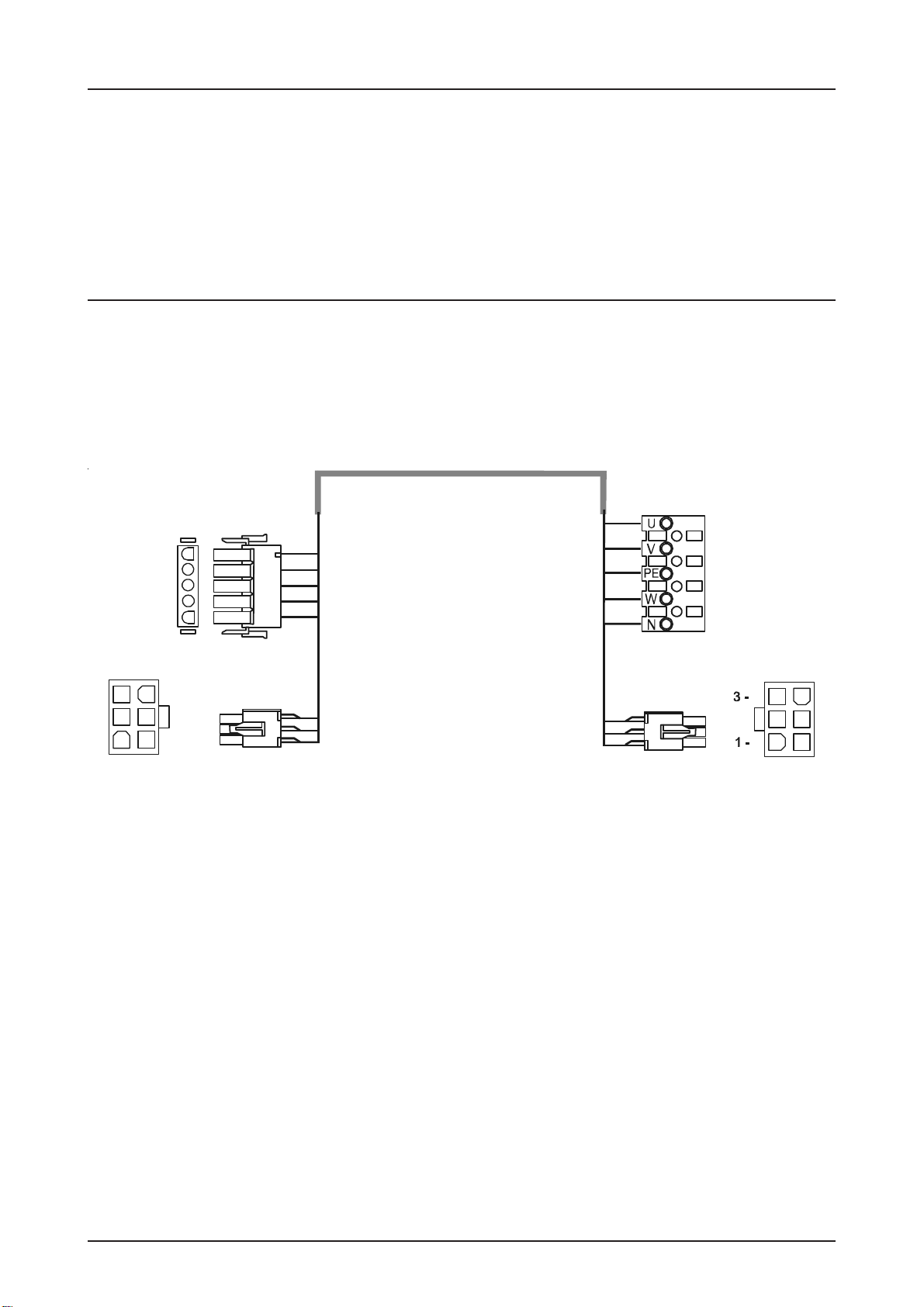
CONNECTING THE CONTROL AND THE ELEKTROMATEN®
After the drive and control are fitted they can be connected with a plug-in cable. The cable
has plugs on each end and for easy fitting. The plugs for motor and control panel are different
and cannot be interchanged.
Connection cable for
digital limit (DES)
Control panel TS 981 ELEKTROMAT®
Cable identification
Motor plug to control unit
PIN -Wire-No. Excution:
1 - 3 Phase W
2 - 2 Phase V
3 - 1 Phase U
4 - 4 Neutral (N) (not used)
5 - PE Earth
Limit plug-in to control panel TS 981 (DES)
PIN - Wire-No. Excution:
1 - 5 Safety chain 24V DC
2 - 6 RS485 B
3 - 7 GND
4 - 8 RS485 A
5 - 9 Safety chain
6 - 10 8V DC
Motor plug-in
Motorconnection (MOT)

Page 9
TheControlpanelTS981hasauniversal electric supplyandworkswiththefollowingsupplies.
(See diagram Fig.1-5)
The supply disconnect device (Main switch or CEE plug) must be installed between 0,6m
and 1,7m above floor level.
Mains supply terminal
Fig.: 1
Fig.: 2
Fig.: 3
Fig.: 5
Fig.: 4
asymmetricwinding
symmetricwinding
MAINS SUPPLY
External fuse!
Control must be saved against short circuit and overload by an external fuse,
max.10Adelayed, in the mains supply.Anautomatic cut offswitchisrequired,
regarding the supply for three-phase or single-phase.
Whenconnectingcontrol tomainssupplya mainsisolatorswitchor(16ACEE–plug)according
EN 12453 is required. The control panel has an integrated auto controlled power unit for
voltages from 230V up to 400V +/- 10%.
DU = 3x400V
FI 1,5KW = 1x230V/N/PE or 3x400V/N/PE
FI 4,5 kW = 3x400V/PE or 3x400V/N/PE
DANGER! To the life and health through electric shock.
IfaGfAfrequencydriveFIisinstalled,itmust be used a class B earth-leakage
circuitbreakerinthemainssupply.Otherswitchescanfailandswitching
unintentionally.

Page 10
PHASE ROTATION
DANGER! To the life and health through electric shock.
Before changing phase rotation the mains supply must be switched OFF.
Three-phase 3 x 400VAC, N, PE
Star connection Three-phase 3 x 230VAC, PE
Delta connection
Single-phase 1 x 230VAC, N, PE
symmetrical winding Single-phase 1 x 230VAC, N, PE
asymmetrical winding
Important note!
For3x400VACPEno
neutral, the brake
rectifier must be
connected between
terminal V and star-
point terminal.
brown brown
supply for
brake
rectifier
blue supply for
brake
rectifier
MOTOR CONNECTION (internal wiring)
blue
On several ELEKTROMATEN®the connection U1 und V1 on the motor-plug are
interchanged.
Important Notice!
Afterthemainssupplyhas been connected: toconfirmthatthephaserotationof
theelectricalmotoriscorrectthedoorshallmoveUPWARDS if the OPEN push
buttonisoperated.Ifthedoordoesnot OPEN change first phase rotation.
Forallthree phase ELEKTROMATEN® even DU: Change wiring atterminalX1:1.1–1.2.
Forinverterdrives FI-ELEKTROMATEN®seepage13.
ForallsinglephaseELEKTROMATEN®:Changewiringattheconnectioncableplug,
changecoreno.1+3reciprocal.
Page 11
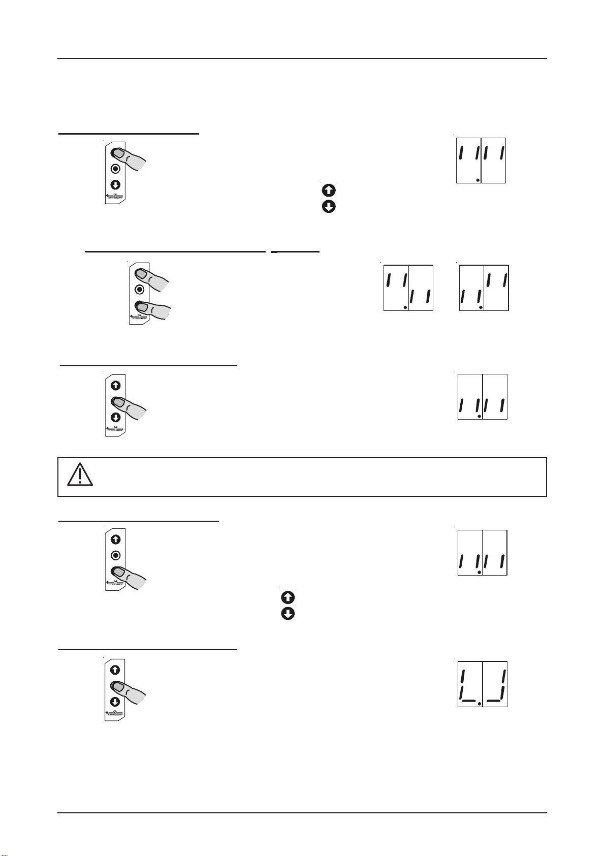
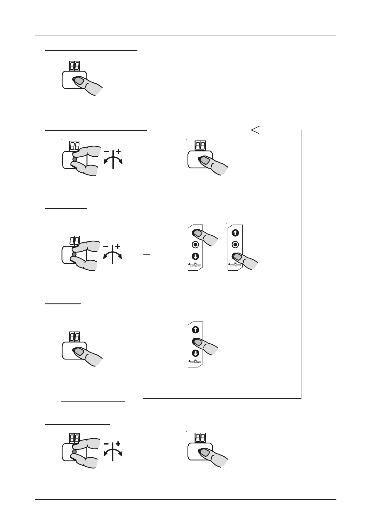
RAPID ADJUSTMENT OF THE LIMITS
The Rapid adjustment is finished
The door could be moved in DEADMAN mode UP/DOWN
Further adjustments see programming mode
1. Setting final limit open
pressbuttontoreachupperlimit
Door open
Display
blinking
2. Memorise the final limit open
Pressstop-buttonfor3sec.until
thedisplaychanges Display
changes
3.Setting the final limit close
press button to reach lower limit Display
blinking
Door close
4. Memorise the final limit close
Pressstop-buttonfor3sec.until
thedisplaychanges Display
changes
When the phase rotation has been checked the Rapid limit adjustment can be made.
The final setting can be made with the fine adjustment (Control Programming page 19).
Safety limits and pre-limits are automatically adjusted.
ThefinallimitOPEN ismemorisedwhenthedoor movesforatleastone secondfrom
closeintotheupper limit position.
1a. Reversing FI-ELEKTROMAT®rotation
Toreversethemotorrotation
keepbothbuttonspressedfor
threesecondsuntilthedisplay
changes Display
blinking Display
changes
Page 12
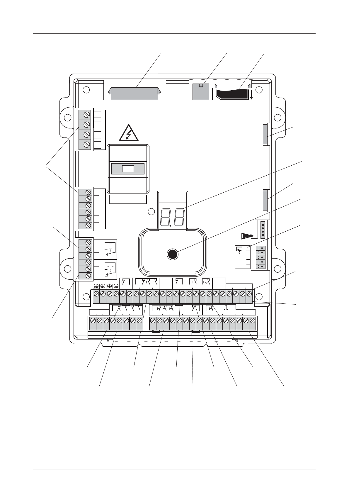
HARDWARE OVERVIEW
X1
X21
X3
X2
X13 X16
X6 X7
X18
S1
V1
X8
X11
X12
X17
X5
X20
X15
SMF
SLF
MOT DES MMC/SD
20.1
20.2
20.3
21.1
21.2
21.3
1.8
1.8
1.8
1.9
1.9
1.9
1.1
1.2
1.3
1.4
F1 = 1,6A t
MOT DES
2.5
2.4
2.3
2.2
2.1
3.1
3.2
5.1
5.2
5.3
5.4
24V
GND
6.1
6.2
7.1
7.2
8.1
8.2
24V
GND
11.1
11.2
12.1
12.2
RWA
13.1
13.1
13.1
13.2
13.3
13.4
13.5
13.6
15.1
15.2
15.3
15.4
24V
GND
16.1
16.2
17.1
17.2
12V24V24V
18.2
18.1
GND
MMC / SD
SMF
SLF
TS 981
40014900

Page 13
Description Print:
X1 Mains supply
externalsupply230V
1.9 = L1 L1 fused with F1 = 1,6A
1.8 = N
(onlywith3 x 400V, N, PE und 1 x 230V, N,PEsymmetricwinding)
X2 Safetyedgesystemandpass-door plug
X3 Emergencypushbutton
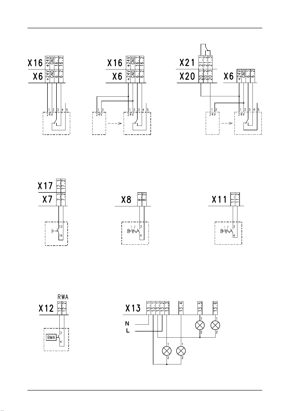
X8 Keyswitchforintermediatestop
X11 Key switch ON / OFF forautomaticclosing
X12 Smoke draining
X13 Traffic lights 2x Red / Green
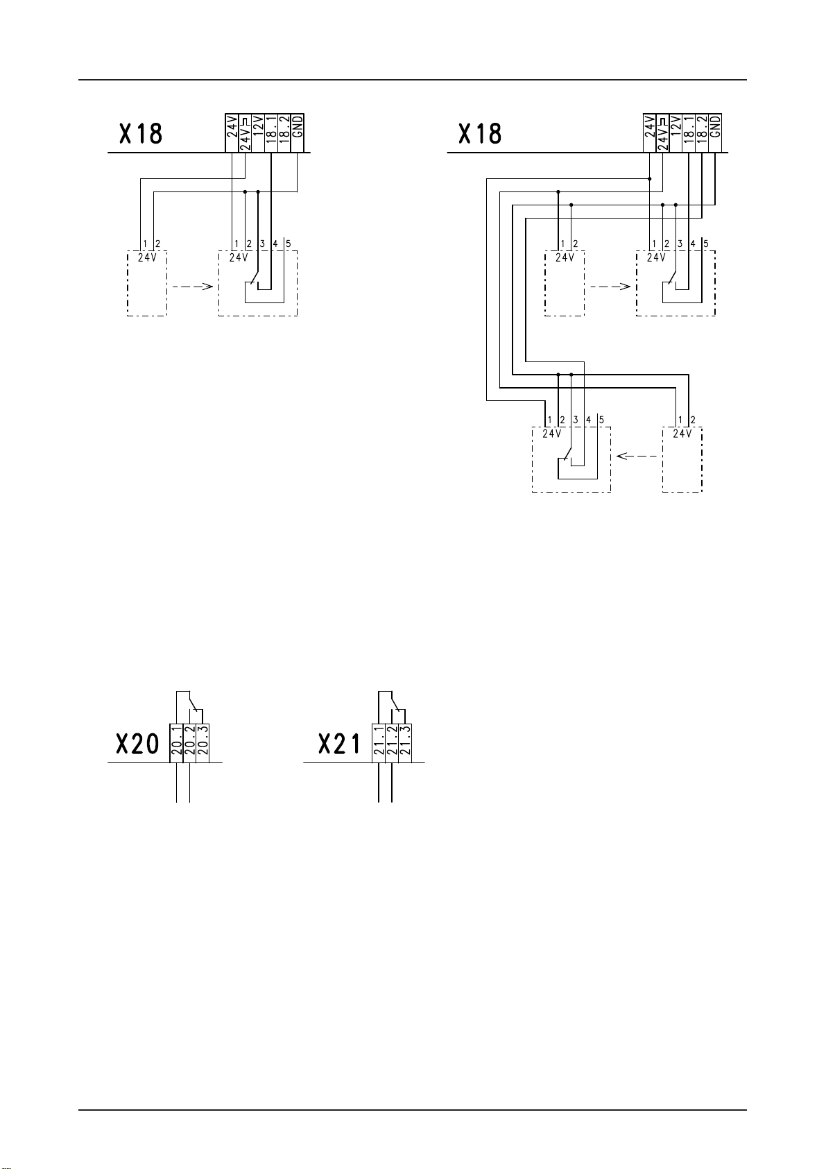
X18 Entrapment safety evaluation
X20 Potential free relay contact 1
X21 Potential free relay contact 2
X5 Three push button / Key switch
X6 Reflective photo-beam / photo-beam
X7 Ceiling pull switch / Radio control
X15 Three push button / Key switch
X16 Reflective photo-beam / photo-beam
X17 Ceiling pull switch / Radio control
Command from inside Commandfromoutside
DES Limit connection
MOT Motor connection
MMC/SD Slot for memory cards
SLF Slot for Air-lock control function
SMF Slot for Status / Information function
S1 Selector switch
V1 7-segment display
Internal push button
HARDWARE OVERVIEW
Page 14
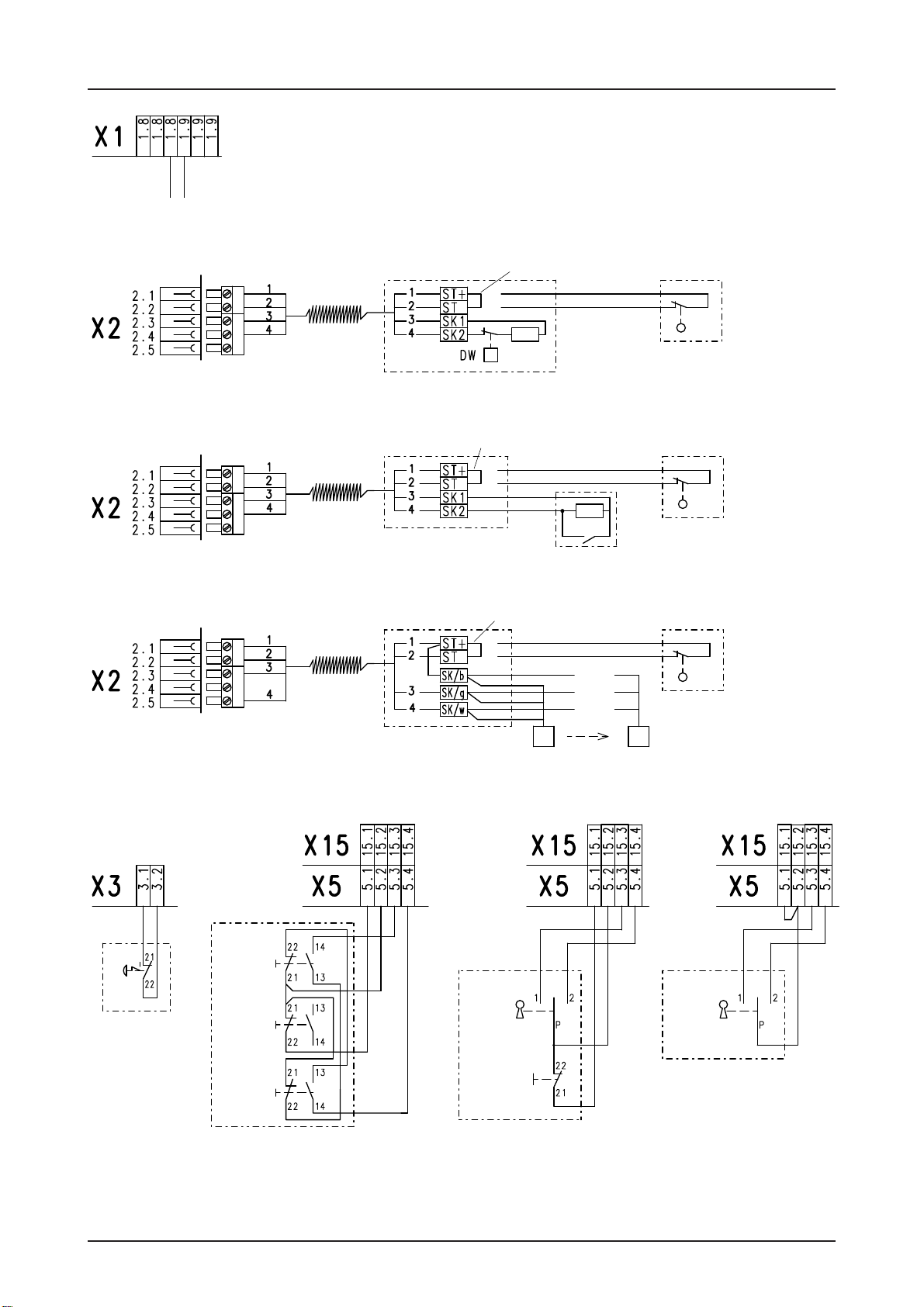
WIRING DIAGRAM
Emergency
stop button
inside
Three push
button station
inside or outside
Key switch with
stop button
inside or outside
CLOSE
STOP
OPEN
STOP
OPEN/
CLOSE
end-of-line
resistor 1K2
end-of-line
resistor 8K2
Bridge
spiral
cable
spiral
cable
Transmitter Receiver
spiral
cable
Normallyclosed contact 1K2
Normallyopen contact 8K2
Optical safety edge system
Key switch
inside or outside
or
plug-in bridge
plug-in bridge
plug-in bridge
N L1
or
br
gr
wh
Terminal box
Bridge
Terminal box
Bridge
Terminal box
L1 fused
via F1 = 1,6At
OPEN/
CLOSE
outside
inside
pass or /
slackwire
switchcontact
orcrash
detector
pass or /
slackwire
switchcontact
orcrash
detector
pass or /
slackwire
switchcontact
orcrash
detector
Page 15
WIRING DIAGRAM
Reflective photo-beam
inside or outside
Ceiling pull switch /
Radiocontrol
inside or outside
Transmitter- Receiver
photo-beam
inside or outside
Red - Green
light
inside
or
Key switch ON / OFF
automaticclosing
Key switch ON / OFF
Intermediatestop
Red - Green
light
outside
Smoke draining
contact RWA
external
or
X1 1.8/1.9
outside
inside
forclosingdirection
Transmitter-Receiver
lightcurtain
inside

Page 16
WIRING DIAGRAM
Raytectorphoto-beamor
Opticalsafetyedge
againstentrapment
single Raytectorphoto-beamor
Opticalsafetyedge
againstentrapment
double(inside- outside)
Transmitter - Receiver
Input for external entrapment
safety device 1K2
single
Input for safety edge 8K2
against entrapment
single
br
gr
wh
Transmitter - Receiver
Input for safety edge 8K2
against entrapment
double
Input for external entrapment
safety device 1K2
double
or
or
or
br
wh
gr
Receiver - Transmitter
br
gr
wh
br
gr 1
wh
br
gr 2
wh
br
gr 1
wh
br
gr 2
wh
br
wh
gr 1
gr 2
Page 17
WIRING DIAGRAM
Potential free
relay contact Potential free
relay contact
photo-beam
single,
againstentrapment
comply EN 12978
Transmitter - Receiver
Receiver - Transmitter
photo-beam
double,
againstentrapment
comply EN 12978
Transmitter - Receiver
or
Page 18
CONTROL PROGRAMMING
5.Exit programming
Turn selector until display = 00 Press selector
and
1.Enter programming Mode
Press selector switch for 3 sec. until display = 00
2.Chose program and confirm
Turn selector Press selector
3.Adjustment
Turn selector Press foil buttons
4.Memorise
Press selector Press stop-button
and
Functionen Door position
or
Functionen Door position
or
further adjustments

Page 19
Operating mode
Door position
CONTROL PROGRAMMING
4. Memorise3.Adjustment
2. Choose program and
confirm
Press
selector
Dead man OPEN
Dead man CLOSE
Door function
Self-hold OPEN
Dead man CLOSE
Self-hold OPEN
Self-hold CLOSE
Self-hold OPEN, CLOSE
(X5/X15) release for external
pushbutton function only dead man
close
Press stop
Button
Move door
upwards or downwards
Final limit open
coarse adjustment
Press
selector
Move to intermediate stopIntermediate stop
Move to switching position relay 1
Switching position Relay 1
Press stop
Button
Press stop
Button
Pre-limit safety edge can
change using +/-
Pre-limit safety edge
fine adjustment
Press
selector
Press
selector
Press stop
Button
Move door
upwards or downwards
Final limit close
coarse adjustment
Final limit open can change
without door movement using +/-
Final limit open
fine adjustment
Final limit close can change
without door movement using +/-
Final limit close
fine adjustment
Move to switching position relay 2
Switching position Relay 2Press stop
Button
Page 20
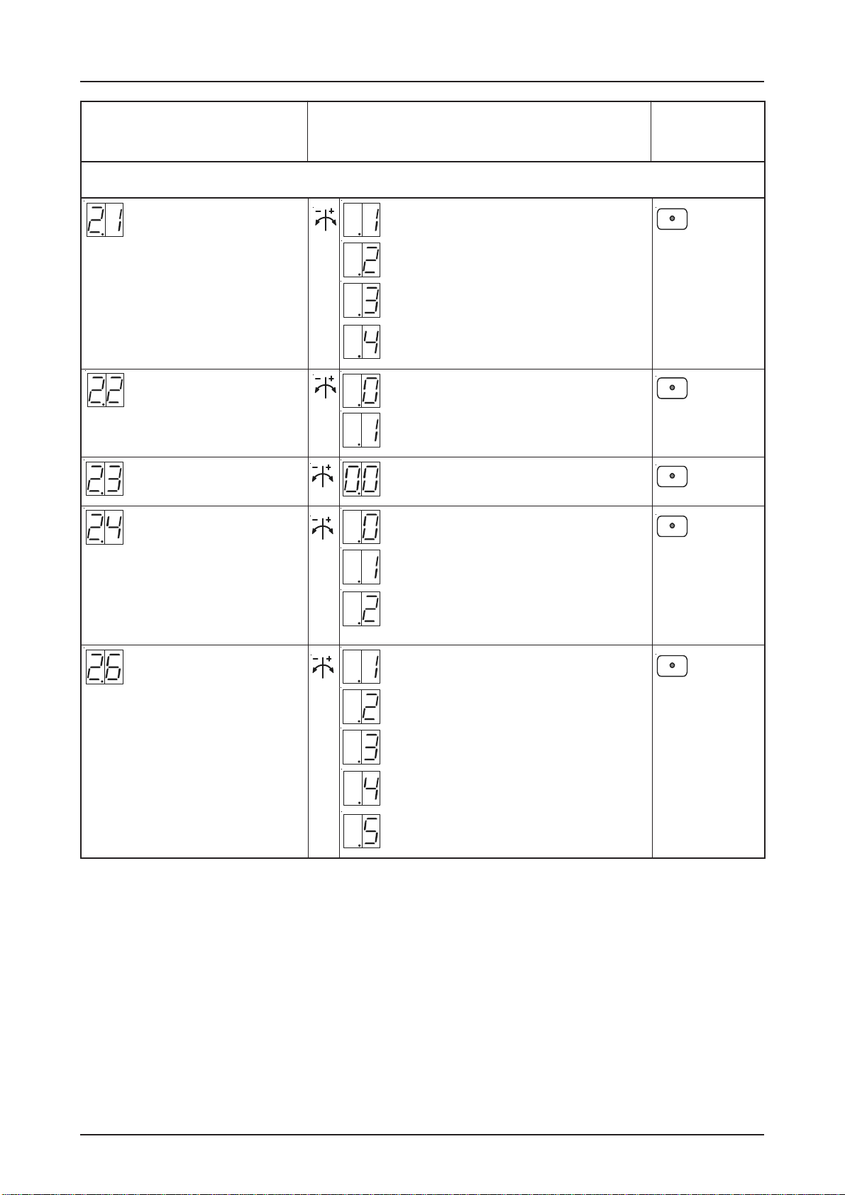
Functions
CONTROL PROGRAMMING
4.Memorise3.Adjustment
2. Choose program and
confirm
Press
selector
time can be set between 1 - 240 sec.
0 = OFF
Automatic closing
feature
Press
selector
OFF
Automatic closing after
photo-beam is interrupted
and re-made ON
Press
selector
Step by Step function
(X7 / X17): only Ceiling
pull switch / Radio
remote control
X7 / X17 = Command 1
X7 = Command 1, X17 = Command 2
X7 = Command 2, X17 = Command 1
X7 / X17 = Command 2
X7 / X17 = Command 3
Vehicle recognition, closes when the
contact is more than 1,5 sec.
triggered
Press
selector
Safety edge is activated
Safety edge function in
Pre - limit area
Safety edge is deactivated
Safety edge is activated
+ automatic ground adjustment
Press
selector
OFF
Overrun correction
ON
Active safety edge
+ re-open
Table of contents
Other Elektromaten Control Panel manuals


