Elektromaten TS 961 User manual

Electrical operating instructions
Door control panel TS 961
Software 2.6 (Design and functions subject to change)
51171292 -f 02.2013
en

Page 2
OPERATING INSTRUCTIONS
SAFETY DIRECTIONS .................................................................................................4
INSTALLATION ADVICE ..............................................................................................6
INSTALLATION OVERVIEW ........................................................................................7
ENCLOSURE INSTALLATION ....................................................................................8
CONNECTING THE CONTROL AND THE ELEKTROMATEN®..........................................................8
LIMIT SWITCH CONNECTION
Plug - in system ...........................................................................................................9
Terminalversion(untilyear 1997).................................................................................10
Single-limit-switches....................................................................................................10
MAINS SUPPLY............................................................................................................11
MOTOR CONNECTION (internal wiring) ....................................................................12
PHASE ROTATION.......................................................................................................12
LIMIT SWITCH - ADJUSTMENT ..................................................................................13
HARDWARE OVERVIEW.............................................................................................14
WIRING DIAGRAM .......................................................................................................15
CONTROL PROGRAMMING........................................................................................16
Operating mode ...........................................................................................................17
Functions .....................................................................................................................17
Reset ...........................................................................................................................18
Maintenancecyclecounter ...........................................................................................18
MEMORY CHECK ........................................................................................................18
SAFETY DEVICES .......................................................................................................19
Safety nection forshutter pass - door or slack wire switch contactX2..........................19
Mounting thespiral cable .............................................................................................19
Adjustmentpre-limit S5................................................................................................19
Typ1: Resistanceevaluation1K2with normallyclosed safety edgecontact ................20
Typ2: Resistanceevaluation 8K2 withnormally opensafety edge contact...................20
Typ 3: Optical safety edge (Vitector) ............................................................................20
Function of the safetyedge system ..............................................................................21
Emergency stop X3 ....................................................................................................21
Page

Page 3
FUNCTION DESCRIPTION..........................................................................................22
Key switch (latching) interrupt automaticclosing X4 ....................................................22
Internalpushbutton / Threepushbutton/ Keyswitch X5 ..............................................22
Runtime monitoring......................................................................................................22
Automatic closing ........................................................................................................22
Automatic closinginterruption ......................................................................................22
Photo-beam for Closing Direction X6 .........................................................................23
Ceiling pull switch / Radio control X7 ..........................................................................24
Key switch – intermediate stop X8..............................................................................24
Potential free changeovercontact X9..........................................................................25
Maintenancecyclecounter...........................................................................................25
Short circuit / overloadmonitor ....................................................................................25
OPERATING STATUS DISPLAY ..................................................................................26
TECHNICAL DATA.......................................................................................................29
LIFETIME / DOORCYKLES..........................................................................................30
DECLARATION OF INCORPORATION .......................................................................31
FUNCTION OVERVIEW ...............................................................................................32
Page

Page 4
SAFETY DIRECTIONS
Safety Regulations
During the installation, initial operation, maintenance and testing of the ELEKTROMATEN®,
itis necessary toobserve the safetyand accident-prevention regulationsvalid for thespecific
application.
In particular, you should observe the following regulations (this list is not exhaustive):
European normativ
- EN 12453
Saftey in use of power operated doors - Requirements
- EN 12445
Saftey in use of power operated doors - Test methods
Please check normative´s bellow.
VDE-regulations
- EN 418
Safety machinery
Emergency stop equipment functional aspects
Principles for design
- EN 60204-1 / VDE 0113-1
Safety of machinery - Electrical equipment of machines - Part 1:
General requirements
- EN 60335-1 / VDE 0700-1
Safety of household and similar electrical appliances - Part 1:
General requirements
Basic Directions
This control has been built in accordance with EN 12453 Industrial, commercial and garage
doors and gates - Safety in use of power operated doors - Requirements; and left the
factory in perfect condition from the point of view of safety. To maintain this condition and to
ensure safe operation, the user must observe all the directions and warnings contained in these
operating instructions.
In principle, only trained electrical craftsmen should work on electrical equipment. They must
assess the work which has been assigned to them, identify potential danger sources and take
suitable safety precautions.
Reconstruction of or changes to ELEKTROMATEN®are only permissible with the approval of
the manufacturer. Original replacement parts and accessories authorised by the manufacturer
guarantee safety. Liability ceases to apply if other parts are used.
The operational safety of an ELEKTROMATEN®is only guaranteed if it is used in accordance
with the regulations. The limiting values stated in the technical data should not be exceeded
under any circumstances (see corresponding sections of the operating instructions).
Regulations
- Please ensure that the local regulations relating to the Safety of Opera-
tions of Doors are followed

Page 5
SAFETY DIRECTIONS
Explanation of warnings
These operating instructions contain directions which are important for using the ELEKTRO-
MATEN®appropriately and safely.
The individual directions have the following meaning:
DANGER
This indicates danger to the life and health of the user if the appropriate
precautions are not taken.
Please observe the safety and accident prevention regulations valid for
the specific application. The installation of the ELEKTROMATEN®, the
opening of covers or lids and electrical connection must be carried out
when the supply is switched off.
The ELEKTROMAT®must be installed with the authorised coverings and
protective devices. Care should be taken that any seals are fitted correctly
and screw couplings are tightened correctly.
In the case of ELEKTROMATEN®with a permanent mains connection, an
all-pole main switch with appropriate back-up fuse must be provided.
Check live cables and conductors regularly for insulation faults or
breakages. When a fault is detected in the cabling, the defective cabling
should be replaced after immediately switching off the mains supply.
Before starting operation, check whether the permissible mains voltage
range of the devices corresponds to the local mains voltage.
With three – phase motor connection it must have right phase rotation
The following warnings are to be understood as a general guideline for working with the
ELEKTROMATEN®in conjunction with other devices. These directions must be observed
strictly during installation and operation.
General warnings and safety precautions
CAUTION
This warns that the ELEKTROMATEN®or other materials may be damaged if
the appropriate precautions are not taken.
Check that all screw connections are secure before operating the control
and adjusting the limit switches.

Page 6
INSTALLATION ADVICE
After the ELEKTROMATEN®is fitted we recommend the following procedure to rapidly reach
a fully functioning door.
• Installation Enclosure installation page 8
• Installation Wiring the Drive to the Control page 8
LIMIT SWITCH CONNECTION
Plug - in system page 9
LIMIT SWITCH CONNECTION
Terminal version (until year 1997) page 9
LIMIT SWITCH CONNECTION
Single-limit-switches page 10
• Check Mains supply page 11
• Check Phase rotation page 12
• Adjustmemt Limit switch - adjustment page 13
The door is ready to work in Dead man mode.
• Installation Safety devices page 15, 19, 20
• Programming Door functions page 16
The door is ready to work in automatic mode.
Check connection of external devices e.g. push button etc.
Overview to connect external devices see diagram (page 15).
After the devices are connected the programming of the control panel must be finalised.
(page 16).

Page 7
INSTALLATION OVERVIEW
Mains supply
Photo-beam
Pull switch
Three push button
Key switch (latching) interrupt
automatic closing
Emergency stop
Key switch (latching) inter-
mediate stop
Signal lamp
Connection cable ELEKTROMAT®for
Motor and mechanical limits NES 11
5
5
3
5
3
3
3
3
Spiral cable for
Safety edge system 4
( ) Number of cores in the cable
Important!
Using the connection cable out side the building is not permitted.

Page 8
ENCLOSURE INSTALLATION
Beforemounting the enclosure,the surface hasto becheckedfor flatness,slope and freedom
from vibrations. Mounting must be vertical. It is important that the door can be clearly seen
from the position of the control through-out its travel.
CONNECTING THE CONTROL AND THE ELEKTROMATEN®
After the drive and control are fitted they can be connected with a plug-in cable. The cable
has plugs on each end and for easy fitting. The plugs for motor and control panel are different
and cannot be interchanged.
Cable Description
Motor plug to control Panel
PIN -Wire-No.
1 - 3 Phase W
2 - 2 Phase V
3 - 1 Phase U
4 - 4 Neutral (N)
5 - PE Earth
Limit switch plug to control panel
PIN -Wire-No.
1 - 5 supply + 24V
2 - 6 S 5 aux. limit only for Testing of safety edge system
3 - 7 open - limit
4 - 8 S 6 aux. limit for intermediate Stop or switching contact
5 - 9 close limit
6 - 10 safety circuit common limit
Connection cable
Control panel TS 961 ELEKTROMAT®
1
2
PE
3
4
8
7
10
9
6
5
16
15
14
10
6
5
4
9
17
8
7
13
12
11
3
2
1
4
PE
- 1
- 2
- 3
- 4
- 5
PIN
- 14 -
5 -
6 -
- 2
- 3
PIN
Motor plugLimit switch plug

Page 9
LIMIT SWITCH CONNECTION
Plug - in system

Page 10
LIMIT SWITCH CONNECTION
Terminal version (until year 1997)
LIMIT SWITCH CONNECTION
Single-limit-switches
M
3
M
3

Page 11
The CONTROL PANEL TS 961 has a universal electric supply and works with the following
supplies. (See diagram Fig.1-5)
DANGER! To the life and health thru electric shock.
Before mounting the mains supply must be switched OFF.
The supply disconnect device (Main switch or CEE plug) must be installed between 0,6m
and 1,7m above floor level.
Mains supply terminal
Fig.: 1
Fig.: 2
Fig.: 3
Fig.: 5
Fig.: 4
asymmetric winding
symmetric winding
Important note!
The bridge must be fitted into the right terminal otherwise the print could be
destroyed.
400V – mains supply = 1.5 / 1.6
230V – mains supply = 1.6 / 1.7
MAINS SUPPLY
External fuse!
Control must be saved against short circuit and overload by an external fuse,
max.10Adelayed, in themains supply.Anautomatic cutoffswitchis required,
regarding the supply for three-phase or single-phase.
Whenconnectingcontroltomainssupplyamainsisolatorswitchor(16ACEE–plug)according
EN 12453 is required.
Page 12
Important Notice!
After the Mains supply has been connected by inserting the CEE plug in the
appropriatesocketor turning onthemain switch, confirmthatthe phase rotation
is correct by checking that the door opens when the OPEN push button is
operated.
If the door closes when operating the OPEN push button reverse two phases
at the terminal X1.
PHASE ROTATION
DANGER! To the life and health through electric shock.
Before changing phase rotation the mains supply must be switched OFF.
Three-phase 3 x400 V AC, N, PE
Star connection Three-phase 3 x230 V AC, PE
Delta connection
Single-phase 1x230 V AC, N, PE
symmetrical winding Single-phase 1x230 V AC, N, PE
asymmetrical winding
Important note!
For3x400VAC PEno
neutral, the brake
rectifier must be
connected between
terminal V and star-
point terminal.
brown
brown
supply for
brake
rectifier
blue supply for
brake
rectifier
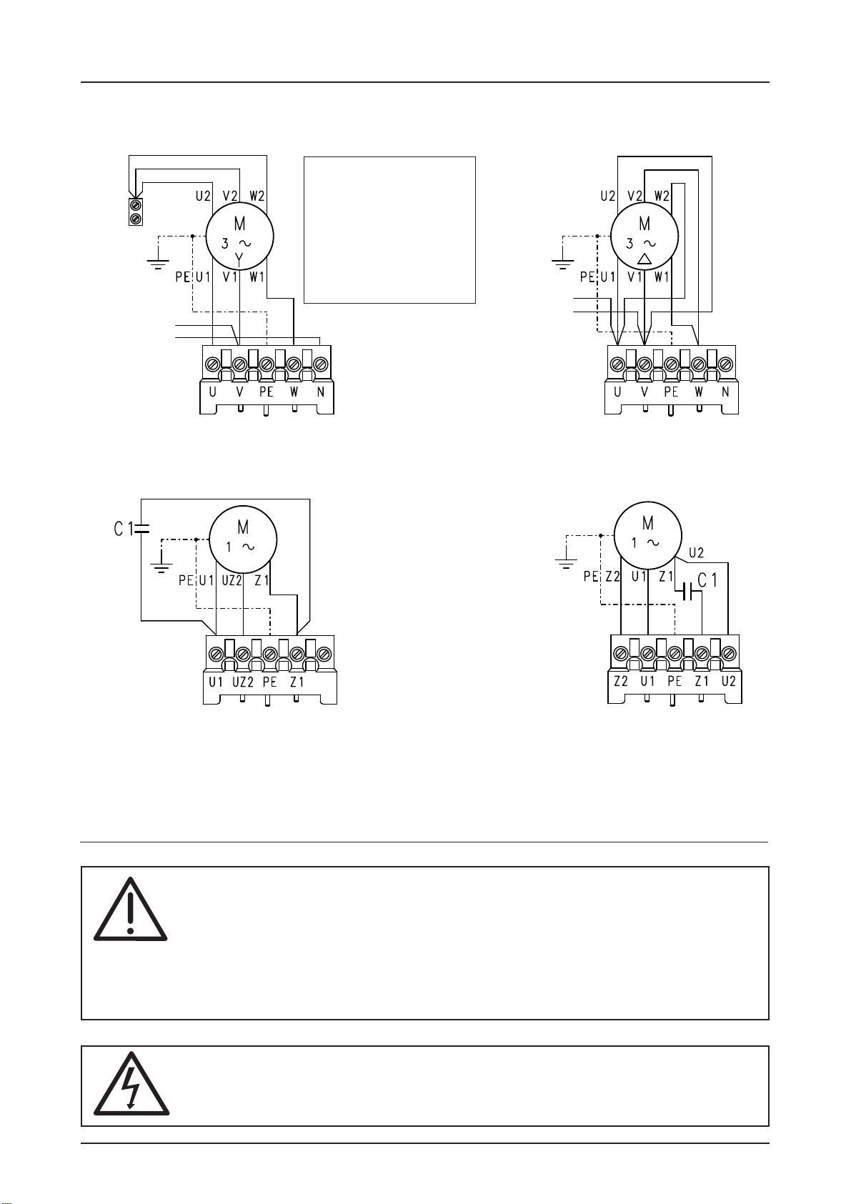
MOTOR CONNECTION (internal wiring)
blue
On several ELEKTROMATEN®the connection U1 und V1 on the motor-plug are
interchanged.

Page 13
LIMIT SWITCH - ADJUSTMENT
Working limit adjustment is complete
The door could be moved in DEADMAN mode UP/DOWN
Further adjustments see programming mode (Page 16)
1. Move the door to final open position
press button to reach upper limit
Door open
2. Adjustment final open limit
3. Move the door to final close position
press button to reach lower limit
Door close
4. Adjustment final close position
After checking the phase rotation, the limit switches must be adjusted in the following steps.
When open and close position limits have been set the safety limits are automatically
pre-adjusted. Eventually fine adjustment could be required. Please see Mechanical
Operating Instruction.
After reaching the final open
position the limit S3 must be
switched with green limit cam S3
and panel display changes to
„Door final open position“
After reaching the final close
position the limit S4 must be
switched with green limit cam S4
panel display changes to „Door
final close position“
Display shown-
door open
Display shown-
door closed
Display flashing
during the door
upwards movement
Display
shown - door
between final
limit positions
Display flashing
during door
downwards
movement
Display shown-
door between
final limit
positions

Page 14
PEPE PE PE
3.1
3.2
4.1
4.2
5.2
5.1
5.3
5.4
6.1
GND
24V
6.2
7.1
7.2
8.1
8.2
2.5
2.4
2.3
2.2
2.1
1.8
1.9
9.1
9.2
9.3
1.1
MOT NES
1.2
1.3
1.4
F1 = 1,0A t
FT
1.5
1.6
1.7
TS 961
HARDWARE OVERVIEW
X1
X9 X3
X2
Description Print:
X1 Mains supply S1 Selector switch
external supply 230V V1 7-segment display
1.9 = L1 fused with F1 = 1A MOT Motor connection
1.8 = N NES Mechanicallimit connection
(only with 3 x 400V, N, PE und 1 x 230V, N, PE) Internal push button
X2 Safety edge system and pass-door plug
X3 Emergency push button
X4 Key switch (latching) interrupt automatic closing
X5 Three push button / key switch
X6 Light barrier reflective or receiver- transmitter type
X7 Ceiling pull switch / Radio control
X8 Key switch for intermediate stop
X9 Potential free relay contact
warning light or annunciator
X4 X5 X6 X7 X8
S1
V1

Page 15
WIRING DIAGRAM
Page 21-25 Page 19, 20
Emergency
stop button
Key switch
(latching) interrupt
automatic closing Three push button
station Key switch with stop
button
Close
Stop
Open
Stop
Open/
Close
Radio receiver
Ceiling pull switch
Transmitter- Receiver
photo-beam
Reflective photo-
beam
Key switch intermediate
stop Warning light Aux. contact
Terminal box Bridge
passor / slack wire
switch contact
passor / slack wire
switch contact
end-of-line
resistor 1K2
end-of-line
resistor 8K2
Terminal box Bridge
Terminal box Bridge
passor / slack wire
switch contact
spiral cable
spiral cable
Transmitter Receiver
brown
green
white
spiral cable
Normallyclosed contact 1K2
Normallyopen contact 8K2
Optical safty edge system
Key switch
Open/
Close
or or
or
N L1
L1 fused via
F1 = 1At
or
plug-in bridge
plug-in bridge
plug-in bridge
or

Page 16
CONTROL PROGRAMMING
5. Exit programming
Turn selector until display = 00 Press selector
and
1. Enter programming Mode
Press selector switch for 3 sec. until display = 00
2. Chose program and confirm
Turn selector press selector
3. Adjustment
Turn selector
4. Memorise
Press selector
and
Functionen
Functionen
further adjustments

Page 17
CONTROL PROGRAMMING
4. Memorise3. Adjustment
2. Choose program and
confirm
Press
selector
Dead man OPEN
Dead man CLOSE
Door function
Self-hold OPEN
Dead man CLOSE
Self-hold OPEN
Self-hold CLOSE
Press
selector
Safety edge is activated
Safety edge function
in Pre - limit area
Safety edge is deactivated
Press
selector
time can be set between 1 - 240 sec.
0 = OFF
Automatic closing
feature
Press
selector
OFF
Automatic closing
after photo-beam is
interrupted
and re-made ON
Press
selector
OFF
Relay function
Switch contact impulse signal
Switch contact continuous
Self - hold OPEN, CLOSE
(X5) release for external pushbutton
function only dead man close
Press
selector
Commands
door travels to Open or Closed position
during closing door Stops and re-opens
Step by Step function
(X7): only Ceiling pull
switch / Radio remote
control Commands
OpenStopCloseStopOpen
Operating mode
Functions
Signal lamp starts flashing with 3 sec. pre-
warning time when door Open’s and Close’s;
Continuous light while the door is moving
Signal lamp starts flashing with 3 sec. pre-
warning time only when door Close’s
direction; Continuous light while the door
is moving
Runtime monitoring
Steady burning light with 3 sec. warning
flashes before the door starts for Opening
or Closing
Press
selector
time can be set between 1 - 90 sec.
0 = OFF
Signal lamp: Continuous red light with 3
sec. pre-warning from open position

Page 18
MEMORY CHECK
Press
selector
Info Cycle counter
7- digit
Last 2 faults would be alternately displayed.
Program version will be displayed
Displayed
Info last 2 faults Press
selector
Info Program changes
7- digit
Info Program version
M HT ZT T H Z E
Press
selector
Press
selector
M HT ZT T H Z E
The cycles would be displayed as follow.
M = 1.000.000 H = 100
HT = 100.000 Z = 10
ZT = 10.000 E = 1
T = 1.000
The Number of program changes would be dis-
played as follow.
M = 1.000.000 H = 100
HT = 100.000 Z = 10
ZT = 10.000 E = 1
T = 1.000
2. Chose program and
confirm
01-99 correspond from 1.000 up to
99.000 Count down cycles
Counter adjustment
Display appears „CS“ and adjusted
number of cycles
Changing to DEADMAN display appears
„CS“ and adjusted number of cycles
Changing to DEADMAN same as 0.2 reset
to about 500 cycles possible, press 3 sec.
Stop – Button
Reaction when
reaching 0
Reset
Maintenance cycle counter
RESET except cycle-
and Program change
counter
Reset Press stop
button
3 sec.
4. Set
3. Adjustment
2. Chose program and
confirm
Press
selector
Press
selector
CONTROL PROGRAMMING

Page 19
SAFETY DEVICES
Safety edge system with optional connection for shutter pass - door or slack
wire switch contact X2
The control recognizes and works with 3 different safety edges.
Each one needs a special 4 core spiral cable and includes an optional shutter pass - door or
slack wire switch contact.
The spiral cable connection must be made on the print with the plug provided. The opposite
side of the cable is connected to a terminal box or a signal (pressure switch) emitter.
Important note!
When connecting a safety edge, take account of EN 12978 for
Industrial, commercial and garage doors and gates - Safety devices for
power operated doors - Requirements and Test methods.
Typ 1: Resistance evaluation 1K2 with normally closed safety edge contact
(safety edge with pressure wave switch and "Testing")
Typ 2: Resistance evaluation 8K2 with normally open safety edge contact
Typ 3: Optical safety edge (Vitector)
Mounting the spiral cable
A bush is provided on both sides of the control box for mounting the spiral cable.
Push the plugs through into the enclosure until there is sufficient cable to allow the (2 and 3
pole) plugs to be connected to the board. The plug with two cores must be connected to the
passdoor or slack wire switch terminals.The three core plug must be connected to the safety
edge terminal.
The control panel TS 961 recognizes on first installation the safety edge system being used.
If passdoor / slack wire switch contact exists, remove bridge at terminal ST and ST+ in
the terminal box. The plug at terminal X2 must be removed.
Adjustment pre-limit S5
The pre-limit switch S5 must be set to avoid a continuously re-opening of the door out of the
final close position, if the safety edge system has been actuated.
Set the S5 limit switch 5 cm before the final close position to interrupt the re-open function.

Page 20
The principle of operation is as a one way light barrier. By activating the safety edge, the
photo-beam will be interrupted.
Typ 3: Optical safety edge (Vitector)
Typ 2: Resistance evaluation 8K2 with normally open safety edge contact
This evaluation system is made for electrical safety edges within an end-of-line resistor of
8K2-+5%0,25W.Theresistormustbeconnectedparallelwiththeswitchinthesafetyedge.
This evaluation system is made for pressure-wave switches (N/C) within an end-of-line
resistor of 1K2 +/- 5% 0,25W.
A pressure wave is generated by compressing the rubber profile, which is conducted to the
pressure-wave switch through the plastic hose.The system should be tested in the CLOSE
position. The pre-limit would be set automatically and activate the "Testing function".
When the shutter runs over the pre-limit door position, a timer of two seconds starts to
countdown at once. If a pressure wave activates the pressure switch in this time the TS
970recognizes the functionof the safety edge. Ifthe pressure switch has notbeen activated,
the control goes into fault mode and the system works only in DEAD MAN function in
downwards direction. Fault information F 2.8 would be displayed.
Typ 1: Resistance evaluation 1K2 with normally closed safety edge contact
Pressure-wave switch - function
The contact between the contact screw and
diaphragm is opened (opening contact). The
pressure-wave switch is set to a release pres-
sure of approx. 1,5 mbar.
The valve screws are set to a throughput of
110 ml/min with a static admission pressure
of 5 mbar. This warrants that a maximum tem-
perature increase of 30° is compensated for in
20 minutes.
The setting of the valve screws may not be
altered. Should the release pressure be insuf-
ficient (pressure wave too insensitive), the
contact screw may be turned counterclock-
wise to the left by 1-2 graduation marks. The
switch's sensitivity is thus increased.
In case of excessive sensitivity, the contact
screw is set clockwise by 1-2 graduation
marks (decreased sensitivity).
Pressure-wave switch
valve screws (may
not be altered)
Hose contact for:
pressure opens
contact screw
SAFETY DEVICES
Table of contents
Other Elektromaten Control Panel manuals


Popular Control Panel manuals by other brands


Mitsubishi Electric
Mitsubishi Electric PANEL_RS2 installation manual

AKO
AKO PROPlus manual

Teletek electronics
Teletek electronics iRIS4 installation manual

Pulsar
Pulsar 17/TRP50/SATEL Assembly instruction

Eight
Eight TouchOne G3 Installation and user manual

Nittan
Nittan CPC-4A-24 Operating instructions manual