Elektromaten TS 980 User manual

Electrical operating instructions
Door control panel TS 980
(Design and functions subject to change)
51171150 -b 07.2007
en

page 2
OPERATING AND INSTALLATION INSTRUCTIONS
PAGE
SAFETY DIRECTIONS .................................................................................................4
ENCLOSURE INSTALLATION....................................................................................6
MAINS SUPPLY ...........................................................................................................7
SAFETY DEVICES .......................................................................................................8
Safety edge system with optional connection for shutter pass-door or slack-wire switch. .8
SAFETY DEVICES .......................................................................................................9
Resistance evaluation 8K2 with normally open safety edge contact ................................9
Resistance evaluation 1K2 with normally open safety edge contact ................................9
Resistance evaluation 1K2 with normally closed safety edge contact ..............................10
Resistance evaluation 8K2 with normally closed safety edge contact ..............................11
Optical safety edge (Fraba Type) ................................................................................... 11
Safety against entrapment .............................................................................................. 12
Slack-wire Switch ...........................................................................................................12
Emergency Stop ............................................................................................................12
Photo-beam ...................................................................................................................13
PUSH BUTTON ............................................................................................................14
Three push button station ............................................................................................... 14
Intermediate stop mode .................................................................................................15
Ceiling pull switch ...........................................................................................................15
RELAY CONTACT ........................................................................................................16
PCB PRINT OVERVIEW ..............................................................................................17
INITIALISATION ............................................................................................................18
Initial installation .............................................................................................................18
Language selection ........................................................................................................19

page 3
PAGE
ADJUSTMENT OF THE LIMITS/ BASIC-FUNCTION ..................................................20
Adjust the mechanical limits NES ...................................................................................20
When control has recognised DES digital limits, adjust limit DES ...................................22
Fine adjustment ..............................................................................................................23
Safety devices ............................................................................................................... 24
Intermediate stop ...........................................................................................................26
Selecting Aux. Function mode ........................................................................................27
Adjusting the automatic close feature .............................................................................27
ADJUSTMENT: AUXILIARY FUNCTIONS ..................................................................27
Adjustment relay contact 1, pre-information mechanical limit NES operation ..................28
Adjustment relay contact 2 .............................................................................................30
Adjustment of pre-limit ....................................................................................................31
Adjustment: Auxiliary Functions ..................................................................................... 32
Automatic ground adjustment .........................................................................................32
Overrun correction should be selected only for rapid doors. ............................................33
Final program ................................................................................................................33
REQUEST INFO MODE ...............................................................................................34
INSTALLATION PLAN .................................................................................................. 35
CONFIGURATION PLAN FOR LIMIT SWITCHES .......................................................36
FAULT REPORT .......................................................................................................... 37
TECHNICAL DATA .......................................................................................................38

page 4
SAFETY DIRECTIONS
Safety Regulations
During the installation, initial operation, maintenance and testing of the ELEKTROMATEN, it is
necessary to observe the safety and accident-prevention regulations valid for the specific
application.
In particular, you should observe the following regulations (this list is not exhaustive):
European normativ
- DIN EN 12453
Saftey in use of power operated doors - Requirements
- DIN EN 12445
Saftey in use of power operated doors - Test methods
- DIN EN 12978 Industrial, commercial and garage doors and gates -
Safety devices for power operated doors - Requirements and Test methods
Please check normative´s bellow.
VDE-regulations
- DIN EN 418
Safety machinery
Emergency stop equipment functional aspects
Principles for design
- DIN EN 60204-1 / VDE 0113-1
Safety of machinery - Electrical equipment of machines - Part 1:
Prescriptions générales
- DIN EN 60335-1 / VDE 0700-1
Safety of household and similar electrical appliances - Part 1:
General requirements
Basic Directions
This control has been built in accordance with DIN EN 12453 Industrial, commercial and garage
doors and gates - Safety in use of power operated doors - Requirements; DIN EN 12978
Industrial, commercial and garage doors and gates - Safety devices for power operated
doors - Requirements and Test methods - and left the factory in perfect condition from the point
of view of safety. To maintain this condition and to ensure safe operation, the user must observe all
the directions and warnings contained in these operating instructions.
In principle, only trained electrical craftsmen should work on electrical equipment. They must assess
the work which has been assigned to them, identify potential danger sources and take suitable
safety precautions.
Reconstruction of or changes of this control Panel TS 980 is only permissible with the approval of the
manufacturer. Original replacement parts and accessories authorised by the manufacturer guarantee
safety. Liability ceases to apply if other parts are used.
The operational safety of this control Panel TS 980 is only guaranteed if it is used in accordance with
the regulations. The limiting values stated in the technical data should not be exceeded under any
circumstances (see corresponding sections of the operating instructions).
Regulations
- Please ensure that the local regulations relating to the Safety of Opera-
tions of Doors are followed

page 5
SAFETY DIRECTIONS
Explanation of warnings
These operating instructions contain directions which are important for using the ELEKTROMATEN
appropriately and safely.
The individual directions have the following meaning:
DANGER
This indicates danger to the life and health of the user if the appropriate precautions
are not taken.
Please observe the safety and accident prevention regulations valid for the
specific application.
The ELEKTROMATEN must be installed with the authorised coverings and
protective devices. Care should be taken that any seals are fitted correctly
and screw couplings are tightened correctly.
In the case of ELEKTROMATEN with a permanent mains connection, an all-
pole main switch with appropriate back-up fuse must be provided.
Check live cables and conductors regularly for insulation faults or breakages.
When a fault is detected in the cabling, the defective cabling should be
replaced after immediately switching off the mains supply.
Before starting operation, check whether the permissible mains voltage range
of the devices corresponds to the local mains voltage.
With three – phase motor connection it must have right phase rotation
The following warnings are to be understood as a general guideline for working with the
ELEKTROMATEN in conjunction with other devices. These directions must be observed strictly
during installation and operation.
General warnings and safety precautions
CAUTION
This warns that the ELEKTROMATEN or other materials may be damaged if the
appropriate precautions are not taken.
page 6
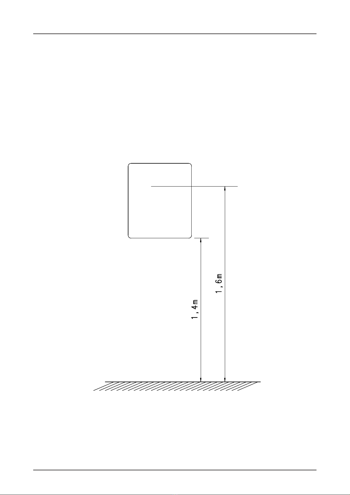
ENCLOSURE INSTALLATION
Before mounting the enclosure the surface has to be checked for flatness, slope and freedom
from vibrations. For installation we recommend to use the template supplied. Mounting must
be vertical.
Mounting, see drawing.
page 7
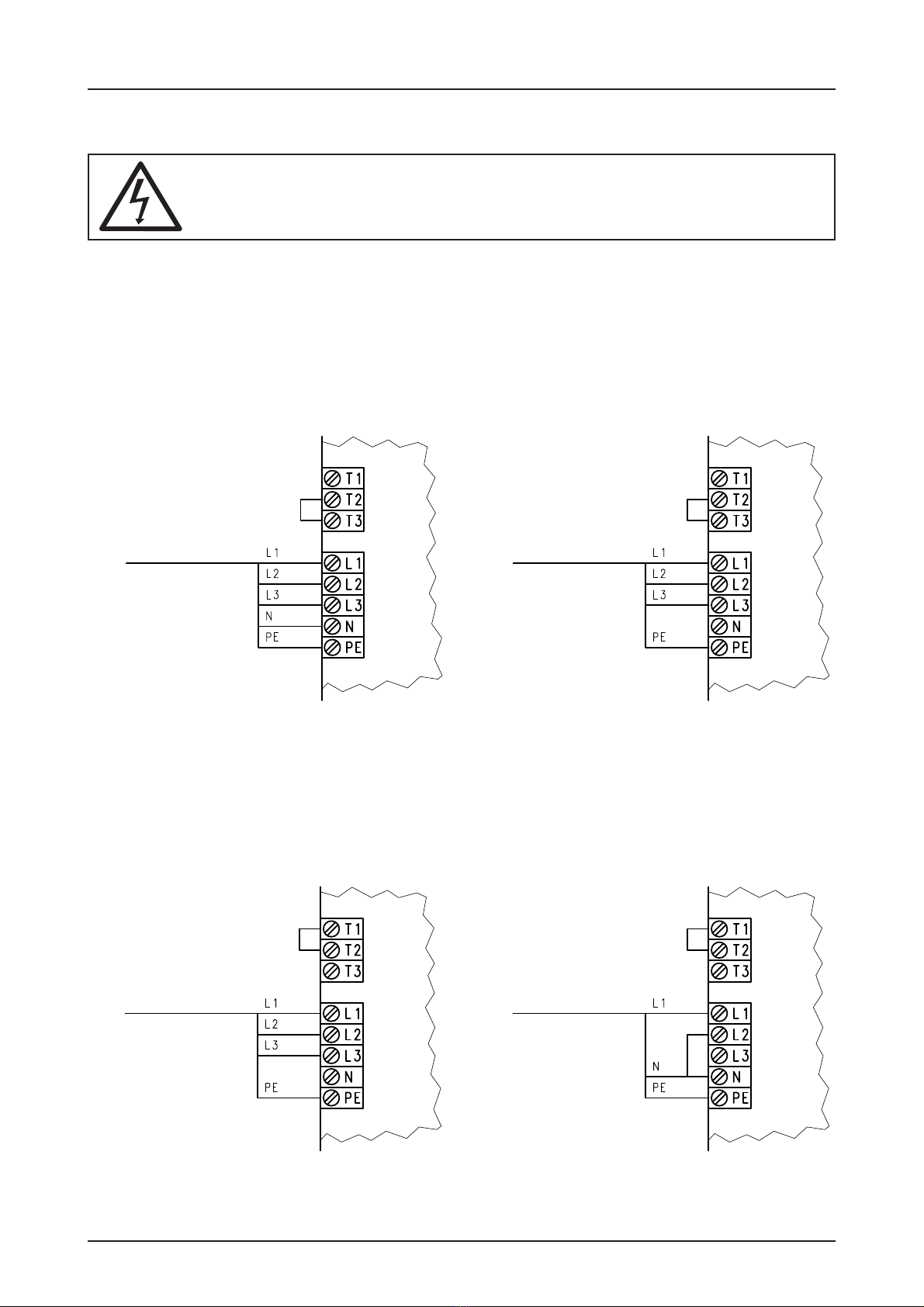
MAINS SUPPLY
Fig. 1 Mains supply 3x 400V,N,PE
Fig. 3 Mains supply 3x 230V,PE
Fig. 2 Mains supply 3x 400V,PE
Fig. 4 Mains supply 1x 230V,N,PE
3 x 400V, N, PE 3 x 400V, PE
3 x 230V, PE 1 x 230V, N, PE
Warning! This indicates danger to the life through electric shock.
Before starting assembly, disconnect the equipment from the electricity supply.
The control panel TS 980 works with the following supplies. ( See diagrams)
Fig.1 to Fig.4 mains supply
The TS 980 control can be used with all GfA ELEKTROMATEN up to 2,2KW
page 8
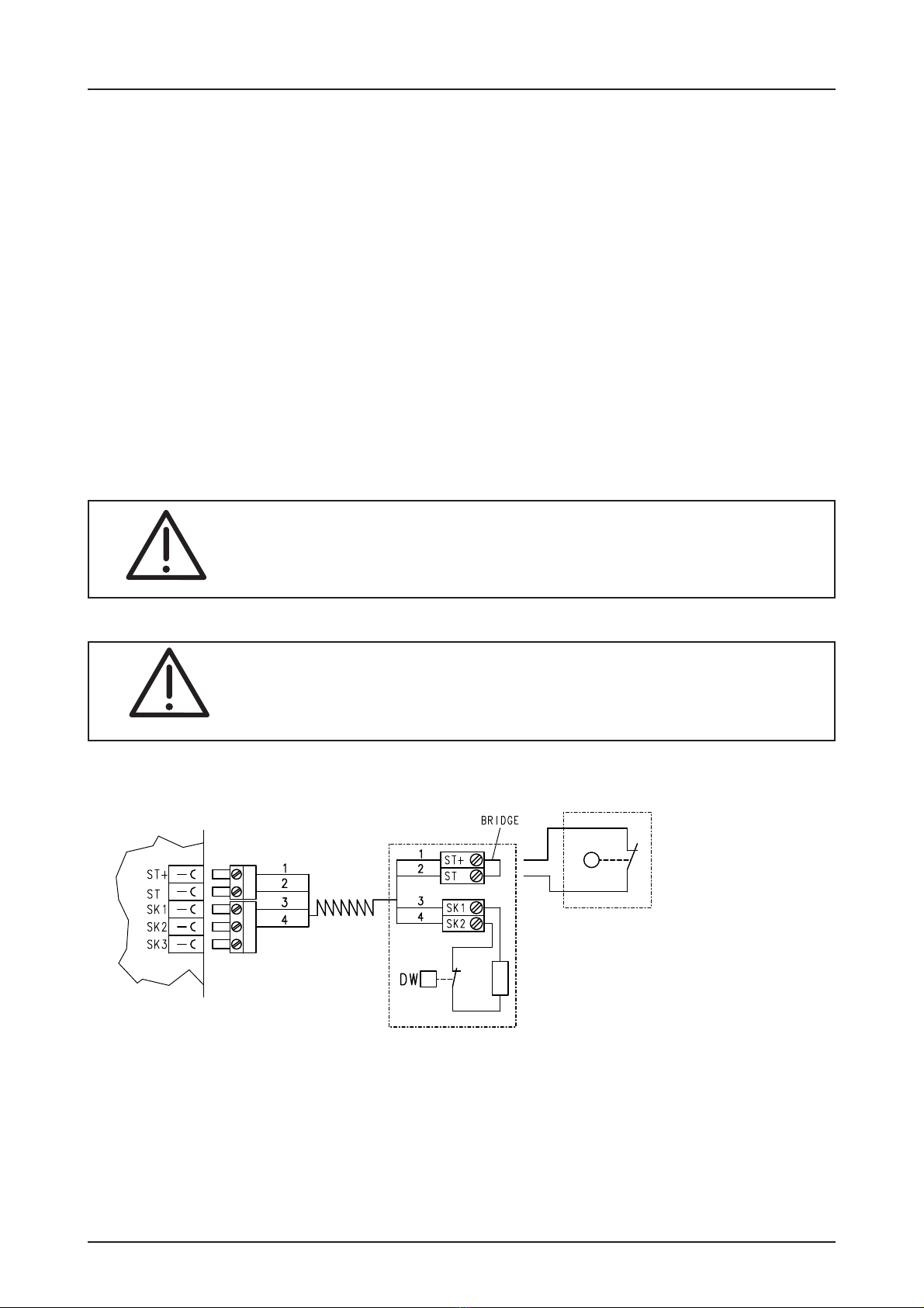
Safety edge system with optional connection for shutter pass-door or
slack-wire switch.
The control recognises and works with 5 different safety edges.
Each one needs a special 4 core spiral cable and includes an optional shutter pass-door or
slack-wire switch contact.
The spiral cable connection must be made on the print with the plug provided. The other end is
connected to a terminal box or a signal emitter, such as a pressure switch.
-Resistance evaluation 8K2 with normally open safety edge contact (page 9)
-Resistance evaluation 1K2 with normally open safety edge contact (page 9)
-Resistance evaluation 1K2 with normally closed safety edge contact (page 10)
(pressure switch with "Pressure Wave Testing")
-Resistance evaluation 8K2 with normally closed safety edge contact (page 11)
-Optical safety edge system (Fraba type) (page 11)
Important note!
When connecting a safety edge, make sure of compliance with DIN EN 12978
Industrial, commercial and garage doors and gates - Safety devices for
power operated doors - Requirements and Test methods.
Mounting the spiral cable
A bush is provided on both sides of the control box for mounting the spiral cable.
Push the blue plugs through into the enclosure until there is sufficient cable to allow them to be
connected to the board. The plug with two cores must be connected
to the pass-door and slack-wire switch terminals. The three core plug must be connected to
the safety edge terminals.
The control panel TS 980 recognises automatically the type of safety edge used.
Please check after installation all terminal screws are tight to ensure they are finger
safe.
SAFETY DEVICES
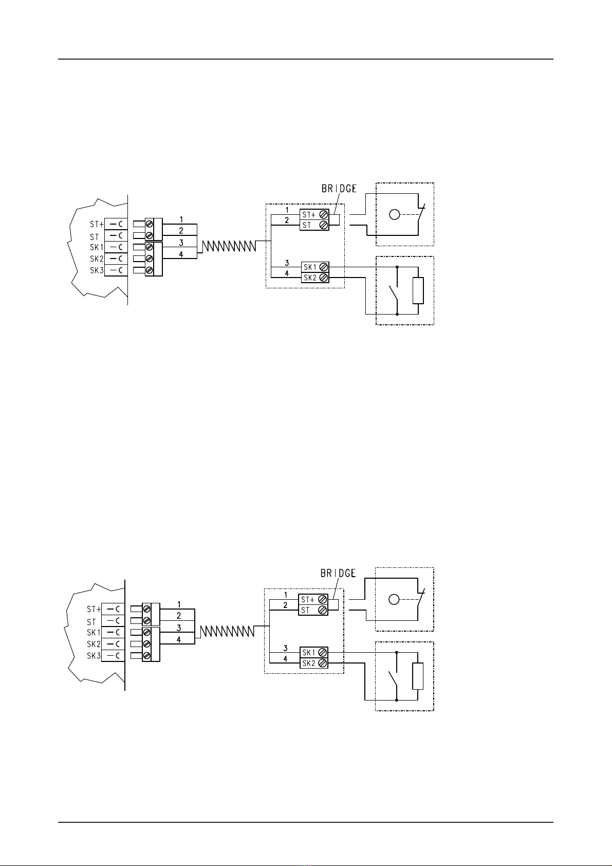
page 9
Resistance evaluation 8K2 with normally open safety edge contact
This evaluation system is made for electrical safety edges within an end-of-line resistor of 8K2.
The resistor must be connected in series with the switch in the safety edge.
If a pass-door or slack-wire switch is to be connected, remove the bridge at terminals ST and
ST+ in the terminal box
SAFETY DEVICES
fig. 1 wiring diagram electrical safety edge with 8K2 resistor and normally open contact
This evaluation system is made for electrical safety edges within an end-of-line resistor of 1K2.
The resistor must be connected in series with the switch in the safety edge.
If a pass-door or slack-wire switch is to be connected, remove the bridge at terminals ST and
ST+ in the terminal box.
Resistance evaluation 1K2 with normally open safety edge contact
fig. 2 wiring diagram electrical safety edge with 1K2 resistor and normally open contact
pass-door/slack-
wire switch contact
end-of-line
resistor 8K2
end-of-line
resistor 1K2
pass-door/slack-
wire switch contact
page 10
Resistance evaluation 1K2 with normally closed safety edge contact
This evaluation system is made for pressure-wave switches ( N/C ) with an end-of-line resistor
of 1K2.
A pressure wave is generated by compressing the rubber profile, which is conducted to the
pressure-wave switch through the plastic hose. The system should be tested as the door
closes. The limit S5 must be set to activate the "Testing function" (when using mechanical
limit switches). For adjusting the testing function, close the shutter and stop it max. 5 cm
before the closed position, now set limit S5.
When the shutter runs over the limit S 5, a timer of two seconds starts to countdown.
If a pressure wave activates the pressure switch in this time the TS 980 recognises the function
of the safety edge. If the pressure switch has not been activated, the control goes into fault
mode and the system will only work in DEAD MAN mode in the close direction.
If pass-door or slack-wire switch contact is to be connected, remove the bridge at terminal ST
and ST+ in the terminal box.
Important note!
When setting the closed position the rubber edge has to send out a
pressure wave sufficient to operate the pressure switch.
Important note!
When using a safety edge system the limit S5 must be set when using
mechanical limits.
Close the shutter and stop 5 cm before the end position, now set limit S5.
SAFETY DEVICES
Fig.3: Wiring diagram resistance evaluation 1K2 normally closed contact
(pressure - wave switch)
end-of-line
resistor 1K2
pass-door/slack-
wire switch contact

page 11
The principle of operation is similar to a through-beam light barrier with self testing. By activating
the safety edge, the light beam is interrupted. If a pass-door or slack-wire switch is to be
connected, remove the bridge at terminals ST and ST+ in the terminal box.
Optical safety edge (Fraba Type)
The fig. 5 wiring diagram optical safety edge system (Fraba type)
Resistance evaluation 8K2 with normally closed safety edge contact
This evaluation system is made for safety edges within an end-of-line resistor of 8K2. When a
normally closed safety edge system which works in quiescent current mode is connected, a
separate safety edge control has to be connected. The resistor must be connected in series
with the switch in the safety edge.
If pass- door or slack-wire switch is to be connected, remove bridge at terminals ST and ST+
in the terminal box.
SAFETY DEVICES
fig. 4 wiring diagram electrical safety edge with 8K2 resistor and normally open contact
Transmitter Receiver
pass-door/slack-
wire switch contact
end-of-line
resistor 8K2
pass-door/slack-
wire switch contact
To monitor the end of line safety edge system correctly, the resistor should be mounted
close to the switching unit. l. e. pressure switch.

page 12
Emergency Stop
In accordance DIN EN 418 the emergency Stop
button has to meet category 0.
Slack-wire Switch
For doors with a cable or chain drive, in
accordance DIN EN 12453 slackness must
be monitored. The control can be done with a
slack-wire switch which can be connected
directly on TS 980 terminals SL+/SL the
reaction is just STOP.
Fig. 2: Slack-wire switch wiring Fig. 3: EMERGENCY STOP wiring
This is an additional safety system ( e.g. self-testing light barrier) which shall prevent trapping a
person or obstacle in the door. In accordance with EN 12453 monitoring is required of each
door or shutter where lifting of people or obstacles cannot be prevented (e.g. Grilles).
A separate control system within an end-
of-line resistor of 1K2 should be
connected. TS 980 recognises various
faults - short circuit, contact or supply
interruption.
This safety system is only in effect in the
upwards direction.
When recognising a contact the door
movement upwards Stops and returns
downwards for only 2 sec.. Then the door
Stops until a new command is received.
At the same time the control-display
displays Emergency Stop Entrapment.
Important note
In accordance with EN 954 -1 the safety edge control of the
entrapment device has to meet category 2.
Safety against entrapment
SAFETY DEVICES
EMERGENCY
STOP
Slack-wire
Switch
Fig. 1: Wiring diagram of indicator with a monitoring
resistor.
monitoring
resistor
end-of-line
resistor 1K2

page 13
Photo-beam
One external photo-beam (through-beam or reflex type) can be connected.
If the beam is interrupted while the shutter is closing, it will STOP and move BACK UP. The
beam is only operational in the closing direction.
Supply for the beam is 230V AC or 24V DC. A timed return after interruption in the automatic
closing mode can be programmed only when a beam is connected (see program).
In accordance with EN 954 -1 the beam has to meet category B.
Fig. 4: Wiring diagram for reflective photo-beam
Important note!
Photo beam on the 24 V DC power supply may not exceed 60 mA.
SAFETY DEVICES
Fig. 5: Wiring diagram for thro-beam-photo-beam
1
2
3
4
(1)
(2)
1234
1
2
3
4
(1)
(2)
123412
Reflektor
Transmitter/
Receiver connection 24V
connec-
tion 230V
switching contact
Transmitter Receiver connection 24V
connec-
tion 230V
switching contact
page 14
PUSH BUTTON
Terminals are provided for two three button stations
Important Note
The first push button station has to be installed where the door movement
can be seen through-out its travel for dead-man mode control.
The Second push button can be installed at any other place and the door
movement has not to be controlled. When the control goes into fault mode
the second pushbutton will be disabled.
Three push button station
Fig. 1: Wiring diagram three button station
22
21
21
22
21
22
14
13
13
14
13
14
OPEN
STOP
CLOSE
22
21
21
22
21
22
14
13
13
14
13
14
OPEN
STOP
CLOSE
Push button 2
Push button 1

page 15
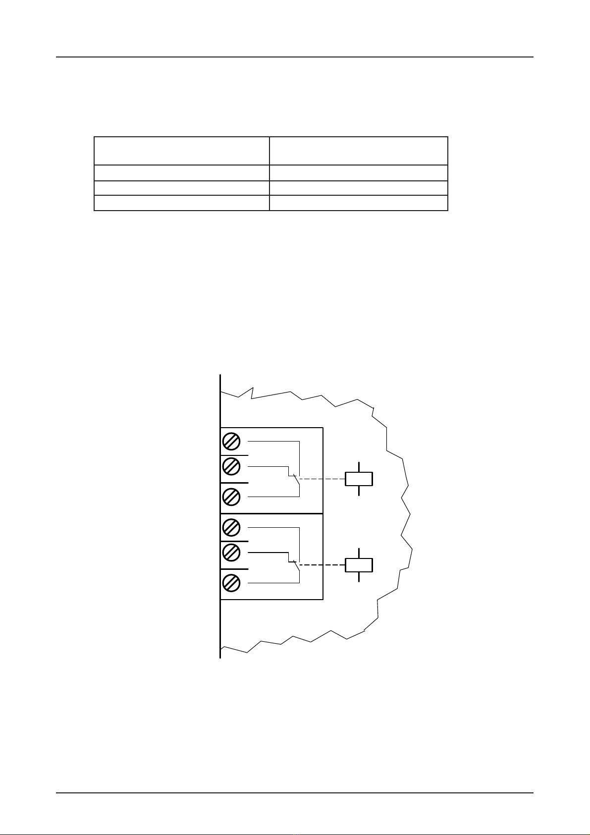
Intermediate Stop mode can be activated with a key switch (latching - ON-OFF) and setting the
limit S6 at the required intermediate position when using mechanical limits (see page 26).
The intermediate shutter position "PART-OPEN" is only in effect in the upwards direction and is
the new OPEN position. By turning the key switch to the OFF position, the shutter works in
standard mode.
With each command (impulse) the shutter responds as follows:
Shutter position Shutter mode
Shutter closed Shutter moves to open position
Shutter moving open No reaction
Shutter open Shutter moves to close position
Shutter intermediate position open Shutter moves to close position
Shutter moving closed Shutter will STOP and move BACK UP
Intermediate stop mode
Ceiling pull switch
PUSH BUTTON
Fig. 1 wiring key switch (latching)
Fig. 2: wiring ceiling pull switch
12
Key - switch
ceiling pull switch
page 16
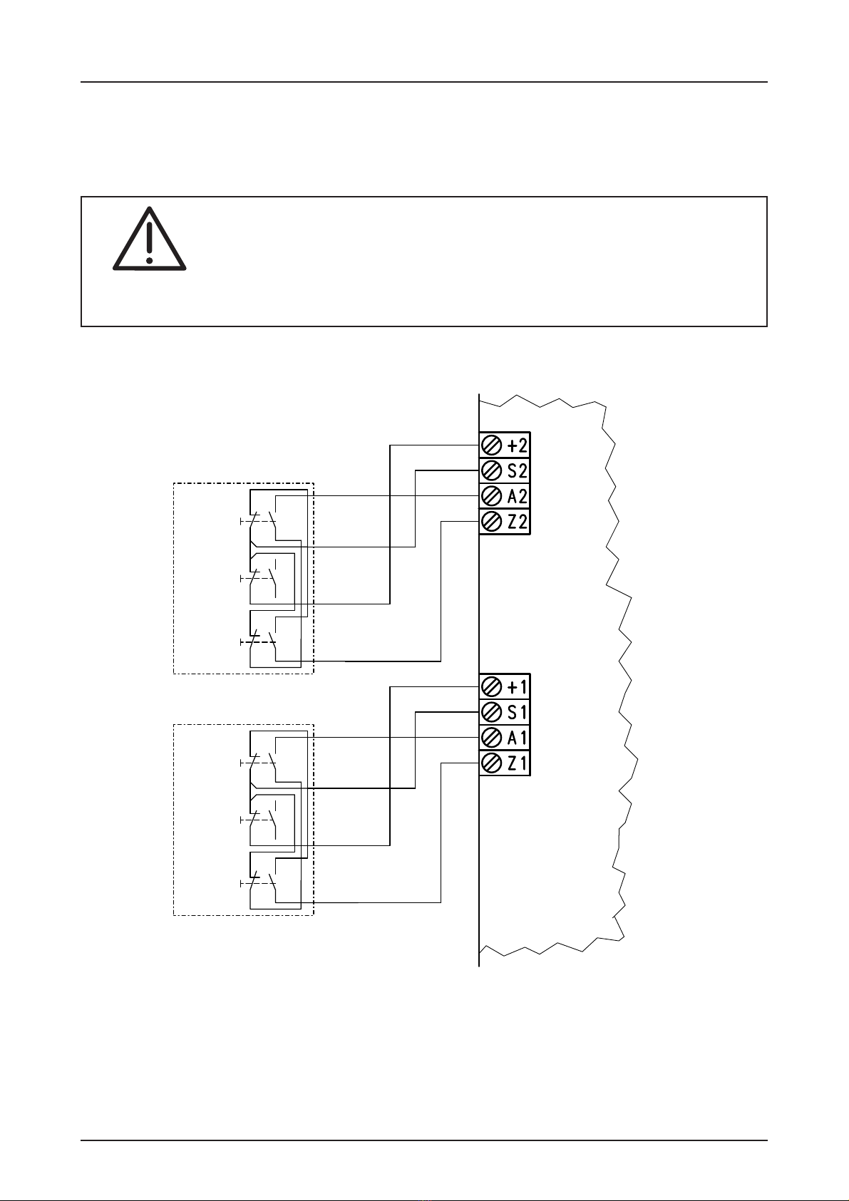
The control provides two potential free relay contacts, which can be used for several functions.
Functions can be programmed:
Relay contact 1 Relay contact 2
Fore-warning signal light Signal light green
no function Switch contact*
no function
* only possible when the intermediate stop is not required when using a mechanical limit.
When using DES all functions are available.
The relay contact will be supplied with no function programmed. The switch contact can be
loaded max.: Voltage 230V current 1A.
RELAY CONTACT
Fig. 1: Wiring diagram relay contact´s
R1
R2
Relais 2
Relais 1
page 17
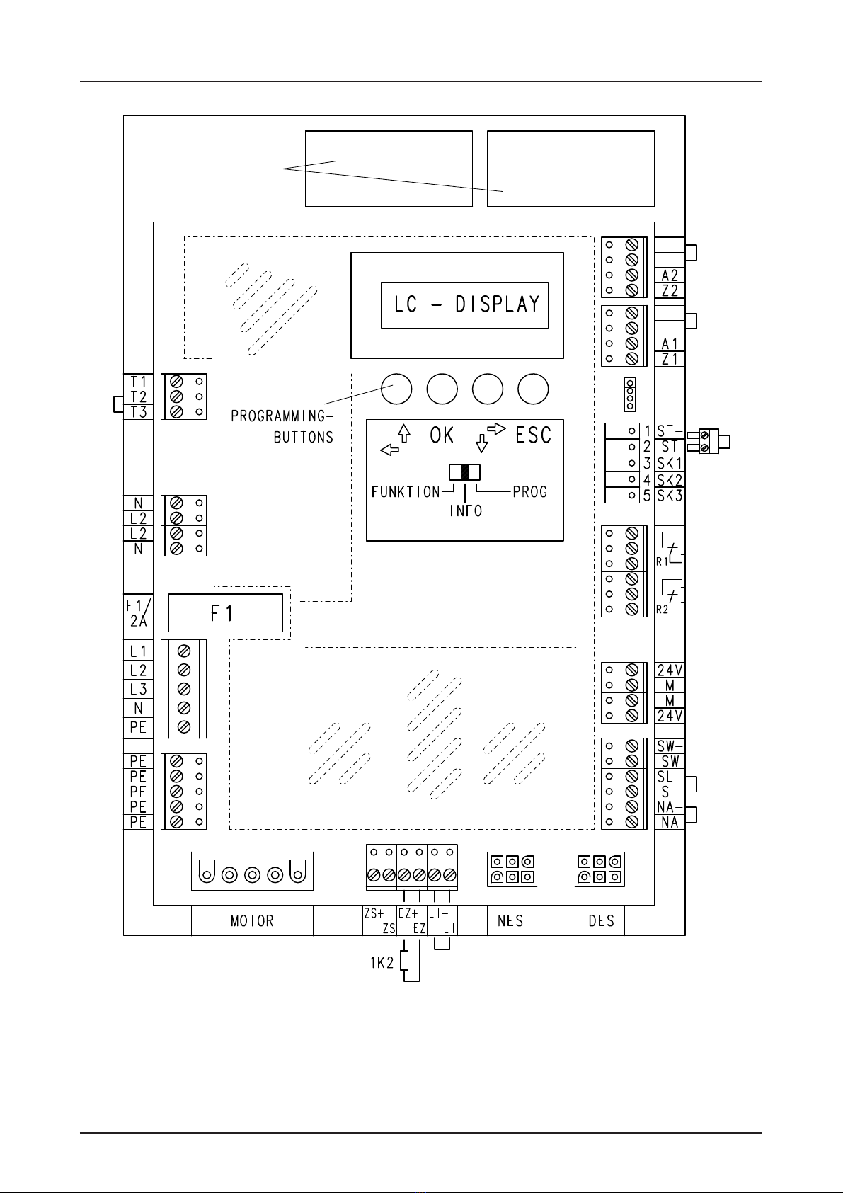
PCB PRINT OVERVIEW
S1
+1
S2
+2
<1
MODULE
POCKETS
FOIL-
KEYPAD

page 18
INITIALISATION
The control panel TS 980 is delivered with a 5 pole CEE plug and a foil keypad Open - Stop -
Close. The SELECTOR SWITCH is set in the position "Function".
After installation, during the set-up, an initialising program starts running, which recognises
DES (digital limits) or NES ( mechanical limits), this needs max 5 sec.
adjust limit
FUNCTION
INFO
PROG
FUNCTION
INFO
PROG
On initial installation the SELECTOR SWITCH must
be set to PROG
To move UP and DOWN in the program press
the arrowed button, language, door position or addi-
tional adjustment can be selected. Confirm selected
function with OK.
ÏÐ
Doorposition OK ?
Aux. Functions
ESCOK
ESCOK
Initial installation
display appears: Adjust limits
page 19
add. adjustments
Select Language OK?
ESCOK
Language selection
Select Language
D GB F
ESCOK
INITIALISATION
Selection of 3 languages integrated.
Set SELECTOR SWITCH to PROG, now using the
arrow buttons UP and DOWN choose SELECT
LANGUAGE and confirm with OK.
The display will show
D = German
GB = English
F = French
Move UP and DOWN with the arrowed buttons and
confirm the required language with OK.
The standard language delivered is GERMAN.
From now on:
To move UP and DOWN in the program press the arrowed buttons.
After each successful function is programmed, the display shows SET!

page 20
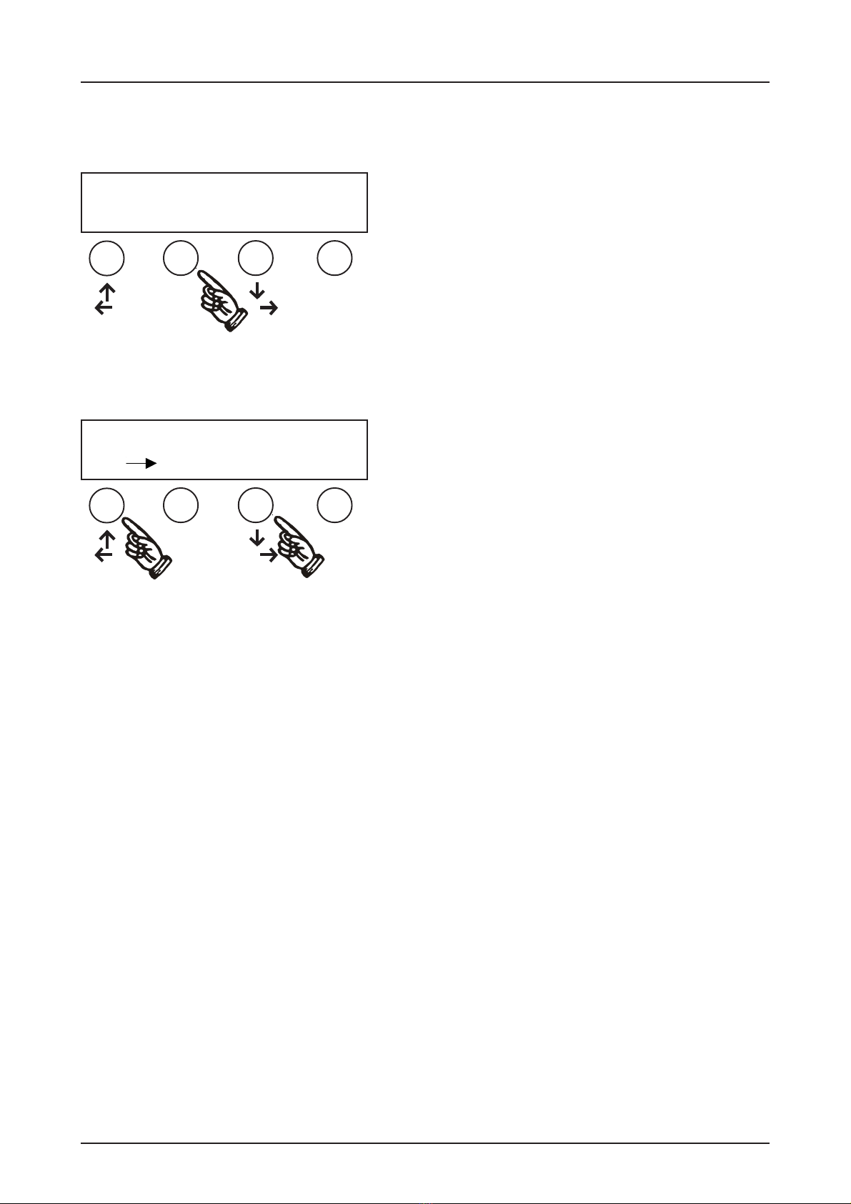
Doorposition OK ?
Aux. Functions
After PROG has been selected, the limits should be
adjusted. Confirm door position OK
Select with arrowbutton ÏÐ
Final open
adjust OK ?
Display appears, confirm OK?
To exit use ESC
Door OPEN >
Door CLOSE < OK ?
The control is now in the menu for setting the limits.
The arrow buttons UP and DOWN are used to move
the shutter in DEAD MAN MODE to the final open
position to set the limit S3. See mechanical
instruction, setting the limits. The final open
position must be confirmed by pressing the OK
button after S3 has been operated when the door
is moving.
To exit use ESC
Adjust the mechanical limits NES
ADJUSTMENT OF THE LIMITS/ BASIC-FUNCTION
ESCOK
ESCOK
ESCOK
Table of contents
Other Elektromaten Control Panel manuals


Popular Control Panel manuals by other brands


PS Engineering
PS Engineering PMA8000BT System installation and operation manual

Bosch
Bosch B5512 reference guide

Mitsubishi
Mitsubishi GT2715XTBA installation manual

versa
versa IUI-SOL- VT5 Series quick start guide

SANJIANG
SANJIANG SEC3002 Installation & commissioning manual

Chamberlain
Chamberlain 41A6345-1 owner's manual


