Elektromaten TS 959 User manual
Pos: 1.2 /BA_Module_ Manuell/Torsteuerung TS 959/01_Deckblatt_ 68073 @ 7\mod_1347867455 430_28.docx @ 762690 @ @ 1
aus
Installation instructions
Door control
TS 959
51171559_a_11_2012
Status: 07.11.2012
Pos: 1.3 /BA_Module_ Manuell/Torsteuerung TS 959/MAL_Seitenumbruc h @ 6\mod_1344937085969_0. docx @ 758205 @ @ 1

2
Pos: 2.2 /BA_Module_ Manuell/Torsteuerung TS 959/02_Leerseite_680 73 @ 7\mod_1347867522 263_28.docx @ 762705 @ @ 1
GfA-ELEKTROMATEN
Australia Pty Ltd
P.O. Box 267
Roseville 2069 NSW
Telephone: 02 9882 2782
Facsimile: 02 9882 2783
Email: [email protected]
Web: www.
g
fa-elektromaten.net
=== Ende der Liste für Textmarke inhalt3 ===

3
Pos: 3.2 /BA_Module_ Manuell/Torsteuerung TS 959/03_Inhaltsverz eichnis @ 6\mod_13448 67191501_28.docx @ 757614 @ @ 1
Table of contents
1General safety information .............................................................................................. 5
2Technical data ................................................................................................................ 6
3Mechanical installation .................................................................................................... 7
4Electrical installation ....................................................................................................... 8
Connection overview for connection cables ...................................................................... 9
Carrying out the electrical installation.............................................................................. 10
Mains supply ................................................................................................................... 11
Mains connection to control ............................................................................................ 11
Completion of electrical installation ................................................................................. 11
Overview of control ......................................................................................................... 12
5Initial operation of the control ........................................................................................ 13
DES: Rapid adjustment of final limit positions ................................................................. 13
NES: rapid adjustment final limit positions ...................................................................... 14
6Advanced electrical installation ..................................................................................... 15
External supply X1 .......................................................................................................... 15
Emergency stop X3 ......................................................................................................... 15
Relay contact X20 ........................................................................................................... 15
Control device X5 ............................................................................................................ 1 5
Spiral cable connection ................................................................................................... 15
7Programming the control ............................................................................................... 16
8Table of menus ............................................................................................................. 17
Operating mode .............................................................................................................. 17
Door positions ................................................................................................................. 17
Door function ................................................................................................................... 18
Safety functions .............................................................................................................. 18
Maintenance cycle counter ............................................................................................. 19
Readout of information store ........................................................................................... 20
Deleting all adjustments .................................................................................................. 20
9Safety devices .............................................................................................................. 21
X2: Input, door safety switch ........................................................................................... 21
X3: Input, emergency stop .............................................................................................. 21
10Description of functions ................................................................................................. 22
X1: Mains supply line for control and external supply ..................................................... 22

4
X5: Input, control device .................................................................................................. 23
Extended hold-to-run function ......................................................................................... 23
X20 potential-free relay contact ....................................................................................... 24
Force monitoring (DES only) ........................................................................................... 24
Travel time monitoring (NES only) ................................................................................... 25
Maintenance cycle counter .............................................................................................. 26
Short-circuit/overload display .......................................................................................... 26
Standby function ............................................................................................................. 2 6
11Status display ................................................................................................................ 27
12Explanation of symbols ................................................................................................. 31
13Declaration of Incorporation/Declaration of Conformity .................................................. 33
=== Ende der Liste für Textmarke inhalt2 ===
Symbols
Warning - Risk of injury or danger to life!
Warning - Danger to life through electrical current!
Note - Important information!
▶ Request - Required action!
Illustrations show example products. Deviations from the delivered product are possible.

5
Pos: 4.2 /BA_Module_ Manuell/Torsteuerung TS 959/04_Sicherheitshi nweise @ 6\mod_134486 7202506_28.doc x@ 75762 9 @ 1 @ 1
1General safety information
Specified normal use
The door control is intended for a power-operated door with a drive unit.
The safe operation is only guaranteed with normal specified use. The drive unit is to be
protected from rain, moisture and aggressive ambient conditions. No liability for damage
caused by other applications or non-observance of the information in the manual.
Modifications are only permitted with the agreement of the manufacturer. Otherwise the
Manufacturer’s Declaration shall be rendered null and void.
Safety information
Installation and initial operation tasks are to be performed by trained, skilled fitters only.
Only trained electrical craftsmen are permitted to work on electrical equipment. They must
assess the tasks assigned to them, recognise potential danger zones and be able to take
appropriate safety measures.
Installation work is only to be carried out with the supply off.
Observe the applicable regulations and standards.
Coverings and safety devices
Do not operate unless corresponding coverings and safety devices are fitted/installed.
Ensure that gaskets are correctly positioned and cable glands are correctly tightened.
Spare parts
Use only original spare parts.
Pos: 4.3 /BA_Module_ Manuell/Torsteuerung TS 959/MAL_Seitenumbruc h @ 6\mod_1344937085969_0. docx @ 758205 @ @ 1

6
Pos: 5.1 /BA_Module_ Manuell/Torsteuerung TS 959/05_Technische Da ten @ 6\mod_1344924152708 _28.docx @ 757670 @ 1 @ 1
2Technical data
Series TS 959
Dimensions W x H x D 155 x 380 x 80 mm
Assembly vertical
Vibration Assembly
free of vibration
Operating frequency 50/60 Hz
Supply voltage
1 N~220 V, PE
3 N~220-400 V, PE
3~220-400 V, PE
Output power for drive unit, maximum 3 kW
Backup fuse per phase, on-site 10-16 A
External mains supply:
(internal electronic backup fuse)
24 V DC
0.35 A
External mains supply: X1/L, X1/N
(backup fuse via F1 micro-fuse)
1 N~230 V
1.6
A
time-
la
g
Control inputs 24 V DC
type 10 mA
Type relay contact floating changeover
contacts
Loading of relay contacts,
ohmic/inductive
230 V AC
1 A
Control power consumption 10 VA
Temperature range Operation: -5..+40
Storage: +0..+50 C°
Humidity up to 93 %
non-condensing
Class of protection of housing IP65
Compatible GfA limit switch NES; DES
Pos: 5.2 /BA_Module_ Manuell/Torsteuerung TS 959/MAL_Seitenumbruc h @ 6\mod_1344937085969_0. docx @ 758205 @ @ 1
7
Pos: 6.1 /BA_Module_ Manuell/Torsteuerung TS 959/06_Mechanische_ Montage @ 6\mod_134492443 3864_28.docx @ 757688 @ 1 @ 1
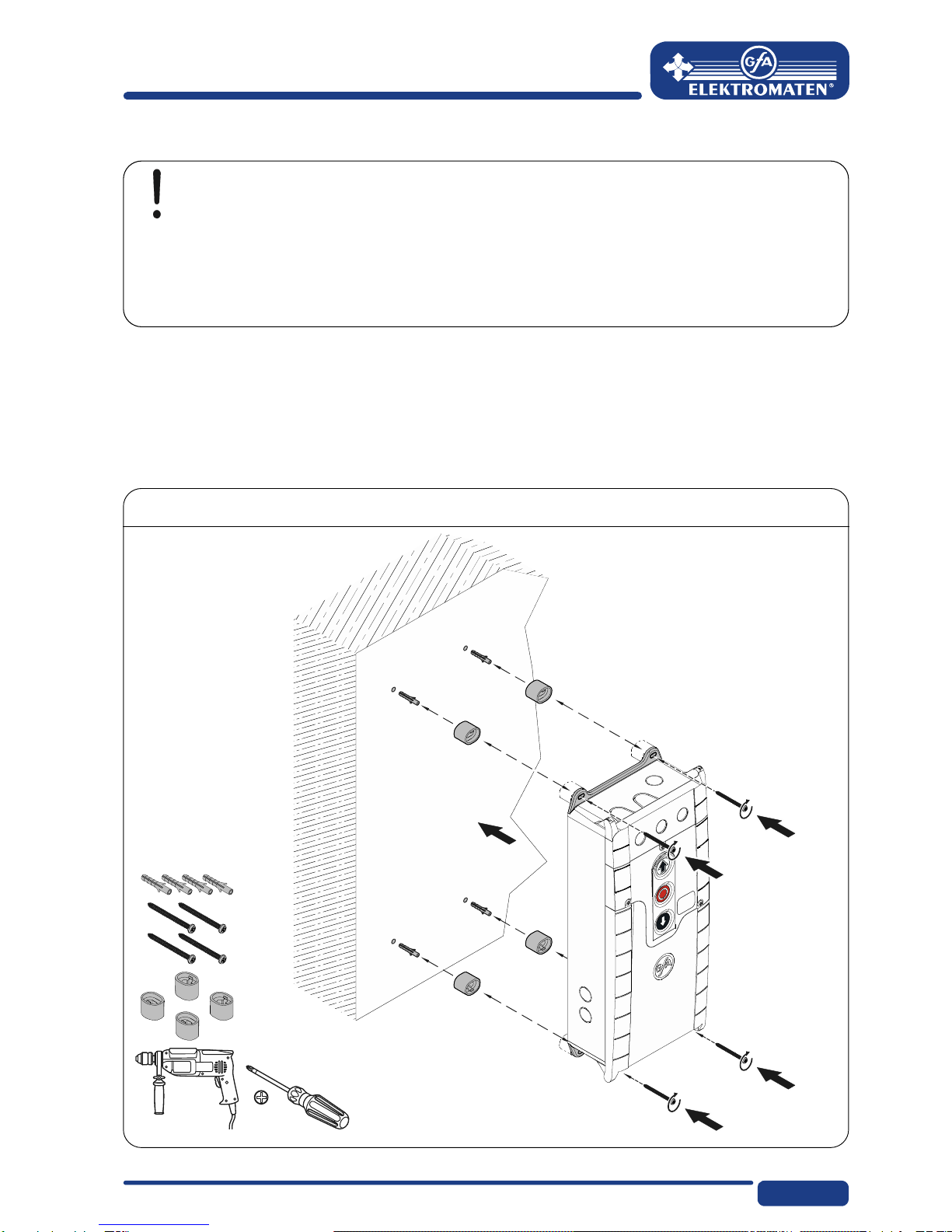
3Mechanical installation
Control installation!
Only use indoors
Mounting only on a level ground free of vibration
Only vertical mounting position permissible
Door must be visible from the assembly site
Prerequisites
The permissible loads of walls, mountings, connecting and transmission elements must not
be exceeded.
Mounting
The control is mounted via 4 elongated holes
Pos: 6.2 /BA_Module_ Manuell/Torsteuerung TS 959/MAL_Seitenumbruc h @ 6\mod_1344937085969_0. docx @ 758205 @ @ 1

8
Pos: 7.1 /BA_Module_ Manuell/Torsteuerung TS 959/07_Elektrisc he Montage @ 6\mod_13449244497 62_28.docx @ 757703 @ 122 2222 @ 1
4Electrical installation
Warning - Risk of electrocution!
Disconnect the cables (mains OFF) and check that they are voltage-free
Observe the applicable regulations and standards
Make a proper electrical connection
Use suitable tools
On-site back-up fuse and mains disconnector!
Connection to the indoor installation via an all-pole disconnector unit, with current
≥ 10 A as per EN 12453 (e.g. CEE plug connector, main switch)
Read installation instructions for drive unit!

9
Connection overview for connection cables
DES and NES
connection cables for motor DES connection cable for limit switch
MOT X13 Motor plug DES X12 Limit switch plug
Pin Core Term. Pin Core Term.
1 3 W Phase W 15/wh 1+24 V safety circuit
2 2 V Phase
V
26/bn 2Channel B (RS485)
3 1 U Phase U 37/gn 3Earth
4 4 N Neutral conductor (N) 48/ye 4Channel A (RS485)
5 PE PE 59/gy 5Safety circuit
610/pk 68-VDC main supply
Cam-limit connecting cable
NES X12 Limit switch plug
Pin Core Term.
1 5/wh 11 Limit switch potential of +24 V, wire link at X12 5, 7, 9, 11, 14
2 6/bn 12 S5 additional limit switch, testing or safety edge function
3 7/gn 6 S3, “Open” limit switch
4 8/ye 15 S6 additional limit switch, relay function
5 9/gy 8 S4, “Close” limit switch
6 10/pk 4 Safety circuit
10
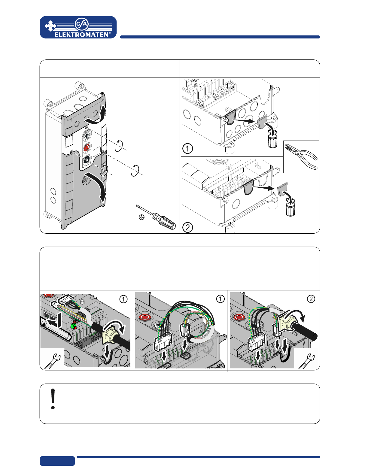
Carrying out the electrical installation
▶ Remove the covers. ▶ Open cable conduit ① or ②.
▶ Insert and connect control/drive connection cable in the open cable conduit ① (from
below) or ② (from above).
▶ Tighten cable gland.
Caution - Avoid damage to components!
Open cable conduit with suitable tool
Install cable entries and/or cable glands

11
Mains supply
3-phase current,
with neutral
conductor
3-phase current,
without neutral
conductor
1-phase
symmetrical
1-phase
asymmetrical
L2L3 NPE L2 L3 PE NPE
NPE
Mains connection to control
3
Completion of electrical installation
Connect any other control devices and/or safety devices.
Install and tighten cable entries and/or cable glands.
For initial operation of the control, leave the covers open.
12
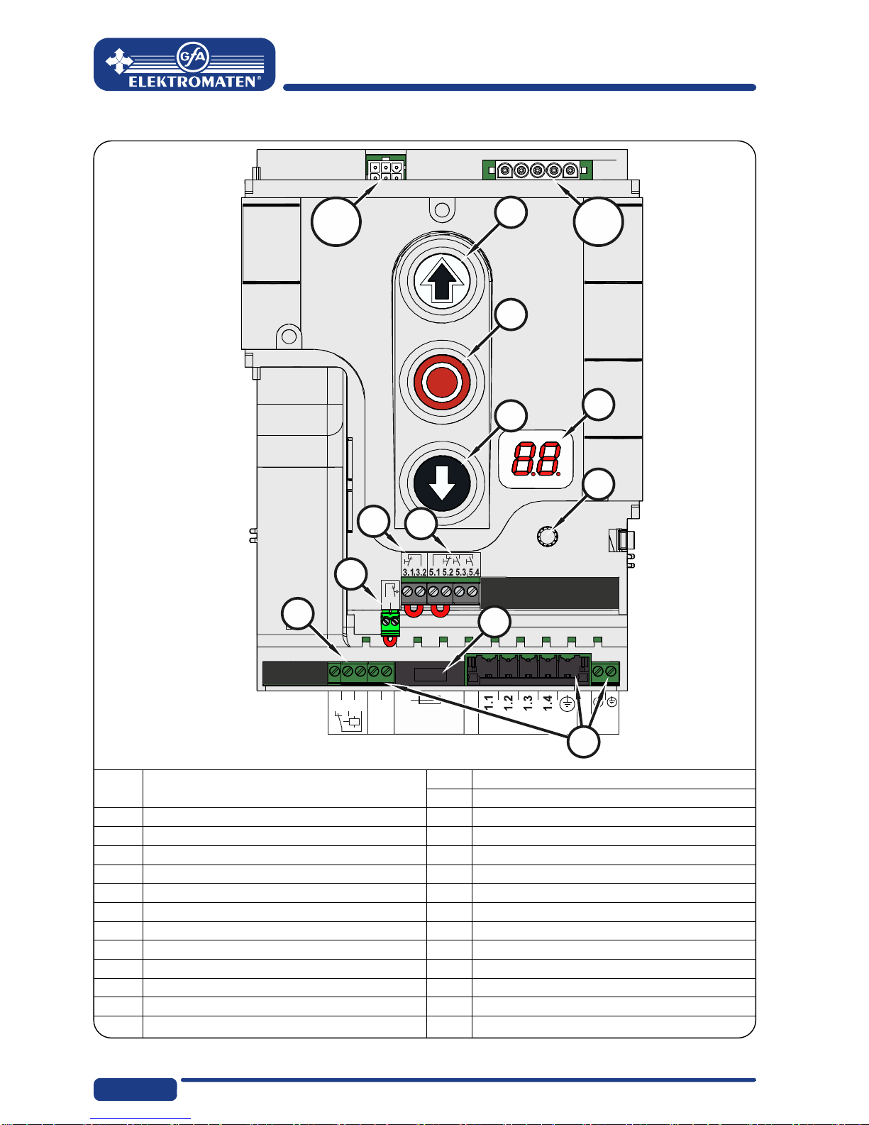
Overview of control
2.1
2.2
20.1
1.8
1.9
20.2
20.3
F1 = 1,6At
MOT
DES/
NES S11
S12
X20
X3
X2
X5
S
X1
F1
V1
S13
DES/
NES DES or NES limit switch socket X1 Mains supply
X2 Safety switch for door
F1 1.5-A micro-fuse with time delay X3 Emergency stop button
MOT Motor socket X5Control device, external three push button
S Selector switch X20 Potential-free relay contact
S11 “Open” button
S12 “Stop” button
S13 “Close” button
V1 Display
Pos: 7.2 /BA_Module_ Manuell/Torsteuerung TS 959/MAL_Seitenumbruc h @ 6\mod_1344937085969_0. docx @ 758205 @ @ 1
13
Pos: 8.1 /BA_Module_ Manuell/Torsteuerung TS 959/08_Inbetriebnah me (Schnelleinste llung) @ 6\mod_13449244643 83_28.docx @ 757718 @ 122 @ 1
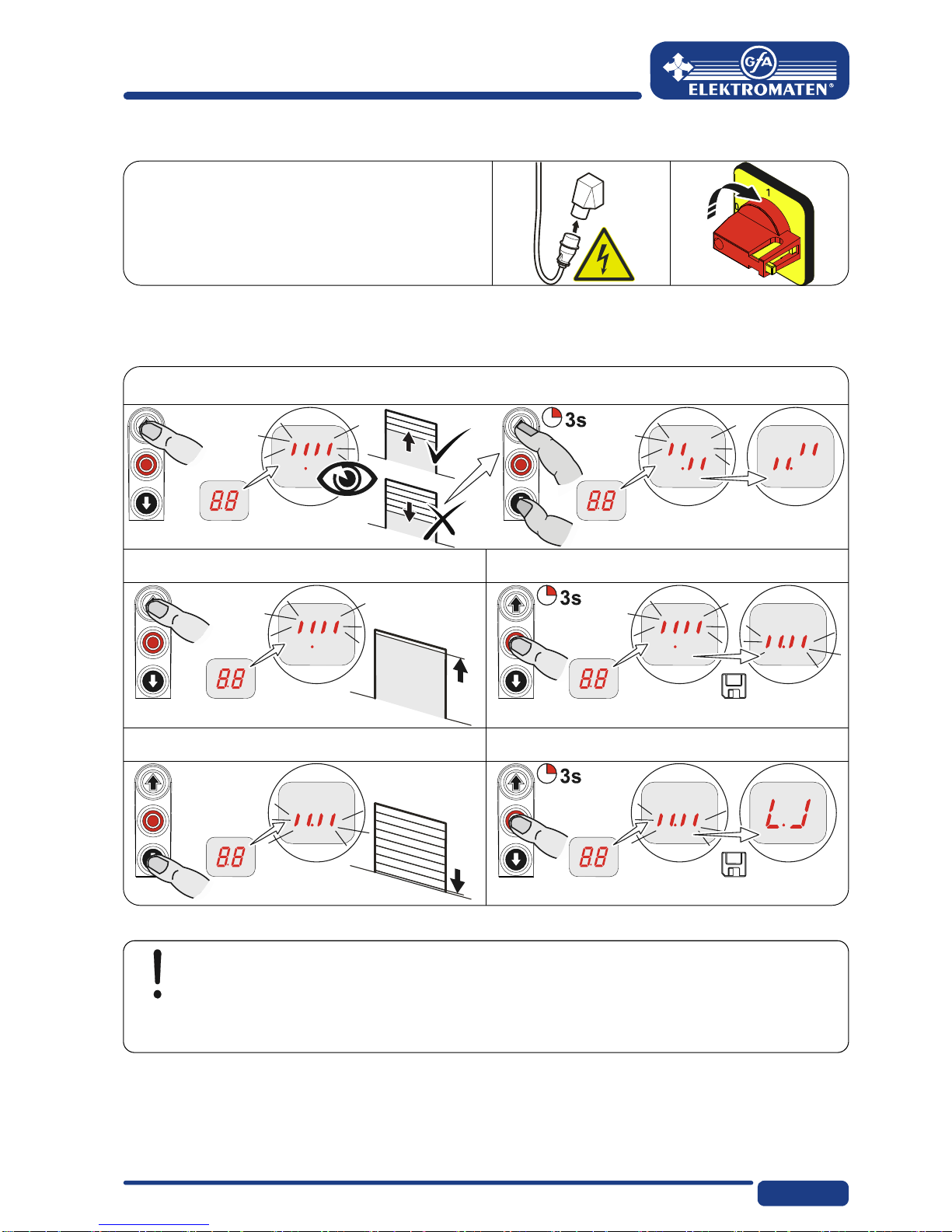
5Initial operation of the control
▶ Plug in or switch on mains supply line
DES: Rapid adjustment of final limit positions
1. Check rotating direction
2. Start OPEN final limit position 3. Save OPEN final limit position
4. Start CLOSE final limit position 5. Save CLOSE final limit position
Note!
Rapid adjustment is complete, "Hold-to-run" door operating mode active
Change of OPEN/CLOSE final limit positions under menus "1.1" to "1.4"
14
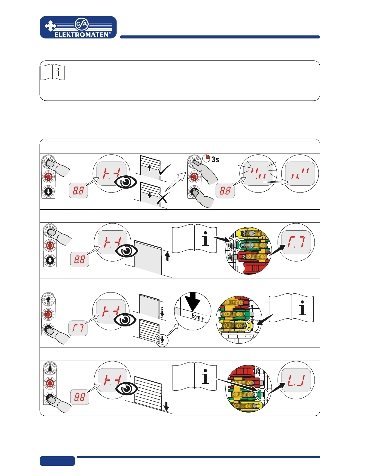
Read the drive unit mounting manual!
Adjust the cam limit switch, see drive unit mounting manual
NES: rapid adjustment final limit positions
1. Check rotating direction
2. Move to OPEN final limit position and adjust S3 OPEN limit switch
3. Move to 5 cm in front of the CLOSED final limit position and set S5 pre-limit
4. Move to CLOSED final limit position and set S4 CLOSED limit switch
Pos: 8.2 /BA_Module_ Manuell/Torsteuerung TS 959/MAL_Seitenumbruc h @ 6\mod_1344937085969_0. docx @ 758205 @ @ 1
15
Pos: 9.1 /BA_Module_ Manuell/Torsteuerung TS 959/09_Erweiter teel ektrische Insta llation @ 6\mod_13449244 77714_28.docx @ 757733 @ 1 @ 1
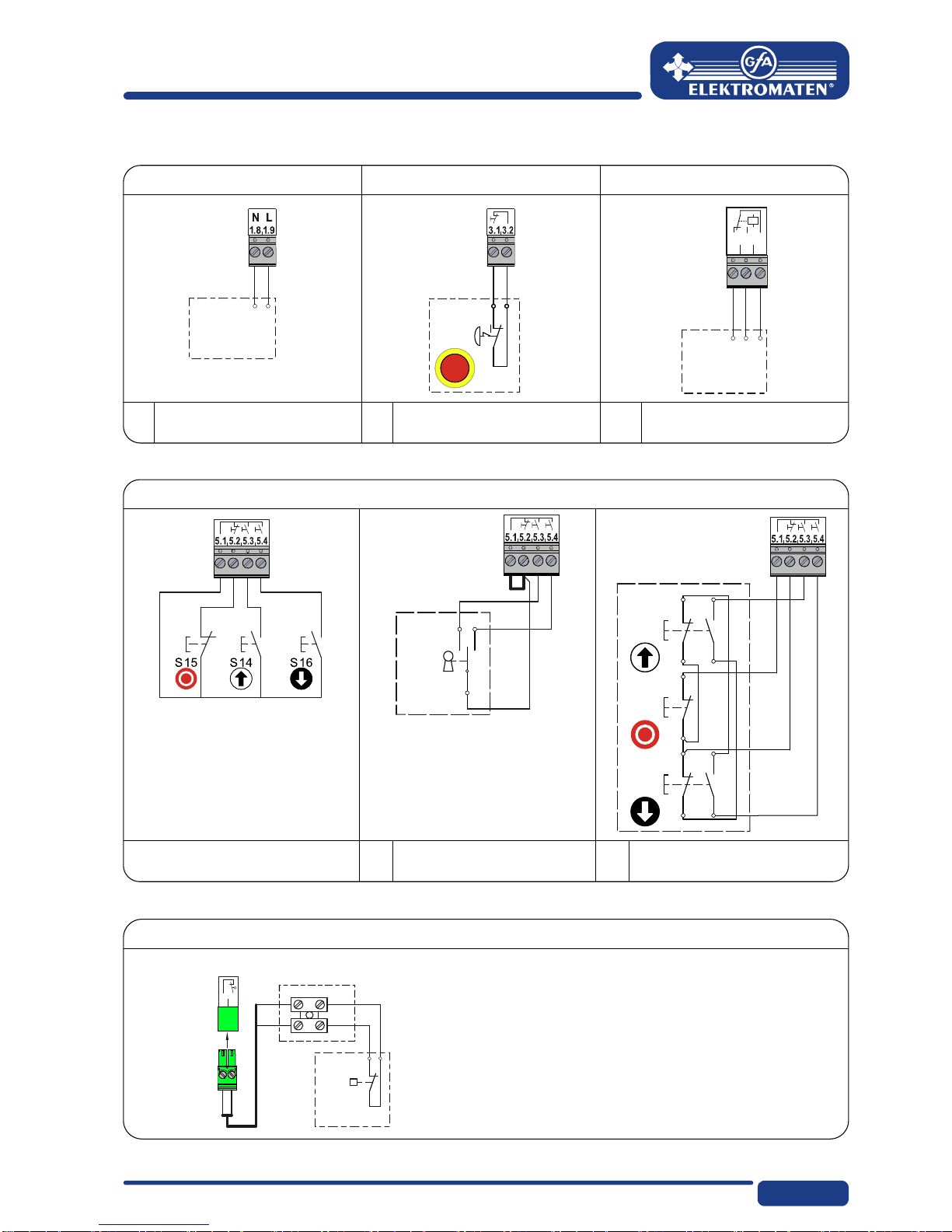
6Advanced electrical installation
External supply X1
Emergency st op X3
Relay contact X20
External supply X1 Emergency stop X3 Relay contact X20
X1
A1
X3
A2
2
1
S15
X20
20.1
20.2
20.3
A16
A
1 External device
A
2 Control device
A
16 Relay
Emergency stop
Control device X 5
Control device X5
X5
P
1
S17
2
A4
X5
4
3
2
1
S14
4
3
2
1
S16
2
1
S15
A6
X5
A
4 Key-switch
A
6Three push button
Open/Close locked
Spiral cable connec tion
Spiral cable connection
Door safety switch
ST+
ST
A20
2
1
S30/
S31
12
2.1
2.2
X2
1
2
A20 Junction box switch
S30 Pass door switch (NC)
S31 Slack-rope switch (NC)
Pos: 9.2 /BA_Module_ Manuell/Torsteuerung TS 959/MAL_Seitenumbruc h @ 6\mod_1344937085969_0. docx @ 758205 @ @ 1
16
Pos: 10.1 /BA_Module_ Manuell/Torsteuerung TS95 9/10_Programmier ung der Steuerung @ 6\mod_1 344924529099_28.doc x@ 757 748 @ 1 @ 1
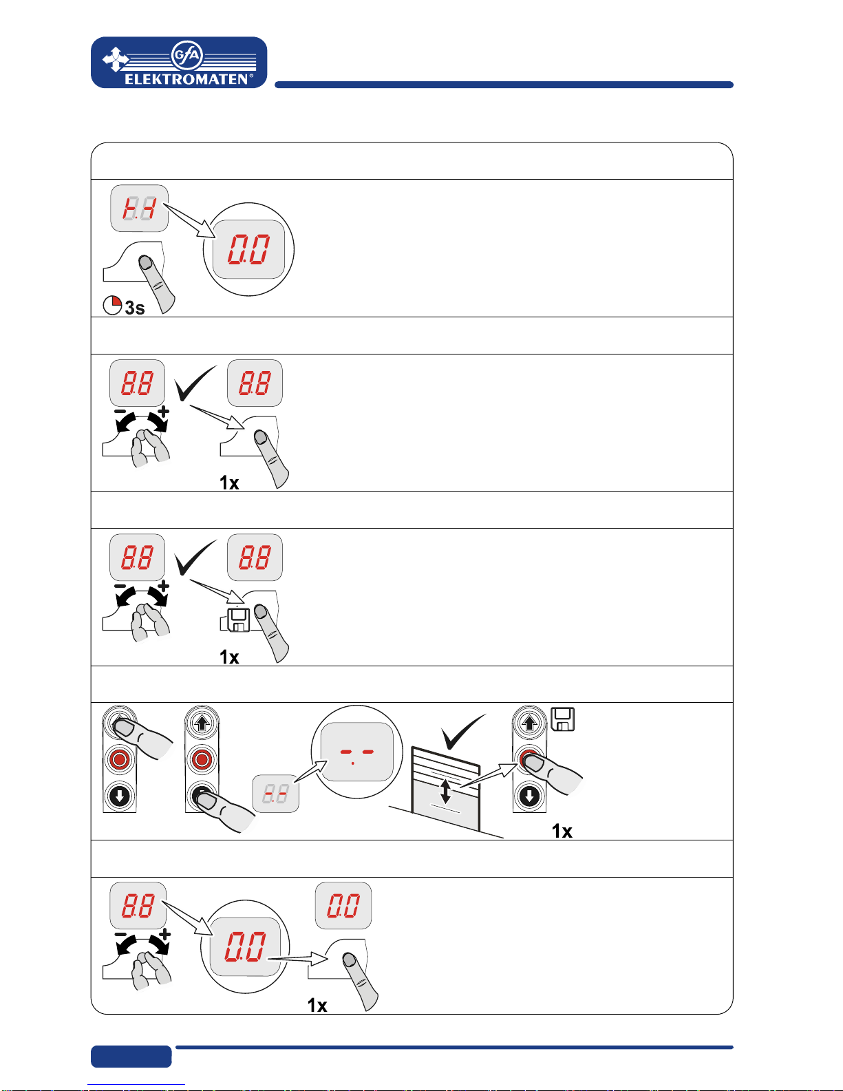
7Programming the control
1. Only program after rapid adjustment of final limit positions!
2. Select and confirm the menu
3.a) Set and store functions
3.b) Set and save (DES) positions
4. Exit programming
Pos: 10.2 /BA_Module_ Manuell/Torsteuerung TS95 9/MAL_Seitenumbruc h @ 6\mod_1344937085969_ 0.docx @ 758205 @ @ 1
17
Pos: 11.1 /BA_Module_ Manuell/Torsteuerung TS95 9/11_Parameterei nstellungen @ 6\mod_13 44924544071_28.doc x@ 757763 @ 1 @ 1
8Table of menus
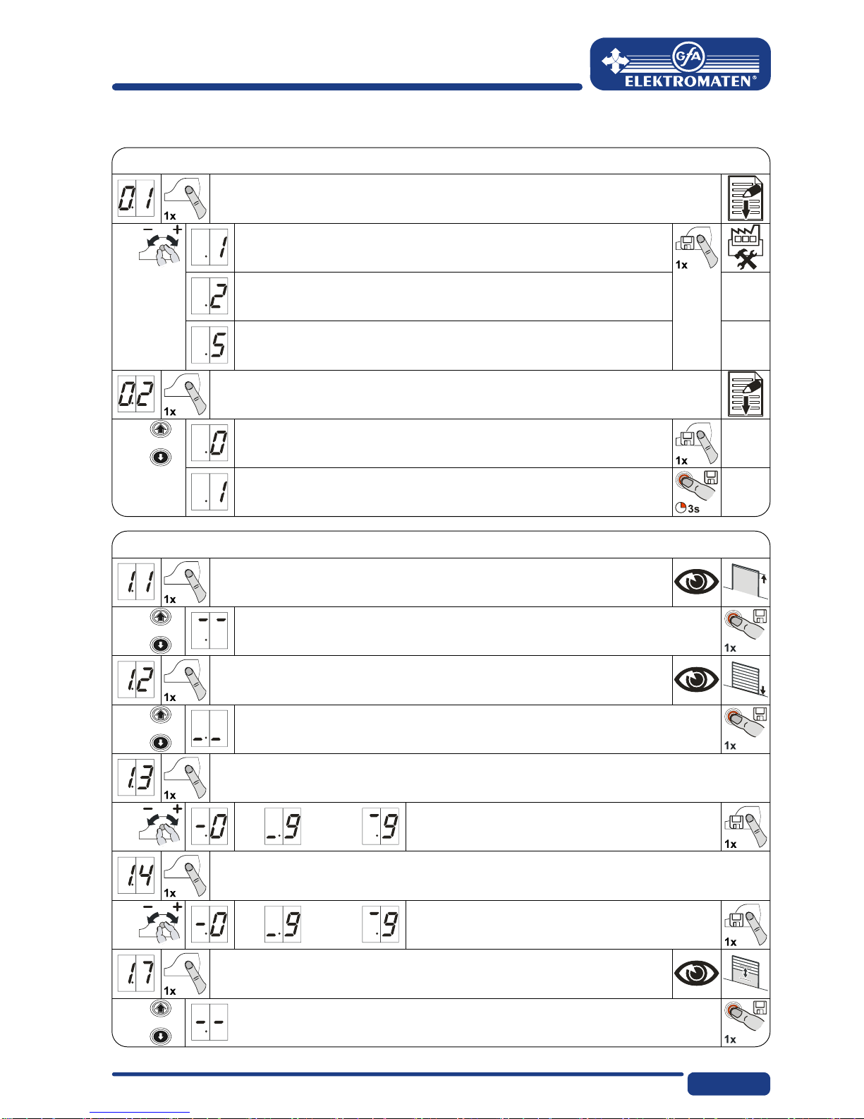
Operating mode
Operating mode
Door operating mode
OPEN
CLOSE
Hold-to-run
Hold-to-run
OPEN
CLOSE
Self hold
Hold-to-run
Extended hold-to-run control
Turning direction
Maintain turning direction
Change turning direction
Door positions
Door positions
OPEN final limit position coarse correction
OPEN/CLOSE door movements
CLOSE final limit position coarse correction
OPEN/CLOSE door movements
OPEN final limit position fine-correction
Without door movements,
[ + ] correct in OPEN
[ – ] correct in CLOSE
CLOSE final limit position fine-correction
Without door movements,
[ + ] correct in OPEN
[ – ] correct in CLOSE
Position Relay 1 switching point
Select relay function via menu 2.7
OPEN/CLOSE door movements
With NES: Set additional limit switch
18
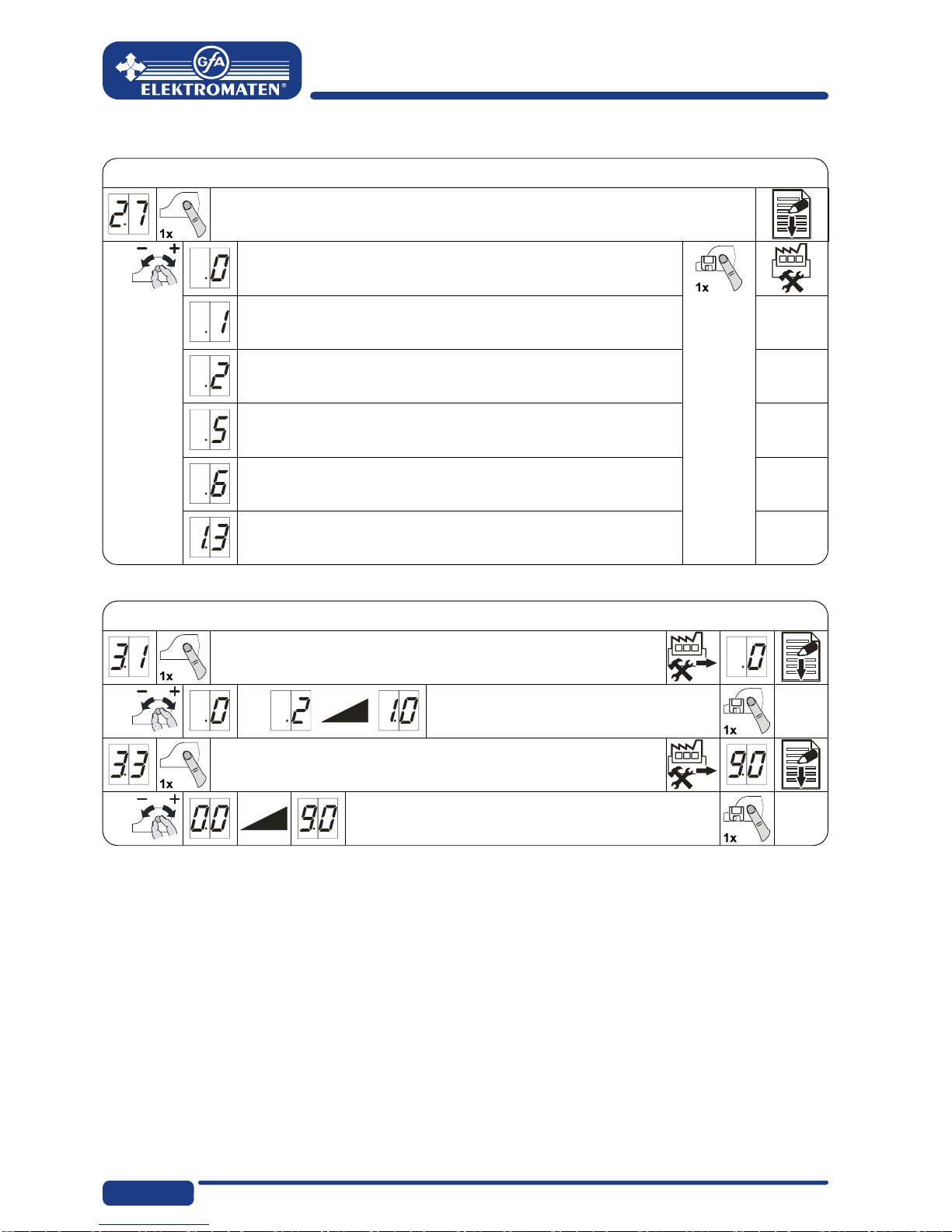
Door function
Door function
Relay function on X20
Teach-in door positions via menu 1.7 (DES only)
Off
Impulse signal
for 1 second
Permanent signal
Red lamp, permanent light during door movements
OPEN final limit position 3 seconds permanent light
CLOSE final limit position 3 seconds permanent light
Red lamp, permanent light during door movements
OPEN final limit position 3 seconds permanent light
CLOSE final limit position Off
Clearance dock leveller
Active at OPEN final limit position only
Safety functions
Safety functions
Force monitoring (DES)
0 = Off
adjustable from 2 % to 10 % overload
Travel time monitoring (NES)
0 = Off
0 to 90 seconds
19
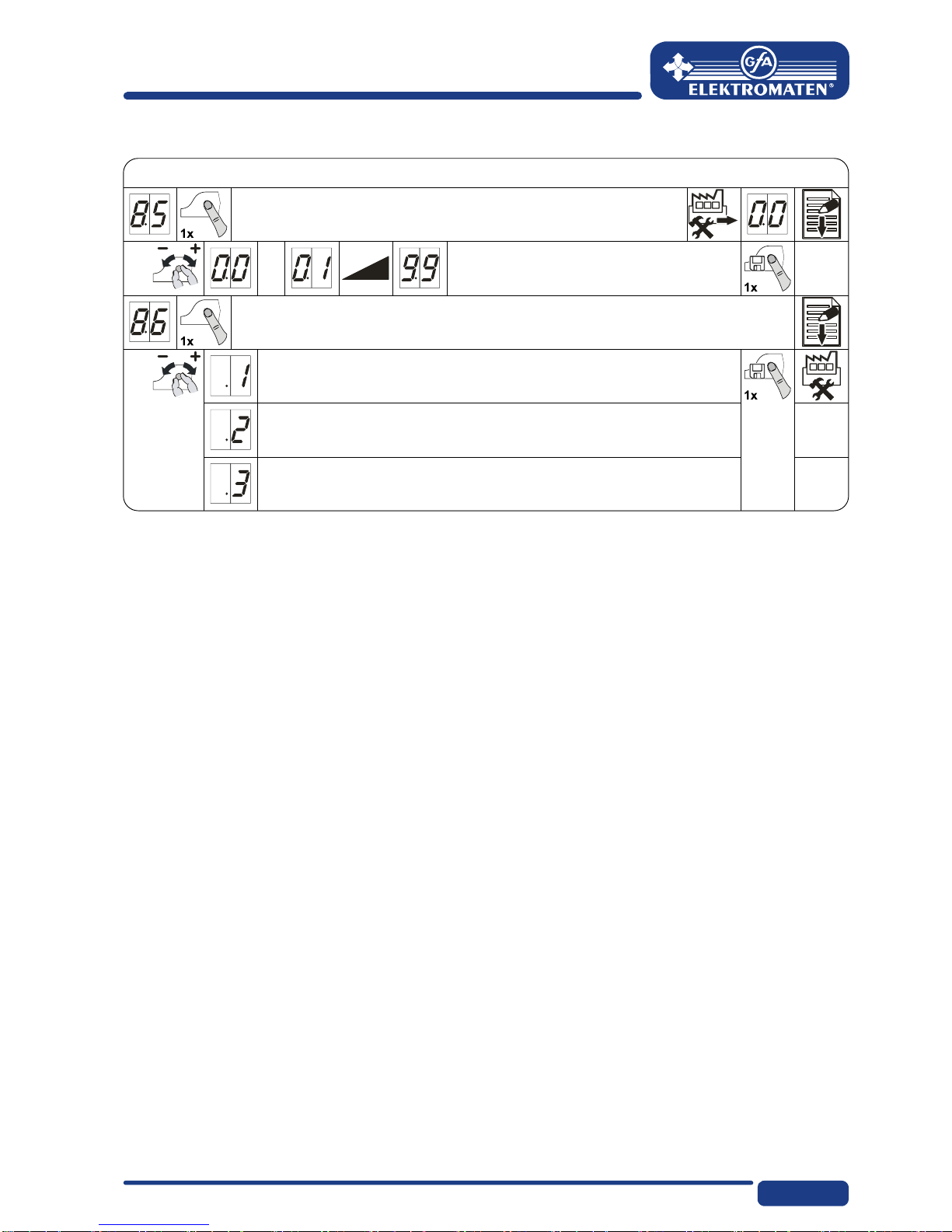
Maintenance cyc le counter
Maintenance cycle counter
Maintenance cycle preselection
01-99 corresponds to 1,000 to 99,000 cycles
Cycles are counted down
Reaction on reaching zero
"CS" display with set value of maintenance cycle
Changeover to hold-to-run and "CS" display with set value of
maintenance cycle
Changeover to hold-to-run and "CS" display with set value of
maintenance cycle with reset option for 500 cycles and activation by 3-
second stop button

20
Readout of inform ation stor e
Readout of information store
Cyclus counter reading
7-digit number
M HT ZT V H Z E
Cyclus counter reading in divisions of ten consecutively
M
HT
=
=
1,000,000
100,000 ZT
T
=
=
10,000
1,000 H
Z
=
=
100
10 E= 1
Last fault
Display change of the last fault, maximum 6 faults
Cyclus counter reading of the last programming change
7-digit
M HT ZT V H Z E
Cyclus counter reading in divisions of ten consecutively
M
HT
=
=
1,000,000
100,000 ZT
T
=
=
10,000
1,000 H
Z
=
=
100
10 E= 1
Firmware version
The firmware version of the control is displayed.
Deleting all adj ustments
Deleting all adjustments
Deleting all adjustments
All (factory setting)!
Except for cyclus counter reading
Pos: 11.2 /BA_Module_ Manuell/Torsteuerung TS95 9/MAL_Seitenumbruc h @ 6\mod_1344937085969_ 0.docx @ 758205 @ @ 1
Table of contents
Other Elektromaten Door Opening System manuals

Popular Door Opening System manuals by other brands


Synergy Hardware
Synergy Hardware S900 Series Fixing instructions

Dorex
Dorex 441C Series installation instructions

Allegion
Allegion Von Duprin 98 Series installation instructions

GEZE
GEZE Powerdrive PL-HT Pre-installation instructions

Norton
Norton 1600 Series installation instructions

Dorma
Dorma 96 GSR-EMF Mounting instructions

Kesseböhmer
Kesseböhmer eTouch DISPENSA operating instructions

ECO Schulte
ECO Schulte FH842 Assembly instructions

Dormakaba
Dormakaba RTS88 installation instructions

LCN
LCN 4050AT installation instructions

Tormax
Tormax iMotion 1301 Instructions for use

Von Duprin
Von Duprin 98/9927 installation instructions