Aprimatic Buongiorno User manual

- 24 -
English
Introduction
1
1.1 Glossary and abbreviations ................................................................................................................................................................25
1.2 Safety notices ......................................................................................................................................................................................25
Safety precautions
2
2.1 General safety precautions.................................................................................................................................................................26
2.2 Installer’s requisites .............................................................................................................................................................................26
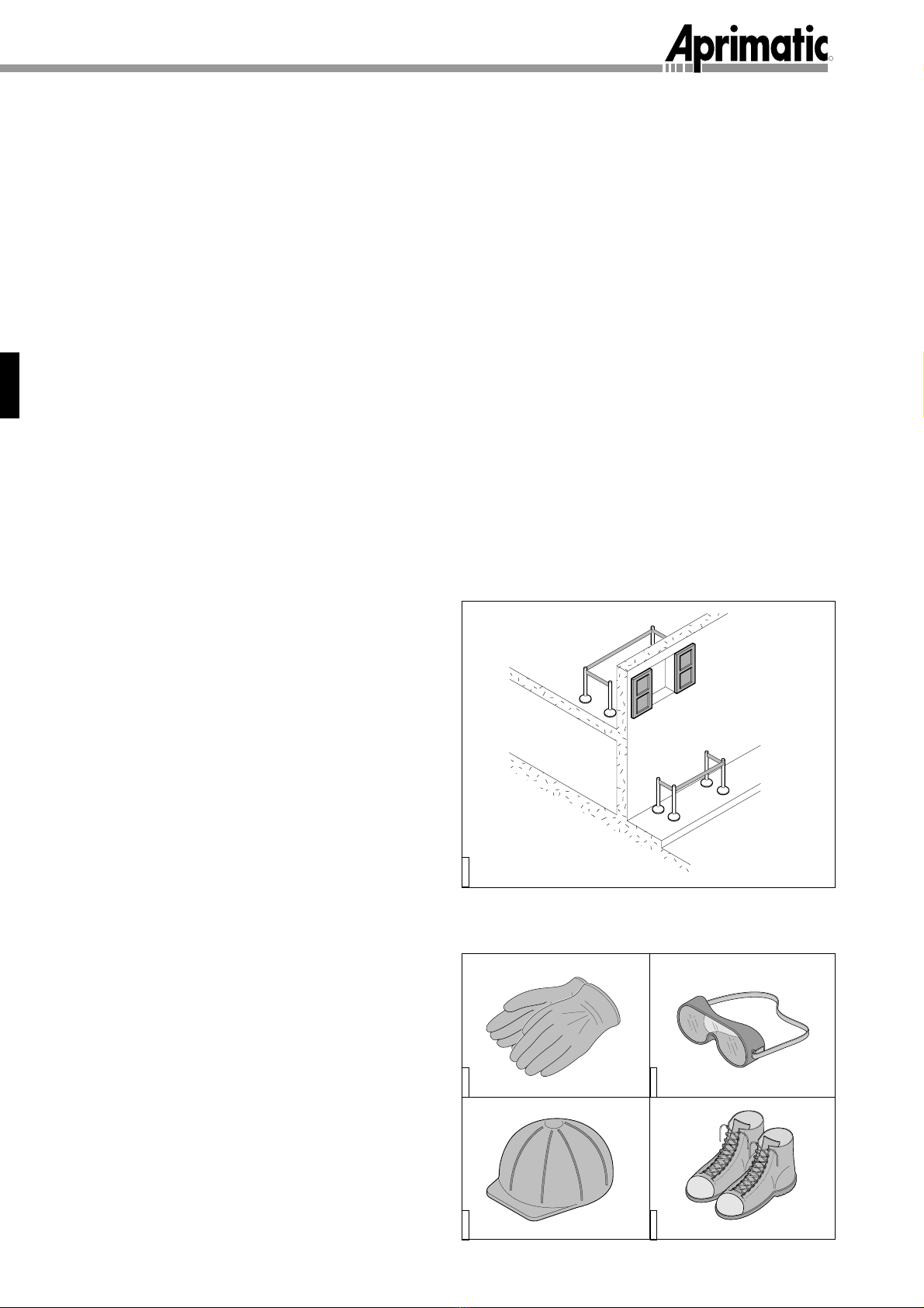
2.3 Working clothes...................................................................................................................................................................................26
2.4 Permitted uses ....................................................................................................................................................................................27
3
3.1 General description.............................................................................................................................................................................28
3.2 Technical characteristics .....................................................................................................................................................................29
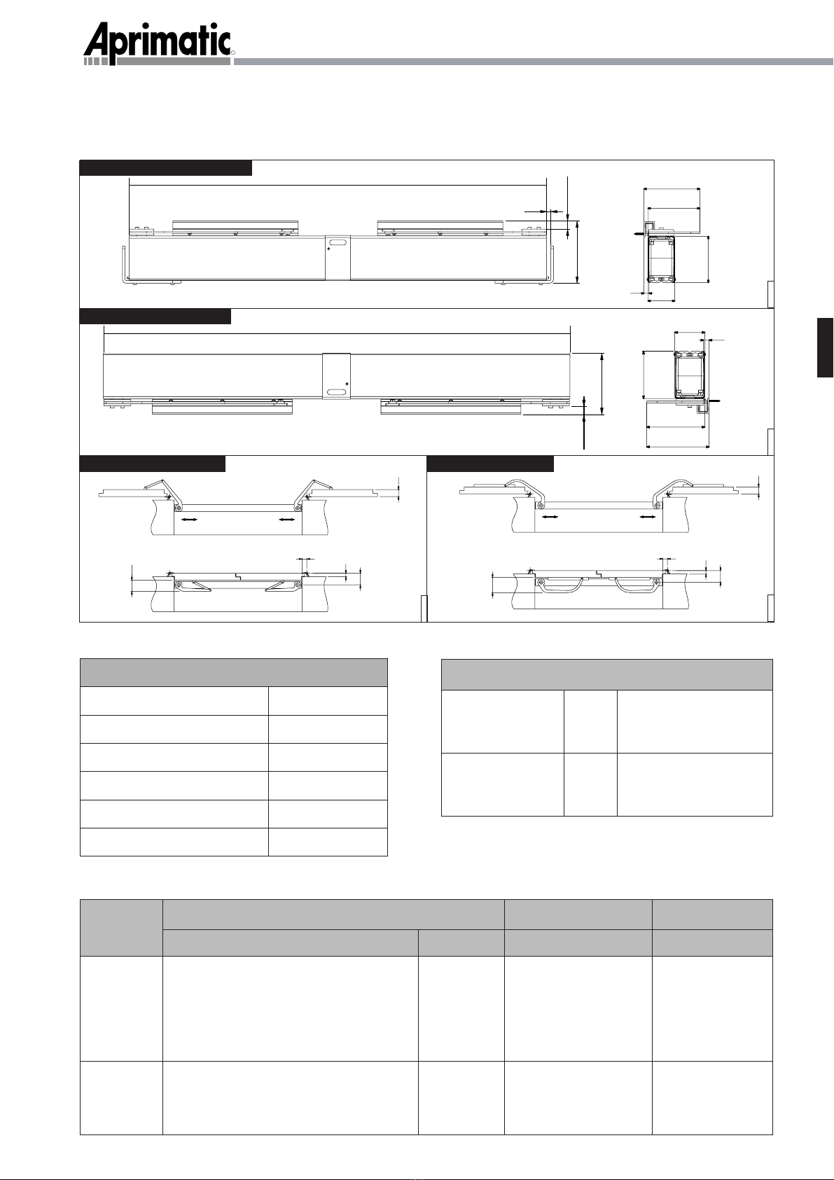
3.2.1 Overall dimensions..............................................................................................................................................................................29
3.2.2 Technical data .....................................................................................................................................................................................29
3.2.3 Application field ...................................................................................................................................................................................30
3.3 Preliminary operations ........................................................................................................................................................................30
3.3.1 Mounting tools .....................................................................................................................................................................................30
3.3.2 Checking the electrical installation .....................................................................................................................................................31
3.3.3 Preliminary checks..............................................................................................................................................................................31
4
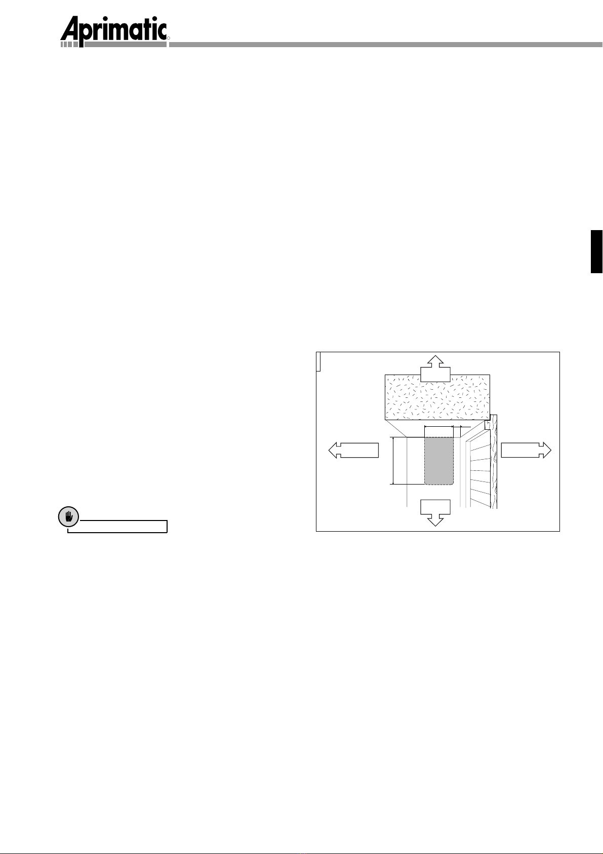
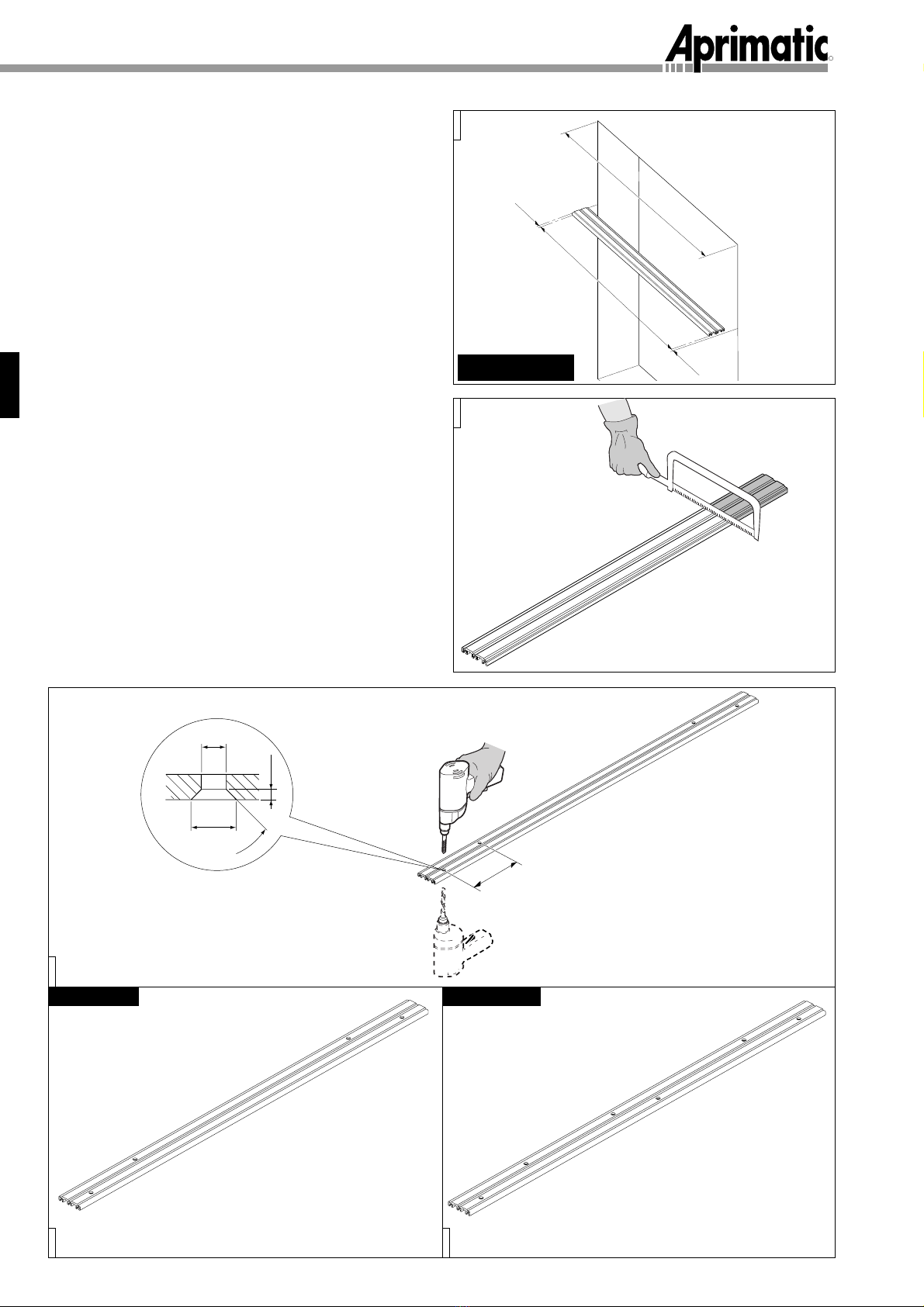
4.1 Assembly on lintel ...............................................................................................................................................................................32
4.1.1 Installing the geared motor ................................................................................................................................................................34
4.1.2 Positioning the geared motors ...........................................................................................................................................................35
4.1.3 Installing the control unit .....................................................................................................................................................................36
4.2 Cantilevered assembly........................................................................................................................................................................38
4.3 Electrical connections ........................................................................................................................................................................40
4.3.1 Useful advice.......................................................................................................................................................................................40
4.3.2 Connecting the motor cables..............................................................................................................................................................40
4.3.3 Connecting the control accessories ...................................................................................................................................................40
4.3.4 Connection to the power network.......................................................................................................................................................40
4.3.5 Programming the functioning..............................................................................................................................................................41
4.4 Checking the functioning ....................................................................................................................................................................42
4.4.1 Local control functioning .....................................................................................................................................................................42
4.4.2 Centralised control functioning ..........................................................................................................................................................42
4.4.3 Obstacle recognition ...........................................................................................................................................................................42
4.5 Mounting the casing............................................................................................................................................................................42
4.5.1 Version with electric stop ....................................................................................................................................................................43
4.5.2 Version without electric stop ...............................................................................................................................................................44
General features
Installation
Index/Introduction
5
5.1 Notes for the use .................................................................................................................................................................................45
5.1.1 What to do in case of power failure ....................................................................................................................................................45
Notes for the user

- 25 -
R
English
Introduction1
1.1 GLOSSARY AND ABBREVIATIONS
This paragraph lists uncommon terms or terms having a meaning other than the common one as well as the
abbreviations contained in the manual.
The uncommon terms are::
• INTERVENTION ZONE zone circumscribing the area of installation where the presence of an exposed person
may result in risks for the safety and the health of this person (Annex I, 1.1.1 Directive 89/392/EEC);
• EXPOSED PERSON any person standing completely or partially within a dangerous area (Annex I, 1.1.1
Directive 89/392/EEC);
• INSTALLER person charged with the installation, operation, adjustment, maintenance and transport of the
device (Annex I, 1.1.1 Directive 89/392/EEC);
• RESIDUAL RISK danger that could not be eliminated or sufficiently minimized during the designing phase.
The abbreviations are:
• Cap. = Chapter
• Par. = Paragraph
• Pag. = Page
• Tab. = Table
• Min. = Minimum
• Max. = Maximum
• Fig. = Figure
1.2 Safety notices
Warning
!
The notices preceded by this symbol provide information, provisions or procedures that, when not strictly
observed, may result in injury, death or long-term risks for people or the environment.
Caution
Thenotices preceded bythis symbol provideproceduresor practical advicethat,when not strictlyobserved,
may result in serious damage to the machine or the product.
Information
The notices preceded by this symbol provide important information: the non-compliance with such
instructions voids the manufacturer’s guarantee.

- 26 -
R
English
2.1 GENERAL SAFETY PRECAUTIONS
Beforeany operation, theinstallershall read thismanualthoroughly.In particular,heshall obeyallsafetyprecautions
listed below:
• Delimit the intervention zone with barriers to prevent non-authorized people from entering the area. If the
installation is done on frames facing pavements or roads, also the area underneath the intervention zone shall
be delimited to make sure that passers-by cannot get injured in the case of accidental fall of objects.
• Do not leave the intervention zone unattended.
• The intervention zone shall be free from hindrances, well-lit and with non-slip floor.
• Use only type-approved means in good conditions.
• Disconnect all power sources before installation and maintenance.
• Do the interventions according to the manufacturer’s instructions.
• The installer must check the installation and the proper functioning of the appliance.
• After installation, clean the intervention zone thoroughly and collect the wastes into special containers suitable
for differentiated refuse collection.
• Periodically check the proper functioning of the operator. Check it at regular intervals of maximum 12 months.
• Use only genuine spare parts
Safety precautions
2
2.3 WORKING CLOTHES
To work in full compliance with the safety regulations:
• wear type-approved working clothes and personal
protection equipment (working shoes, protection
goggles, gloves and hard hat);
• during assembly or adjustment operations, the
installer must use harnesses suitably anchored to
fixed elements to prevent serious injury in the case
of accidental fall;
• do not wear objects that may get caught (ties,
bracelets, necklaces, etc.).
2.2 INSTALLER’S REQUISITES
The installation ofAprimatic products shall be entrusted
to qualified technicians having the necessary technical
skill.
The operator shall meet the following criteria:
• He shall be attentive and scrupulous and observe
the safety precautions and the environment.
• He shall abstain from working under the influence of
drugs or alcoholic drinks that may alter or reduce
his quickness of reflexes.
AP009001
AP009060
AP009059
AP009061AP009062

- 27 -
English
Safety precautions
2.4 PERMITTED USES
The BUONGIORNO operator has been designed to automate the motion of single or double-wing shutters regardless
of the material they are made of (wood, aluminium, PVC) provided they fall within the dimensional limits (surface,
width, weight) indicated in Table 3 section 3.2.3.
Operator functions are controlled by an electronic unit which operates in one of the following modes: “man presence”;
semi-automatic; radio remote control.
WARNING. The semi-automatic and radio remote control modes must be controlled by appliances or devices
specially dedicated and manufactured by APRIMATIC to be combined with BUONGIORNO; in this case,
special connections for the use of additional safety devices (photocells, sensible bars, etc.) will be provided
to complete the installation.
Warning
!
• The Buongiorno operator has not been designed for work in potentially explosive environments.
• The use of the product for purposes other than those permitted is expressly forbidden.
• Do not tamper with or modify the product.
• The Buongiorno operator is not suitable for installation in environments directly exposed to rain.
Caution
The operator cannot be regarded as a supporting or safety element of the shutter; the shutter must be
equipped with suitable supporting and safety means.

- 28 -
R
English
3.1 GENERAL DESCRIPTION
The automatic operator consists of the following main components:
A - Electromechanical geared motors
Powered at 24V D.C. by the control unit (B) they transmit the motion to the thrust arms (C, D,)
B - Electronic control unit
By a built-in transformer, it converts 230V A.C. into 24V D.C. for the operation of geared motors (A). It also
controls the wing delay, the current absorbed by the limit switch and allows for the connection of optional
devices.
According to the type of shutter and the chosen assembly, APRIMATIC offers the following accessories::
C - Curved brackets
(see Aprimatic S.p.A price-list)
Recommended for the installation on shutters with a flat surface suitable for the mounting of the sliding
guides necessary for the bracket operation.
D-Articulated brackets
(see Aprimatic S.p.A price-list)
Recommended in case of uneven shutters or shutters that, for structural reasons, do not allow for a correct
mounting of curved brackets (C).
A
B
A
B
A
C
D
AP009004
Features
3
AP009003
AP009005
Single-wing
Double-wing

- 29 -
R
3.2 TECHNICAL CHARACTERISTICS
3.2.2 Technical data
3
3.2.1 Overall dimensions
3.2.3 Application field
Features
AP009065
AP009064 AP009071
9,5
3
4
6
10
13
10
6
3
4
430÷1500 130,5
12
10
18,6
142,6
62,8
121,4
103,4
AP009008
Cantileveled assemly
18,6
43
0÷1500
136,6
130,5
12
62,8
121,4
103,4
Assembly on lintel
Articulated brackets Curved brackets
Power supply 230 V A.C.
Motor voltage 24 V D.C.
Motor power 4,2 W
Gear motor torque 40 Nm
Operation speed 180° in 18 sec.
Working temperature -20°C ÷ +50°C
Window wing 0,8 m2 constant wind 35 Km/h
French window 1,5 m2 constant wind 25 Km/h
wing
Tab. 2 Resistance to wind
Tab. 1 Technical data
Tab. 3
WINDOW APERTURE WIDTH WING SURFACE WING WEIGHT
1 ANTA
2 ANTE
43 cm. - Sliding bracket
- Articulated bracked with
on board appliance
32 cm. - Articulated bracked without
on board appliance
86 cm. - Sliding bracket
64 cm. - Articulated bracked with
on board appliance
80 cm. 1,8 m2 80 Kg.
155 cm. 1,75 m2x 2 50 Kg. x 2
Min. Max. Max. Max.
English

- 30 -
R
English
3.3 PRELIMINARY OPERATIONS
Open the packaging and check the presence of the following components:
1) Supporting rail
2) Geared motor fixing inserts
3) Geared motor
4) Geared motor locking screws
5) Fixing insert for the control unit supporting brackets
6) Control unit supporting brackets and flathead screws
7) Guides and self-tapping screws for aluminium
8) Sliding block
9) Hexagonal head screw for the sliding block
10) Bracket
11) Nylon clutch rings
12) Clutch cover
13) Hexagonal head screws and washers for clutch
14) PVC casing
15) Central steel casing with screw and nut
16) Control unit
17) Cable bushing Pg 9
18) Plug Pg 9
19) Screw
20) Template 12x12x12
2
1
11
10
11
3
12
13
7
8
15
14
6
16
17
5
18
9
11
10
11
3
12
9
8
7
2
4
4
17
613
20
Features
3
14
4
4
Only for double-wing

- 31 -
R
English
3.3.1Mounting tools
❐Iron saw
❐Iron file
❐Electric drill
❐Metal drills ø 5 mm and ø 10 mm
❐Masonrydrill ø 8 mm
❐Electrician’s scissors
❐Allen key
❐Pliers
❐4 mm tee-handled socket wrench
❐8 -10 mm universal wrench
❐Crosstip screwdriver
❐Electrical cable (see section “Electrical connections”)
❐6 self-tapping screws to fix the guides on wooden or PVC wings
❐Expansion anchors and flathead screws 4.9x50 (max 8 pcs. each)
3.3.2Checking the electrical installation
Power and control cables can reach the operator from
either right or the left side of the window aperture. The
side dimensions of the operator are indicated in the
drawing: the cable outlet from the window can be
comprised within this area (see par. 4.3).
AP009010
Features
3.3.3Preliminary checks
1. Check the wings and make sure they are in good conditions and free from breaks or damages.
2. Ensure the motion of the wing is uniform and the hinges are free from play.
3. Ensure the wings are perfectly vertical (stable in any rotation point); with closed wings, make sure they fit
together properly. In the case of single-wing shutters, the wing shall fit the sides of the window aperture on
which it is mounted.
4. With a dynamometer, check that the effort on the wing edge does not exceed 25 N (2.5 kg). Otherwise, repair
the hinges so that wings can be hand-operated easily or, if the worst comes, replace the hinges.
5. In the case of assembly with curved brackets and sliding guide, the latter shall be fixed to the shutter wing to
reston aflat surface;in case,modify theshutterto obtaina suitablefixing areafor theguides.If, dueto thewing
type, this is not possible, install
BUONGIORNO
using the supporting brackets for the cantilevered assembly
(code 62324000) that allow fixing the brackets on the wing close to the external side of the same, or the
articulated brackets (code 626190000100/200).
Caution
Before installing BUONGIORNO, it is better to dismount closing and locking accessories of the wings
already fitted on them; if you want to hold them in position, make sure they do not hinder the functioning
of the operator.
60 12
103
DOWN
UP
INSIDE OUTSIDE
3

- 32 -
R
English
Single-wing
Installation
4
4.1 ASSEMBLY ON LINTEL
• Measure the width of the upper edge of the window
aperture and check the length of the supporting rail.
This length shall be such to allow keeping a
maximumdistance betweenitsends andthevertical
wallsof the windowapertureof max.10mmper side.
AP009012
Lt = L - 20mm
AP009013
• Ifnecessary, cutthesupporting railwith the ironsaw.
• Drill the supporting rail as shown in the figure. Drill
hole ø 5 mm at a maximum distance of 40 cm one
from the other and with a 90°countersink of 3 mm
depth. To countersink use a drill ø 10.
AP009016
AP009015
AP009014
Double-wing
ø5
ø10
90°
3
40
10
L
Lt 10

- 33 -
R
English
Installation 4
• With closed wings, position rail (1) on the lintel at the
heights given in the figure (12 mm between shutter
wing and rail). To this end, use the aluminium gauge
(2) supplied as template. Mark the points to drill for
the insertion of the expansion anchors.
AP009017
Ø8
2
1
AP009047
12
• Drill the lintel (ø 8 mm). (To fix the elements use
expansionanchorsø 8mmorsimilardevices provided
they ensure a safe and solid fixing).
• Fit insert (3) (11 cm) on the central guide of the rail to
fix the control unit supporting brackets. Fit inserts (4)
to fix the geared motors on the external guides.
AP009019
AP009018
• Fix the supporting rail to the lintel of the window
aperture using flathead screws 4.9x50 and wall
anchors ø 8mm
Caution
Check the rail is well secured to the lintel; a proper
fastening is fundamental for a correct functioning
of the automatic operator.
4
AP009020
3
3
Only for double-wing
A
B
A - Outside
B - Inside
Single-wing
Double-wing

- 34 -
R
Installation
4
English
Information
Do not tighten the clutch screws (8); this enables you
further adjustments. Tighten the screws only at the
end of the installation.
Information
Caution
4.1.1Installing the geared motor
According to the type of shutter, the following brackets
can be assembled to the geared motor (1):
≠curved brackets (standard supplied);
➂articulated brackets (upon request).
• When using the curved bracket (2), assemble it with
therelevantsliding block(4) usingthe hexagonal head
screw M6x20 (5).
Information
The sliding block (4) shall rotate without efforts; it is
recommended to tighten screw (5), then loosen it by
1/4 turn.
1
6
3
9
2
7
2
4
5
3
AP009024
AP009025
10 10
AP009021
AP009022
AP009023
AP009026
8
• Assemble the geared motors to the supporting rail
using the hexagon socket screws M5x80 (10). Pay
special attention to the orientation of the geared
motors. It shall be as shown in the figure.
• Close the shutter wings.
Pay particular attention to the orientation of rings (6),
(7) and the rotation direction of the bracket (right or
left).
Do not tighten the locking screws (10) to allow the
geared motors to slide along the guides.
OUTSIDE INSIDE
OUTSIDE INSIDE
Curved brackets Articulated brackets
Single-wing Double-wing

- 35 -
R
Installation
4
English
12
AP009030
12
11
4.1.2Positioning the geared motors
With curved brackets
To obtain the correct position of geared motor (11) on the
rail, proceed as follows:
• Open the wings.
• Hand-rotatebracket (12) tosimulate theopeninguntil
the sliding block (14) reaches the position on wing
(19) where the sliding guide (15) shall be fixed.
• Holdthis positionandslidethe gearedmotor(11) right
or left along the rail guides until positioning the
mechanismcorrectly.Check that thedistancebetween
wing edge and bracket (13) is always over 12 mm
(anti-shear safety distance) using the aluminium
gauge12x12 provided,then tightenthegeared motor
locking screws.
• Fix the sliding guide using only the central screw (17)
in order to check the correct functioning of the
mechanism by simulating the opening of the wing by
hand.
• Completethe assemblybytighteningscrews (16)and
(18).
• Repeat the operations above with the second geared
motor (only for double-wing shutters).
With articulated brackets
To obtain the correct position of geared motor (20) on rail
(23), proceed as follows:
• With shutted wing, the fixed arm of the bracket (the
one directly connected to the motor) shall be parallel
to the rail.
• Open the wing.
• Simulate the opening by bringing attachment (24) in
contact with wing (25) and check that the distance
between wing edge and bracket (21) is always over
12 mm (anti-shear safety distance); to this end, use
the aluminium gauge 12x12 (22) provided.
• If position is correct, fix the geared motors to the rail.
• Fix the articulated lever with the self-tapping screws
(26).
• Repeat the operations above with the second geared
motor (only for double-wing shutters).
12 13 14 15
17
16 18
20
21 22
26
23
24
AP009027
AP009028 AP009018
19
25
Curved brackets
Articulated brackets

- 36 -
English
Installation
2
1
3
5
4
Single wing
7
6
Double wing
7
6
4.1.3 INSTALLING THE CONTROL UNIT
Before the installation on the rail, prepare the electrical
box as follows:
• Fit the cable bushings (2), (3) and (4).
Warning
!
Close the free hole with the special plug (5)
provided.
•Fix both brackets (6) to the supporting rail using
the two flathead screws M5x7 (7) to be tightened
to the insert previously fitted into the central guide
of the rail.
Information
It is recommended to position the control unit box
close to one of the 2 geared motors (or close to
the geared motor in case of single-wing shutters);
make sure not to hinder the installation of the
(optional) electric stop.
• Position the box between the two brackets so that it
is accessible from the room interior.
•If foreseen, mount the electric stop (see specific
instructions).

- 37 -
R
Installation
4
English
AP009037
8
• Hand-close the wings and TIGHTEN the arm clutch
screws (8) (about 8 Nm torque).
Warning
!
Clutches are not adjustable and shall always be well
tightened.
Wrongly tightened screws do not allow for the
actuation of the electronic current absorption control
stopping the automatic operator (In any case, the
operator stops after 40 sec.).

- 38 -
R
Installation
4
English
INSIDE OUTSIDE
4.2 CANTILEVERED ASSEMBLY
Warning
!
Make sure that the surface where brackets (2) are
fixed is such to grant a correct horizontal alignment
of the rail.
AP009031
• Shut the wings.
• Position template (1)onthe windowapertureside and
markthepositionof theholesusedtofixthe supporting
brackets.
• Thetemplate musttouchtheupper sideofthe window
aperture (lintel) and the wing of the closed shutter;
carry out the operation from either right and left side.
Information
The use of the template allows keeping the minimum
distance between operator and lintel.
It is possible to install the BUONGIORNO operator
even at a greater distance from the lintel. However, in
this case, it is necessary to respect the alignment
between operator and rotation plane of the wings,
therefore the template shall be aligned only with the
wing of the closed shutter.
• Drill 4 holes ø 8 mm (2 on the right and 2 on the left-
handside ofthewindow aperture).Itis recommended
to use wall anchors ø 8 mm and flathead screws
4.9x50 or similar devices that grant a solid fastening.
• Fix brackets (2) (code 62324000) to the walls of the
window aperture.
Caution
Make sure that bracketsare well fastened; a proper
fastening is fundamental for a correct functioning of
the automatic operator.
• Cut the rail to size; it shall have a length (Lt) equal to
the distance (L) between the two supporting plates
minus 20 mm.
1
AP009048AP009032
AP009013
2
Ø8
Lt
L
10
10
Lt = L - 20mm

- 39 -
R
Installation
4
English
• Fit the stop inserts (3) supplied together with the
supporting brackets into the central guide of the rail.
Inserts have an obliged insertion direction.
• Markthe positionto drill therail forthescrew passage
on the threaded holes on inserts (3).
• Remove inserts (3).
AP009050
33
AP009051
• Drill ø 6 mm.
Ø6
AP009033
4
5
3
5
3
• Fit insert (4) (11 cm) for the control unit supporting
brackets into the central guide of the rail and inserts
(3) to anchor the supporting brackets at the ends.
• Fit inserts (5) used to fix the geared motors into the
external guides.
• Mount the geared motors and the electronic control
unit onto the rail - see par. 4.1.1 and 4.1.3.
Only for double-wing
• The so completed rail must be laid on the supporting
brackets with geared motors oriented upwards and
fixed to the brackets with the 4 screws 5x12 to be
tightened to inserts (3).
•Then complete the fixing operations as described in
par. 4.1.2.
AP009067
AP009068
OUTSIDE
INSIDE
OUTSIDE
INSIDE

- 40 -
English
Installation
4.3 ELECTRICAL CONNECTIONS
Attenzione
!
• The operator shall always be protected upstream by a 6A automatic differential switch with 30 mA actuation point and
contact opening over 3 mm.
• The electrical installation shall be in compliance with the regulations in force in the installation country.
• Do not use intercom or phone cables.
4.3.1 Useful advice
1. For the connection to the power source, use a cable with a minimum cross-section of
2 x 1.5 mm2
.
2. For the controls (open - common - close) and (centralised open - common - centralised close and safety contact),
use cables with a cross-section of 3 x 0.25 mm2for lengths less than 5 metres; or cables with a cross-section
of 3 x 0.5 mm2for lengths over 5 metres.
3. For extensions of the motor power cables, use cables with a minimum cross-section of 2 x 0.75 mm2for lengths less
than 5 metres; or cables with a minimum cross-section of 2 x 1.5 mm2for lengths over 5 metres.
4. For extensions of the electric stop cables, use cables with a minimum cross-section of 2 x 0. 5 mm2for lengths less
than 5 metres; or cables with a minimum cross-section of 2 x 1 mm2for lengths over 5 metres.
4.3.2 Connecting the motor cables
Double-wing
• Loosen the four cross-slotted screws on the corners of the box containing the electronic card and open the cover
• Shut the two wings and check which of them rests on the other (i.e. check which one closes second), then take the
red-black wires of the corresponding geared motor (indicated as Mot1) and proceed as follows:
A)- Fit the wires of gear motor (Mot1) that will close last (wing above) into the cable bushing
B)- Disconnect the removable 8-pole terminal board (M2) positioned on the right in the lower part of the electronic
card and connect the red wire to terminal 6and the black wire to terminal 7.
C)- Take the red-black cable of gear motor (indicated as Mot2) and, after having inserted it into the cable bushing,
connect the red wire to terminal 9and the black wire to terminal 8of the removable terminal board (M2).
Single-wing
For the connections of the single-wing, use only the connection to gear motor (Mot1).
4.3.3 Connecting the control accessories
Local controls - Insert the cable into the cable bushing, then connect the wires to terminal board (C2) as
shown in the figure.
1= open
2= close
3= common
Centralised controls and safety contact - Connect the wires on the terminal board (J2) as shown in the figure.
•centralised opening
•centralised closing
•safety
•common
4.3.4 Connection to the power network
Take the power cable (not standard supplied) and insert it into the bushing of the control unit box.
Remove terminal board (M1) and connect the cable wires as follows
Blue = N/ neutral
Brown/Black/Grey = L/ phase

- 41 -
English
4.3.5 Programming the functioning
Operator functions are programmed by positioning the jumpers as described below.
Warning
!
Turn off the machine for at least 20 seconds before changing the jumper position.
• Jp4: Selects the type of pushbutton connected.
ON = 2-button connection; OFF = 1-button connection
Selecting JP4 OFF (1 button) makes it possible to give the local
opening and closing commands using one button only connected
between the terminals N°1 and N°3 (common) of the terminal
board M2. The control sequence is as follows:
- The first press of the local button starts the opening cycle.
- Pressing the button during the opening cycle will stop the
shutter.
- Pressing the button again will start the closing cycle.
- Pressing the button during the closing cycle will invert the
direction of rotation of the motor (i.e. starting the reopening
cycle).
Wing closing
last
Wing closing
first
L
N
RL2
RL1
M2
JP4
JP6
JP3
JP2
JP1
Mot2 Mot1
FE
EB
M2
Common
EB
Mot2
1
2345
6
789
+
+
--
(Ø 2 x 0.5)
(Ø 2 x 1.5)
(Ø 2 x 0.75)
(Ø 2 x 0.75)
(Ø 8 x 0.25)
(Ø 3 x 0.25)
CLOSING DELAY OR SINGLE WING
Interface
module
Mot1
230 V 50 Hz AC
M1
L
N
J2
LD1
M1
J1
F1
F1
123456789
J2
Common
Safety
Opening
Closing
Centralised
opening
Centralised
closing
* For lengths over 5 m
(Ø 2 x 1.5) *
(Ø 2 x 1) *
(Ø 2 x 1.5) *
(Ø 3 x 0.5) *
J2 = plug-in terminal board
NB: If the SAFETY is not
used you must connect the
“SAFETY” terminal with the
“COMMON” terminal
•Jp2 & Jp3:
destined for the delayed closing of the wing
standing above.
ON = connected; OFF = disconnected
•Jp6: Selects the functioning mode.
OFF = man presence; ON = semiautomatic
Information
In the “man presence” mode, the centralised opening
and closing inputs are NOT ACTIVE.
•Jp1:
destined for the functioning with one or two wings.
ON = connected= double wing; OFF = disconnected= single wing
Information
In the case of single-wing function, the electronic card ignores
any pre-set wing closing delay and, by pressing the CLOSE
control, the response is immediate.
Jp2 Jp3 Closing delay
ON ON 1 second
OFF ON 3 seconds
ON OFF 6 seconds
OFF OFF 12 seconds
Installation

- 42 -
English
4.4 CHECKING THE FUNCTIONING
Warning
!
Make sure that the clutch screws on the geared motors are well tightened (about 8 Nm torque).
Information
The first control accepted by the machine when turned on or reset is the OPEN control regardless of the position of the wings; all
other controls are ignored with the exception of the centralised CLOSING control which remains active at all times.
Information
When wings reach the maximum opening or closing position, motors stop due to electronic absorption.
When the mechanical clutch gets engaged before the electronic safety control, the geared motors stop at the end of the FIXED
AND NOT ADJUSTABLE operation time.
Information
In the man presence functioning mode, the movement is started and continues as long as the pushbutton is held pressed down.
When the button is released, the movement stops.
4.4.1 Local control functioning
Information
The local control only controls the actions of the operator to which it is connected.
An “OPEN” pulse opens the shutter.
A close “CLOSE” pulse closes the shutter.
A control command opposite to the one currently being carried out by the operator will stop the movement.
To reset and restore the proper functioning, release the operated controls and press either the opening pushbutton
or the closing pushbutton.
4.4.2 Centralised control functioning
These inputs are used to control the functioning of several operators.
The centralised CLOSING command is active when the unit is switched on (see section 4.4).
Warning
!
The centralised controls take priority over the local controls. The local controls are excluded as long as
the centralised controls are active. It will only be possible to use the local controls when no centralised
control is present.
4.4.3 Obstacle detection
Information
The electronic control is equipped with an additional safety device for the “obstacle detection” with independent wings.
An obstacle hindering the (opening or closing) motion of a wing for more than 3 seconds causes its stop, whilst the other wing will
complete the manoeuvre. To reset the normal functioning, it is recommended to perform the opening manoeuvre completely.
Information
Gusts of wind or obstacles persisting/detected for less than 3 seconds do not make react the obstacle detection device; under
such conditions, the mechanical clutch is engaged.
Installation

- 43 -
R
Installation
4
English
AP009045AP009040
AP009055
AP009045
2323
1
25
2L
La
La = L + 2
1
Geared motor shaft
AP009041
AP009044
4.5 MOUNTING THE CASING
Beforeassembling thecasingonto therail,it isnecessary
to drill a slot having a minimum width of 25 mm and a
length equal to the distance between wall and geared
motor shaft plus 2 mm at the end of both PVC casings (1)
or of the single casing, in case of single-wing shutters, as
shown in the figure.
Proceed as follows:
• With an indelible felt pen, draw the shape of the slot.
• Drill the round part of the slot using a conical drill.
• Remove the excceding part with the electrician’s
scissors.
4.5.1
Version with electric stop
• Cutthesemi-casing tosizebyremovingthe exceeding
part from the side opposite to the slot. Before cutting
away the exceeding part check that any semi-casing,
resting on the wall on the gear motor side, covers the
operatorcompletely withoutobstructingthe holeused
to insert the electric stop bracket
ref. Electric stop
instructions
.
• With open wings, hook the PVC casings to the rail by
slightly opening them out to simplify the operation;
positionthe centralsteelcasing (1) withslot oriented
outwards and lock it with screw (2) and nut (3)..
1
Single-wing Double-wing
Table of contents
Other Aprimatic Door Opening System manuals