Elektromaten TS 970 User manual

en
Installation instructions
Door control
TS 970
51171582_c_01.2014
0000000 0000 51171582 XXXXX

2
GfA - Gesellschaft für Antriebstechnik GmbH
Wiesenstraße 81
D-40549 Düsseldorf, Germany
www.gfa-elektromaten.de
info@gfa-elektromaten.de

3
Contents
1General safety information ............................................................................................ 6
2Technical data .............................................................................................................. 7
3Mechanical installation .................................................................................................. 8
4Electrical installation ..................................................................................................... 9
Connection cable connection overview ........................................................................... 10
Limit switch assignment for screwable version until year of manufacture of 1997 .......... 11
Assignment of individual limit switches ........................................................................... 11
Carrying out the electrical installation .............................................................................. 12
Mains connection ............................................................................................................ 13
Mains connection to control ............................................................................................ 13
Completing the electrical installation ............................................................................... 13
Overview of control ......................................................................................................... 14
5Starting up the control ................................................................................................. 15
DES: Rapid adjustment of final limit positions ................................................................. 15
NES: Rapid adjustment of final limit positions ................................................................. 16
6Electrical installation – control accessories .................................................................. 17
X1 External supply .......................................................................................................... 17
X3 Emergency stop ......................................................................................................... 17
X4 Automatic closing On/Off ........................................................................................... 17
X5 Control device ............................................................................................................ 1 7
X6 Photo cell ................................................................................................................... 17
X6 Light curtain ............................................................................................................... 18
X7 Radio receiver............................................................................................................ 18
X7 Pull switch .................................................................................................................. 18
X8 Intermediate stop ....................................................................................................... 18
X20 Traffic light ............................................................................................................... 18
X20 Magnetic brake ........................................................................................................ 18
Spiral cable connection ................................................................................................... 19
Completing the electrical installation ............................................................................... 20
7Control programming .................................................................................................. 21
8Table of menu items ................................................................................................... 22
Operating mode .............................................................................................................. 22
Door positions ................................................................................................................. 23

4
Door functions ................................................................................................................. 24
Safety functions ............................................................................................................... 27
DU / FI settings ............................................................................................................... 28
Maintenance cycle counter .............................................................................................. 29
Readout information store ............................................................................................... 30
Clear all settings .............................................................................................................. 30
9Safety devices ............................................................................................................ 31
X2: Input, door safety switch ........................................................................................... 31
X2: Input, safety edge system ......................................................................................... 33
Installation of the spiral cable .......................................................................................... 34
X3: Input, emergency stop .............................................................................................. 36
10Functional description ................................................................................................. 37
X: 24 V DC voltage supply .............................................................................................. 37
X1: Mains supply line for control and external supply ..................................................... 37
X4: Input, automatic closing Off/On ................................................................................. 38
X5: Control device ........................................................................................................... 3 8
X6: Input, through / reflective photo cell or light curtain ................................................... 39
X7: Input, pull switch/radio receiver ................................................................................. 42
X8: Input, intermediate open On/Off ................................................................................ 43
X20: Potential-free relay contact ..................................................................................... 44
Force monitoring (DES only) ........................................................................................... 44
Travel time monitoring (NES only)................................................................................... 45
UBS system .................................................................................................................... 46
UBS connection .............................................................................................................. 46
Reversing duration adjustment ........................................................................................ 46
Maintenance cycle counter .............................................................................................. 47
Short-circuit/overload display .......................................................................................... 47
Standby function ............................................................................................................. 4 7
11Status display ............................................................................................................. 48
12Explanation of symbols ............................................................................................... 55
13Declaration of Incorporation/Declaration of Conformity ................................................ 57

5
Symbols
Warning - Risk of injury or danger to life!
Warning - Danger to life from electric shock!
Note - Important information!
▶ Prompt - Required action!
Illustrations show example products. Differences from the delivered product are possible.

6
1General safety information
Intended use
The door control is intended for a power-operated door with drive unit (NES/DES limit switch
system from GfA).
Safe operation is only guaranteed with specified normal use. The drive unit is to be protected
from rain, moisture and aggressive ambient conditions. No liability for damage by other
applications or non-observance of the instructions.
Modifications are only permitted with the agreement of the manufacturer. Otherwise it will
void the manufacturer's declaration.
Safety information
Installation and initial start-up by skilled personnel only.
Only authorised persons are permitted to work on electrical systems. They must assess the
work given to them, recognise potential danger zones and be able to take appropriate safety
measures.
Only carry out installation work when the supply has been switched off.
Observe the applicable regulations and standards.
Coverings and protective devices
Only operate with appropriate coverings and protective devices.
Ensure that gaskets are fitted correctly and that all cable glands are tightened.
Spare parts
Only use original spare parts.

7
2Technical data
Series TS 970
Dimensions W x H x D 155 x 386 x 90 mm
Installation vertical
Vibration free of vibration
Installation
Operating frequency 50/60 Hz
Supply voltage
1 N~220 V, PE
3 N~220-400 V, PE
3~220-400 V, PE
Output power for drive unit, maximum 3 kW
Protection per phase, on-site 10-16 A
External supply voltage:
(internal electronic protection)
24 V DC
0.18 A
External supply voltage: X1/L, X1/N
(protection via F1 micro-fuse)
1 N~230 V
1.6 A time-lag
Control inputs 24 V DC
type 10 mA
Type of relay contact
Max. current of 1A at 230VAC, and 0.4A at 24VDC
(The use of LED lamps is recommended.)
potential-free changeover
contact
Loading of relay contacts,
ohmic/inductive
230 V AC
1 A
Control power consumption 10 VA
Temperature range Operation: -10..+50
Storage: +0..+50 °C
Humidity to 93 %
non-condensing
Protection class of housing IP65
Compatible GfA limit switch NES; DES
8
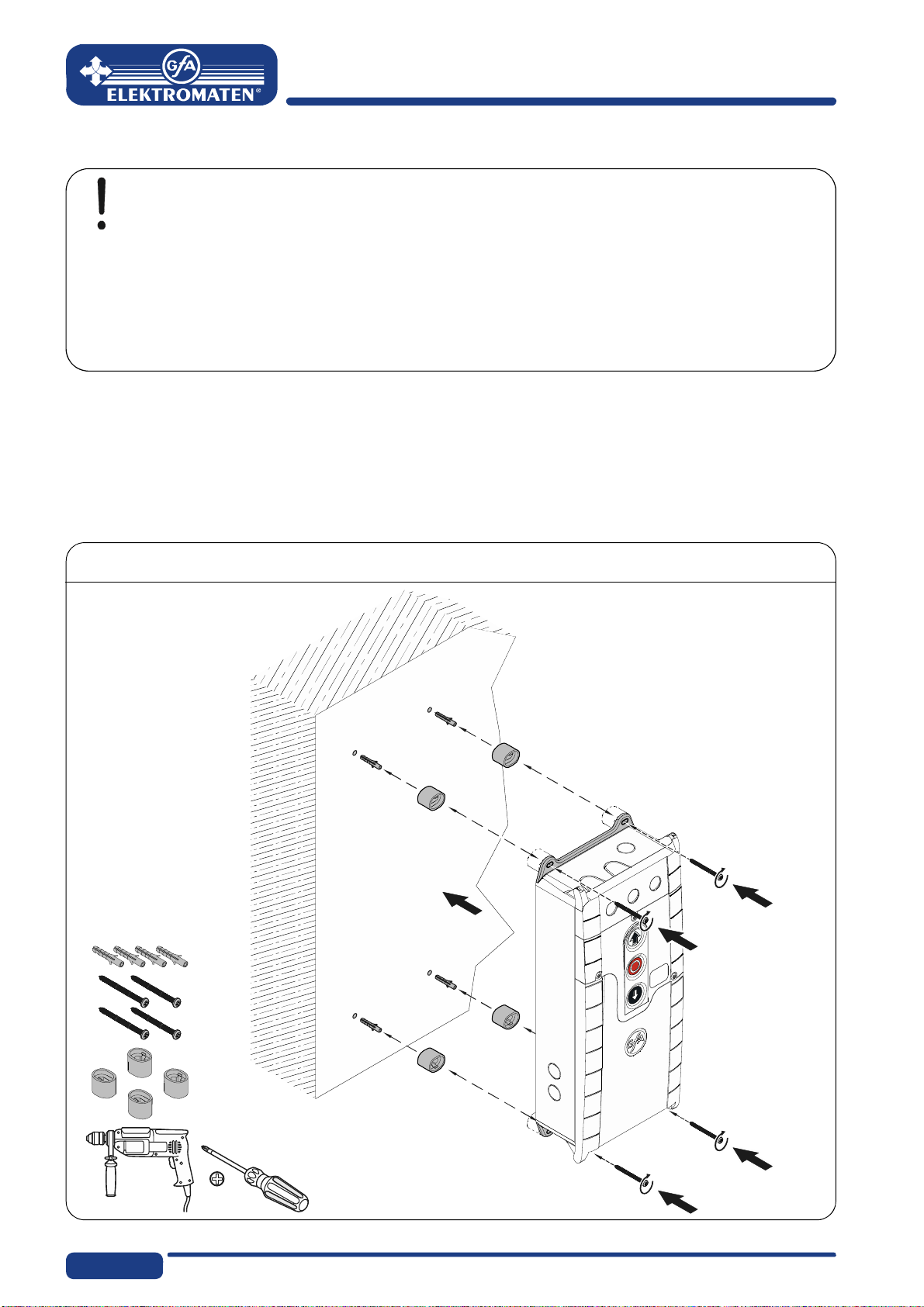
3Mechanical installation
Control installation!
Indoor use only
Mount on a level ground free of vibration
Only mount in the vertical position
Door must be in clear view from place of assembly
Requirements
The permissible loads on walls, mountings, connection and transmission elements must not
be exceeded.
Mounting
The control is mounted via 4 elongated holes
9
4Electrical installation
Warning - Danger to life from electric shock!
Disconnect the cables (mains OFF) and check that the supply is off
Observe the applicable regulations and standards
Ensure proper electrical connection
Use suitable tools
On-site backup fuse and disconnector unit!
Only use current sensitive earth leakage circuit breakers type B for FI-drive units
Connection to the indoor installation via an all-pole disconnector unit, with current
≥ 10 A as per EN 12453 (e.g. CEE plug connector, main switch)
Read the drive unit installation instructions!
10
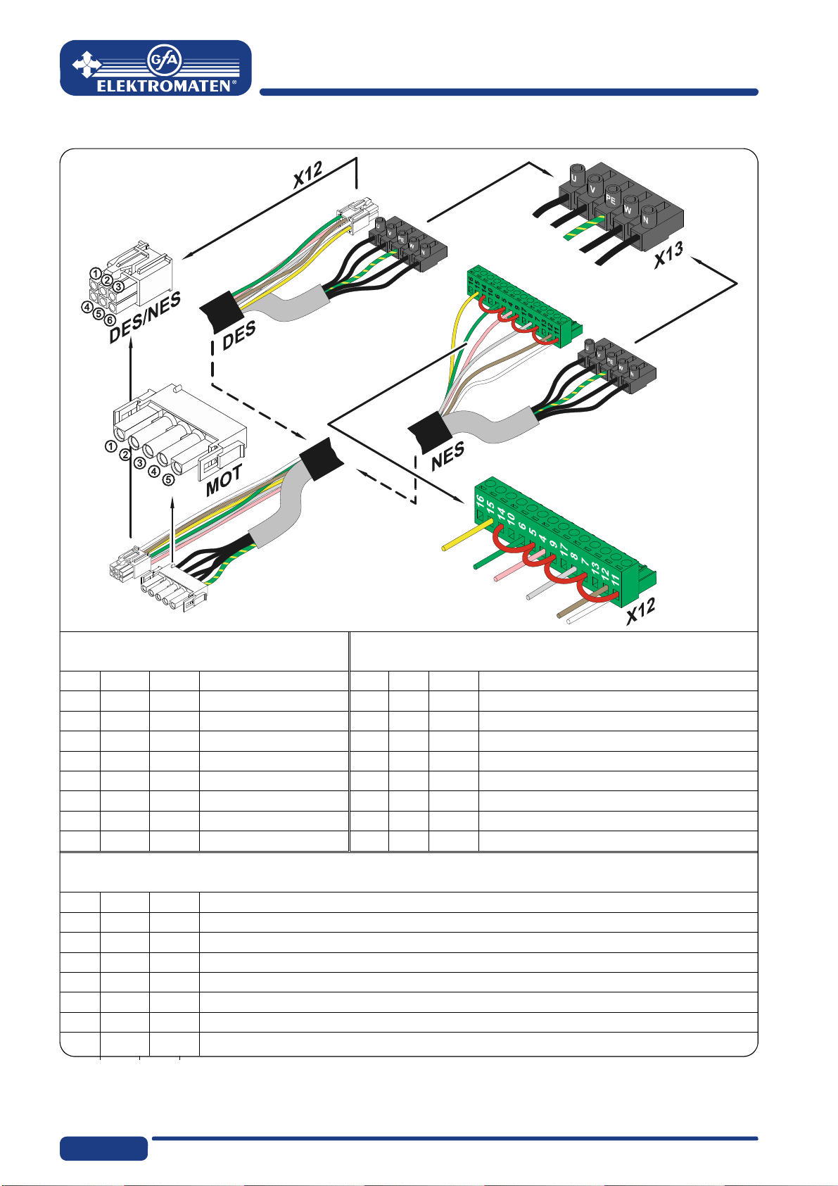
Connection cable connection overview
DES and NES
Motor connection cable
DES
Connection cable limit switch
MOT X13 Motor plug DES X12 Limit switch plug
Pin Core Term. Pin Core Term.
1 3 W Phase W 15/wh 1+24 V safety circuit
2 2 V Phase V 26/bn 2Channel B (RS485)
3 1 U Phase U 37/gn 3Ground
4 4 N Neutral conductor (N) 48/ye 4Channel A (RS485)
5 PE PE 59/gy 5Safety circuit
610/pk 68 V DC supply voltage
NES
Connection cable
NES X12 Limit switch plug
Pin Core Term.
1 5/wh 11 Limit switch common +24 V, wire link on X12 5, 7, 9, 11, 14
2 6/bn 12 S5 Additional limit switch, testing or safety edge function
3 7/gn 6 S3 Open limit switch
4 8/ye 15 S6 Additional limit switch, relay function or intermediate open
5 9/gy 8 S4 Closed limit switch
6 10/pk 4 Safety circuit

11
Limit switch assignment for screwable version until year of manufacture of 1997
F1 Thermal contact X12 Limit switch board
G1 Rectifier S1 Emergency open limit switch
M1 Motor S2 Emergency close limit switch
S10 Emergency manual operation S3 Open limit switch
W1 Connection cable S4 Close limit switch
Y1 Spring-loaded brake S5
A
uxiliary limit switch
S6
A
uxiliary limit switch
Assignment of individual limit switches
A
1 Terminal box S3 Open limit switch
F1 Thermal contact S4 Close limit switch
M1 Motor S5
A
uxiliary limit switch
S10 Emergency manual operation S6
A
uxiliary limit switch
W1 Connection cable
56710 93214(N)
S6 S5 S3 S1 S2 S4
S10 F1
G1
Y1
1
3
2
4
5
X12
W1
M1
5 671093214PE
M1 S10 F1S4S3 S5 S6
W1
A1
12
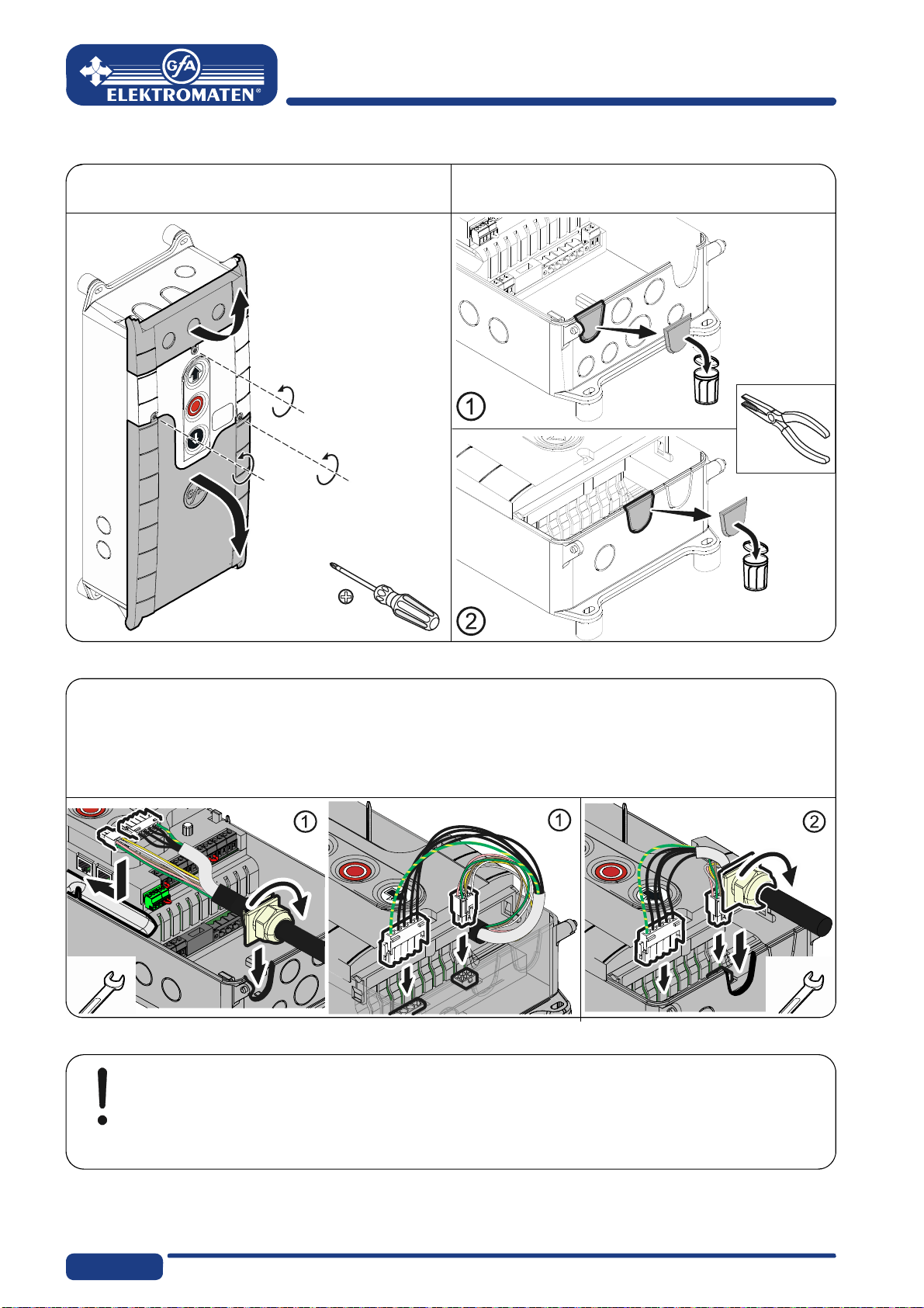
Carrying out the electrical installation
▶ Remove covers. ▶ Open cable entry ① or ②.
▶ Insert and connect connection cable in the open cable entry ① (from below) or ② (from
above).
▶ Properly tighten cable glands.
Caution - Damage of components!
Open cable entry with suitable tool
Install cable entries and/or cable glands
13
Mains connection
3~, N, PE
190 – 440 V
50 -60 Hz
3~, PE
190 – 440 V
50 -60 Hz
1~, N, PE, sym.
190 – 230 V
50 -60 Hz
1~, N, PE, asym.
190 – 230 V
50 -60 Hz
3 x 400V 1 x 230V / 3 x 230V
Mains connection to control
Completing the electrical installation
Connect any other control devices and/or safety devices.
Install and tighten cable entries and/or cable glands.
For initial operation, leave the control covers open.
L1L2L3 NPE
L1 L2L3 PE
LNPE
SI 25.15WS, SI 45.7WS
LNPE
SI 25.15WS, SI 45.7WS
20.1
1.5
1.8
1.9
20.2
1.6
20.3
1.7
230V
400V
20.1
1.5
1.8
1.9
20.2
1.6
20.3
1.7
230V
400V
3
14
Overview of control
DES/
NES DES or NES limit switch socket X24 V mains supply, external devices
X1 Mains supply
F1 Micro-fuse 1.6 A time lag X2 Safety edge system and
Door safety switch
MOT Motor socket
S Selector switch X3 Emergency stop button
S11 Open push-button X4
A
utomatic closing On/Off
S12 Stop button X5 Control device, external three push-button
S13 Close push-button X6 Through photo cell, reflective photo cell
UBS Universal command sensor socket X7 Pull switch
V1 Display X8 Intermediate open On/Off
X20 Potential-free relay contact 1
20.1
1.5
1.8
1.9
20.2
1.6
20.3
1.7
F1 = 1,6A t
230V
400V
2.1
2.3
2.5
2.2
2.4
V1
MOT
DES/
NES S11
S12
S13
X20
X3
X2
X4 X5 XX6 X7 X8
F1
UBS S
X1
970

15
5Starting up the control
▶ Plug in or switch on
the mains supply line
DES: Rapid adjustment of final limit positions
1. Check rotating direction
2. Move to open final limit position 3. Save open final limit position
4. Move to close final limit position 5. Save close final limit position
Note!
Rapid adjustment is complete, "Hold-to-run" door operating mode is active
Change of OPEN/CLOSE final limit positions via menu items "1.1" to "1.4"
Pre-limit safety edge adjusts automatically
Changing the pre-limit position is possible via menu item "1.5"

16
Read the drive unit installation instructions!
For adjusting the mechanical limit switch, see the drive unit installation
instructions
NES: Rapid adjustment of final limit positions
1. Check rotating direction
2. Move to open final limit position and adjust S3 OPEN limit switch
3. Move to close position 5cm above the ground and adjust S5 pre-limit switch
4. Move to close final limit position and adjust S4 CLOSE limit switch

17
6Electrical installation – control accessories
X1 Ex ter nal su pply
X3 Emergency st op
X4 Aut omatic closi ng On /Off
X1 External supply X3 Emergency stop X4 Automatic closing On/Off
A
1 External device
A
2 Control device
A
3Control device
Emergency stop Key-switch
X5 Contr ol d evice
X5 Control device
A
4 Key-switch
A
6Three push-button
X6 Pho to cell
X6 Photo cell
A
8 Reflective
photo cell
Through
photo cell
Through
photo cell
A9 Transmitter A11 Transmitter
A10 Receiver A12 Receiver
X1
A1
X3
A2
2
1
S15
X4
A3
12
4
3
S17
X5
P
1
S17
2
A4
X5
3
2
1
S14
4
3
2
1
S16
2
1
S15
A6 X5
12345
24V
X6
A8
X6
12
24V
A9
12345
24V
A10
X6
12
24V
A11
12 3
24V
A12
PNP

18
X6 Ligh t curtai n
X6 Light curtain
X20 Function relay Light curtain Light curtain
Test light curtain A25 Transmitter A27 Transmitter
A26 Receiver A28 Receiver
X7 Radi o rec eiver
X7 Pull switch
X8 Inter medi ate sto p
X7 Radio receiver X7 Pull switch X8 Intermediate stop
X20 Tr af fic li ght
X20 M agnetic brake
X20 Traffic light X20 Magnetic brake
H1 Traffic light G1 Rectifier
Y1 Magnetic brake
X20
20.1
20.2
20.3
24V
24V*
X6
12
24V
A25
12345
24V
A26
24V
24V*
PNP
X6
12
24V
A27
12 3
24V
A28
24V
24V*
1234
24V
X7
A13
A14
4
3
X7
S19
A15
12
4
3
S17
X8
X20
20.1
20.2
20.3
H1
1.9
1.8
20.1
20.2
20.3
1.9
1.8
21.1
21.2
21.3
X20/ Y1
G1
C1

19
Spiral c abl e conn ection
Spiral cable connection
Electrical safety edge system
A18 Junction box
ST+ Voltage supply
ST Door safety switch input
SK1 Electrical safety edge system input
SK2
B1 Electrical safety edge system
R1 End of line resistor 8k2
X2 Door control socket
Pneumatic safety edge system
A18 Junction box
ST+ Voltage supply
ST Door safety switch input
SK1 Pneumatic safety edge system input
SK2
DW Pneumatic switch
R2 Series resistor 1k2 testing
X2 Door control socket
Optical safety edge system
A19 Junction box
ST+ Voltage supply
ST Door safety switch input
SK/b Mains supply (brown)
SK/g Output (green)
SK/w Ground (white)
B2 Optical transmitter
B3 Optical receiver
X2 Door control socket
Door safety switch
A18 Junction box
A
19
A20 Junction box switch
S30 Pass-door switch
(NC)
S31 Slack-rope switch
(NC)
Door safety switch, crash switch
A18 Junction box
A
19
A21 Junction box switch
S38 Crash switch
(NC)
A22 Junction box switch
S39 Crash switch
(NO)
234
2.1
2.3
2.5
2.2
2.4
X2
1
2
3
4
ST+
ST
SK1
SK2
A18 B1
8K2
R1
234
2.1
2.3
2.5
2.2
2.4
X2
1
2
3
4
ST+
ST
SK1
SK2
A18 DW
1K2
R2
234
2.1
2.3
2.5
2.2
2.4
X2
1
2
3
4
ST+
ST
SK/b
SK/g
SK/w
A19
br
gn
w
B3
B2
ST
A18/A19
A20
2
1
S30/
S31
ST
A18/A19
A21
2
1
S38
ST
A18/A19
A22
2
1
S39

20
Note!
Use of a safety edge system only possible via menu "0.1",
door operating mode "3", "4" or "6"
Completing the electrical installation
If required, connect other electrical equipment and/or safety devices, install cable entries
and/or cable glands.
Table of contents
Other Elektromaten Door Opening System manuals

Popular Door Opening System manuals by other brands


Synergy Hardware
Synergy Hardware S900 Series Fixing instructions

Dorex
Dorex 441C Series installation instructions

Allegion
Allegion Von Duprin 98 Series installation instructions

GEZE
GEZE Powerdrive PL-HT Pre-installation instructions

Norton
Norton 1600 Series installation instructions

Dorma
Dorma 96 GSR-EMF Mounting instructions

Kesseböhmer
Kesseböhmer eTouch DISPENSA operating instructions

ECO Schulte
ECO Schulte FH842 Assembly instructions

Dormakaba
Dormakaba RTS88 installation instructions

LCN
LCN 4050AT installation instructions

Tormax
Tormax iMotion 1301 Instructions for use

Von Duprin
Von Duprin 98/9927 installation instructions