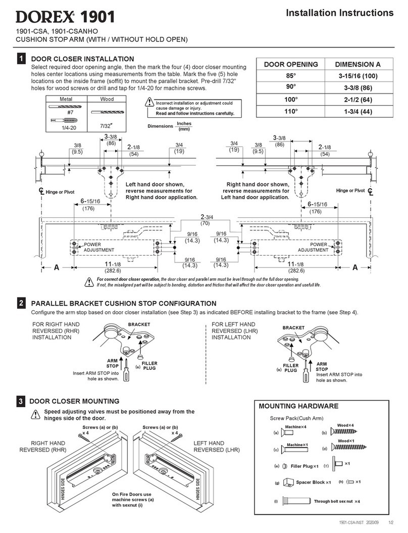
INTERCHANGEABLE DOOR HANDING
WRENCH
FOREARM
STUD
30°
APPROX
30°
PRELOAD
MAIN ARM
HOLD OPEN CONTROL
FOR 441H ONLY
SHAFT
SCREW
CLOSING SPEED
VALVE
LATCHING
SPEED
VALVE
BACKCHECK
VALVE
INSERT
COVER
INSTALLATION SEQUENCE
LEFT HAND DOOR SHOWN - RIGHT HAND DOOR IS OPPOSITE
IMPROPER INSTALLATION OR REGULATION
MAY RESULT IN PERSONAL INJURY OR
PROPERTY DAMAGE. FOLLOW ALL
INSTRUCTIONS CAREFULLY.
CAUTION
441C/441H/441S Series
BRACKET
FILLER PLUG
For Heavy Duty Arm w/ STOP (441C), w/ STOP and Hold Open (441H), w/ Spring Stop (441S)
SPRING STOP
FOR 441S
DEAD-STOP
FOR 441C
AND 441H
Left Hand Right Hand
DOOR HANDING
Outside
(Pull Side)
Outside
(Pull Side)
Inside
(Push Side)
Inside
(Push Side)
GENERAL NOTES
1. Door must be hung on ball bearing or anti-friction hinges.
2. Door and frame must be properly reinforced at the door closer and arm mounting areas.
3. For non-labelled wood doors pre-drill and use wood screws.
4. For steel reinforced hollow metal doors, drill and tap for the appropriate machine screws.
5. For non-reinforced hollow metal doors and labeled wood doors, drill and use sex-nut bolts.
6. For steel frames drill and tap for the appropriate machine screws.
7. For optional drop plates installation see separate installation instructions.
8. Door closer should not be installed on an exterior side of a door or door frame surface.
9. Hold open arms should NOT be installed on fire doors
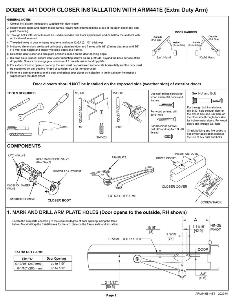
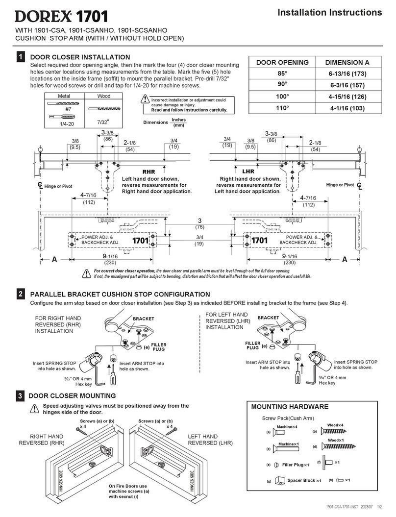
1. Determine door handing (refer above) and position door closer with spring tube end located away from
the hinges centerline.
2. Before installing the door holder ensure that the backcheck is not engaged. Turn backcheck
valve-screw counter-clockwise. Also, ensure that the valve at the back of the door closer is completely
screwed-in.
3. Select the desired degree of opening as indicated on page 2 and use the appropriate position of door
closer and parallel arm bracket with respect to the hinge centerline. Mark the parallel arm bracket
mounting holes on the frame door stop soffit using the actual parallel bracket at the selected location
(as illustrated on page 2).
4. Mark the door closer mounting holes on the door at selected location.
a. For prepped (reinforced) hollow metal doors, drill and tap for ¼-20 UNC and attach door closer to
door using provided machine screws.
b. For non-prepped hollow metal fire rated doors: drill 3/8” (9.5 mm) holes on exterior door surface and
5/16“ (8 mm) hole on door interior surface and attach door closer to door using through bolt sexnuts
and machine screws. (Not supplied)
5. For non-rated wood doors pre-drill 3/16” (4.8 mm) and use wood screws. For fire rated wood doors drill
3/8” (9.5 mm) holes through door and attach door closer to door using through bolt sexnuts and
machine screws. (Not supplied)
6. Using a wrench on the door closer bottom shaft (refer to illustration below), turn the shaft towards the
hinge about 30° (for pre-loading) and place main arm on the closer’s top shaft. Insert the main arm
screw into the top shaft and tighten.
7. Temporarily remove the arm stop from the parallel bracket and disengage the Hold-Open function with
the Hold-Open control handle (if arm with Hold-Open function is used).
8. Rotate the arm on the closer shaft so that the main arm is approximately parallel to the door and
ensuring that the arm elbow clears the door surface by about 1/2” to 1” (13mm to 25mm). Verify that
the parallel arm bracket holes line-up with the marked-up holes. Once the position of the holes has
been verified, remove the arm with bracket and proceed in preparing the mounting holes as instructed
in note 9.
9. For prepped frames or metal frames, drill and tap for ¼-20 UNC and use provided machine screws.
For non-prepped frames or wood frames, pre-drill and install provided #14 wood screws.
10. To provide additional stiffness to the parallel bracket mounting, install an additional mounting screw on
the parallel bracket using the spacer block between the door frame jamb ceiling face and the parallel
bracket.
11. Install the arm solid stop or the spring stop on the parallel arm bracket and verify that the door opens
to the approximate desired opening angle. Install supplied filler plug on the unused stop position hole.
12. Door Closer Control Adjustment:
a. Adjust the closer closing speeds using the closer regulating valves as required. Turn valves
clockwise for a slower closing speed and counter-clockwise for a faster closing speed. A normal
closing time from 90° open position to door stop positions is 5-7 seconds, evenly divided between
door closing moving speed and latch speed.
b. Adjust spring power if required, depending on door size and weight.
c. Adjust the backcheck to slow down the door before the dead-stop. Note that the backcheck is used
only to provide damping and prevent the door from opening too fast. Does not replace door stop.
d. For arms with Hold-Open function, engage the spring loaded detente by turning the control handle
90° as shown.
13. To install the door closer cover, first place insert in the appropriate cutout, place shaft insert over the
lower shaft, then install cover and secure with supplied mounting screws.
5/32” OR 4 mm
Allen key
441C/441H/441S-INST 2022-04
PAGE 1
SPRING TUBE
SCREW
