25.07.2014 ZUG ELEKTROMET
3. Heater Installation
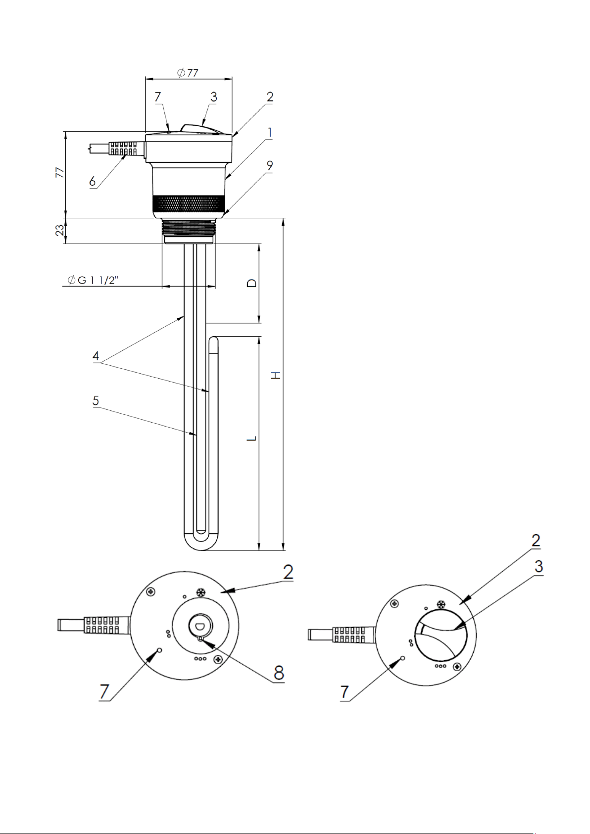
3.1 Assembly in tank
A. Type of tank
he tank and its connections must be made of metal. The structure of the heater provides
a protective circuit connecting protective conductor of the power cord with a metal head. This
connection is made in a sustainable way inside the body of the heater.
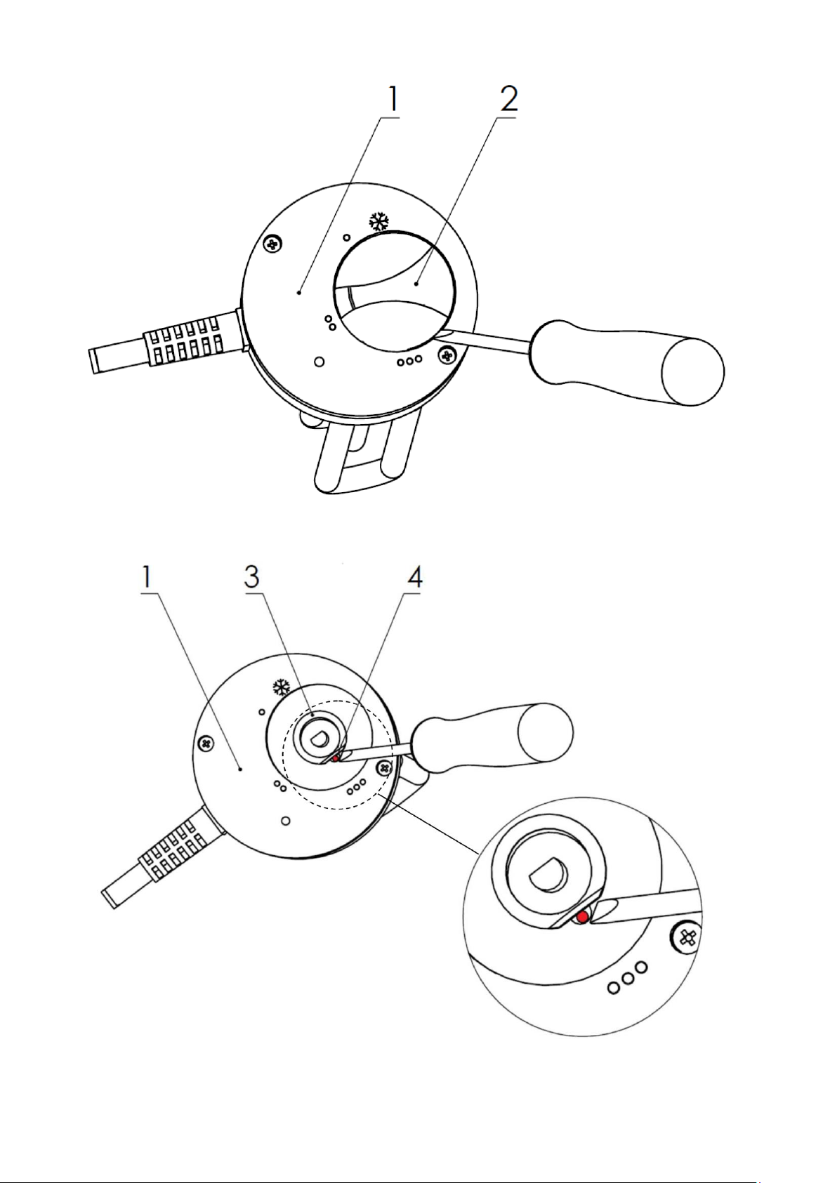
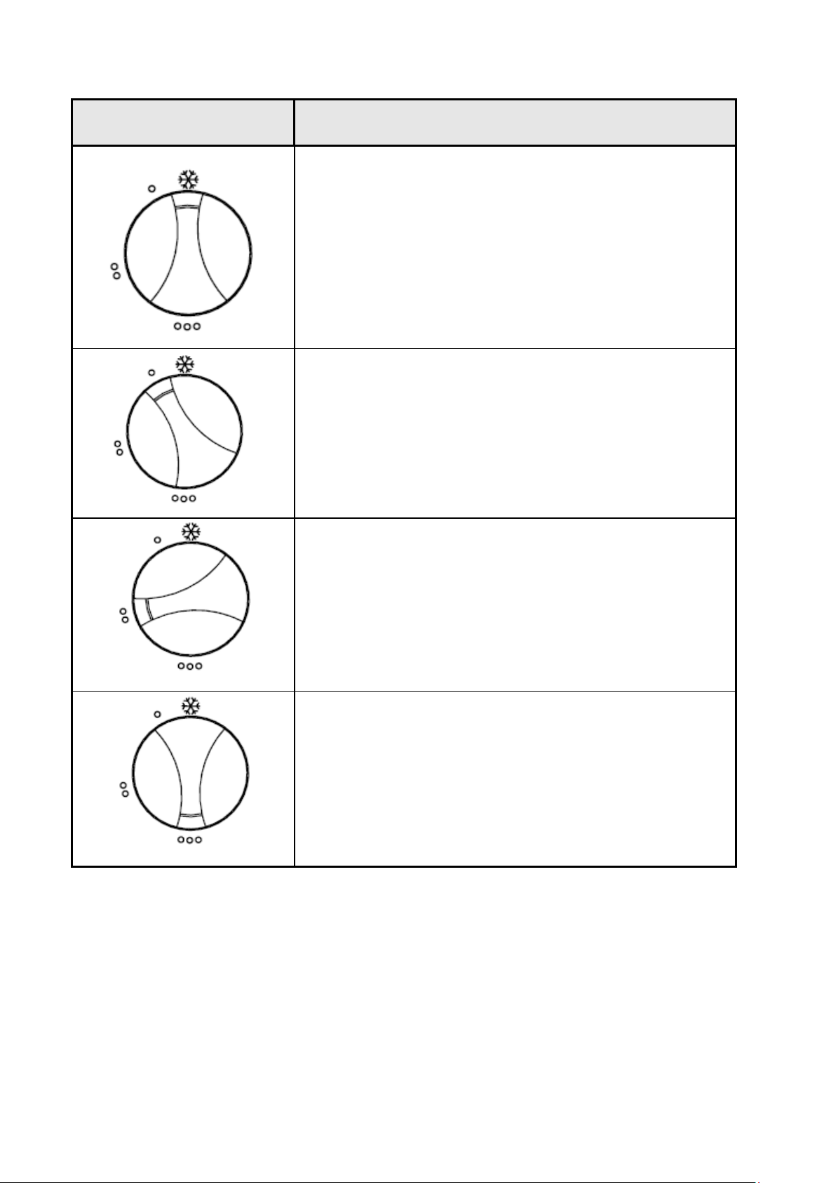
B. Working position
The heater may only operate in horizontal or semi horizontal position.
During operation heating element and the sensor protection must be totally immersed in
water and free thermally forced water circulation must be ensured. The length of the coupling
for assembling the heater shall not exceed circa 70 mm so that it does not stand out from the
heating elements dead zone (unheated zone). Heater casing must not be covered nor thermally
insulated as it would disturb normal operation of the temperature controller and of the
temperature limiter installed in the casing. When assembling the heater make sure that heating
elements length fits into the tank and that they do not touch any internal parts of the tank, such
as heat exchangers or thermometric pipes.
C. Pressure tanks
The heater is adapted for installation in pressure tanks of an admissible pressure not
higher than 10 bar. All the assembly, installation and service conditions for these tanks (boilers)
must be observed. It is also absolutely obligatory to install a safety valve with the opening
pressure not higher than indicated in the tank operating parameters. Valve flow capacity should
be chosen taking into account the power of all heaters and heat exchangers which heat water in
tank, as regulated by the Office of Technical Inspection, using the technical data published by
particular safety valves manufacturers.
Safety valve opening pressure when heater type EJK mini is used must not exceed 10 bar.
When installing an electric heater in a pressure tank it must be also remembered that the
operation of these devices is subject to various kinds of technical inspection, particularly in
accordance with the Regulation of the Minister of Economy, Labour and Social Policy dated
9.07.2003. Among other things, it stipulates that:
1. 1. Electric storage water heaters for domestic water of working temperature not higher
than 100ºC and capacity not larger than 300 l as well as tanks filled with water (heat exchangers
included) of working temperature not higher than 100ºC and capacity not larger than 500 l are
subject to simplified inspection, and therefore do not need to be reported to the Office of
Technical Inspection.
2. Electric water heaters of capacity larger than 300 l as well as tanks filled with water
(heat exchangers included) of capacity larger than 500 l are subject to limited inspection and
need to be reported to the Office of Technical Inspection.