Sure Flame S1505B User manual

PRODUCTS
S1505B
CONSTRUCTION HEATER
Rev. 4.32 Aug 29, 2014
SERVICE AND MAINTENANCE MANUAL No. 974-9308
PLEASE RETAIN FOR FUTURE REFERENCE
A DIVISION OF HAUL-ALL EQUIPMENT LTD.
4115 - 18 Ave. N, Lethbridge, Alberta
www.sureflame.com
Page 2 S1505B Manual 974-9308 Rev. 4.32; Aug 29 2014
S1505B Construction Heater
Failure to comply with the precautions and instructions
provided with this heater, can result in death, serious
bodily injury and property loss or damage from hazards
of fire, explosion, burn, asphyxiation, carbon monoxide
poisoning, and/or electrical shock.
Only persons who can understand and follow the
instructions should use or service this heater.
If you need assistance or heater information such as
an instruction manual, labels, etc. Contact the
manufacturer.
Fire, burn, inhalation, and explosion hazard. Keep solid
combustibles, such as building materials, paper or
cardboard, a safe distance away from the heater as
recommended by the instructions. Never use the heater
in spaces which do or may contain volatile or airborne
combustibles, or products such as gasoline, solvents,
paint thinner, dust particles or unknown chemicals.
Not for home or recreational vehicle use
WARNING
WARNING
GENERAL HAZARD WARNING

S1505B Manual 974-9308 Rev. 4.32; Aug 29 2014 Page 3
READ THIS
WARNING
FIRST!
The heater is designed and approved for use as a construction
heater under ANSI Z83.7-2000. The primary purpose of con-
struction heaters is to provide temporary heating of buildings
under construction, alteration, or repair and to provide tempo-
rary emergency heat. Properly used the heater provides safe
economical heating. Products of combustion are vented into
the area being heated.
The heater is not designed as an Unvented Gas Fired Room
Heater under ANSI-Z21.11.2 and should not be used in the
home.
ANSI A119.2(NFPA 501C)-1987 Recreational Vehicle Stand-
ard prohibits the installation or storage of LP-Gas containers
even temporarily inside any recreational vehicle. The standard
also prohibits the use of Unvented Heaters in such vehicles.
NFPA-58 1989 STANDARD FOR THE STORAGE
AND
HANDLING OF LIQUEFIED PETROLEUM GASES
Use of the heater must be in accordance with this Standard and
in compliance with all governing state and local codes. Storage
and handling of propane gas and propane cylinders must be in
accordance with NFPA 58 and all local governing codes.
We cannot anticipate every use which may be made for our
heaters. CHECK WITH YOUR LOCAL FIRE SAFETY AU-
THORITY IF YOU HAVE QUESTIONS ABOUT LOCAL REGU-
LATIONS.
Other standards govern the use of fuel gases and heat produc-
ing products in specific applications. Your local authority can
advise you about these.

Page 4 S1505B Manual 974-9308 Rev. 4.32; Aug 29 2014
FOR YOUR SAFETY
DO NOT USE THIS HEATER IN A SPACE WHERE
GASOLINE OR OTHER LIQUIDS HAVING
FLAMMABLE VAPOURS ARE STORED OR USED.
S1505B
CONSTRUCTION HEATER
Contents:
Page
Specifications 5
Installation 6
Installation Using a Propane Supply Cylinder 7
Installation for Natural Gas Applications 7
Operating Instructions 8
Common Installation and Operational Problems 9
Safety Controls 9
Safety Features 10
On-Site Hazards 10
Preventative Maintenance 11
Troubleshooting Tables 12
Replacement Parts 20
Wiring Diagrams 22
Two Stage Thermostat Wiring Diagram 24
LPG - Propane Fuel Vaporization Rate 25
Maximum BTU Content (Propane) 25
Pressure & Flow Equivalents 25

S1505B Manual 974-9308 Rev. 4.32; Aug 29 2014 Page 5
Specifications
AGA certified to ANSI Z83.7-2000 Construction Heater
Gases: Natural or Propane
Capacity: 1,500,000 Btu/h maximum
850,000 Btu/h minimum
Orifice Size: 41 DMS (X46)
Blower: 7,000 cfm
Electrical Rating: 115 volts, 60 Hz, 9.4 amps, Single Phase
Min. Temperature Rating: Minus 40 degrees F
Gas Supply:
Inlet Pressure Manifold Pressure
Max W.C. Min W.C. Max W.C. Min.W.C.
Propane 14" 9" 2.7" 0.75"
Natural 14" 9" 7.2" 2.0"
(Minimum inlet pressure is for purpose of input adjustment)

Page 6 S1505B Manual 974-9308 Rev. 4.32; Aug 29 2014
Installation
The Sure Flame Model S1505B is a direct fired gas heater intended to be
used primarily for the temporary heating of buildings under construction,
alteration, or repair. Since all the products of combustion are released into
the area being heated, it is imperative that adequate ventilation is provided.
The flow of supply air and combustion gases must not be obstructed in any
way. Do not use the heater with ductwork as this will restrict the flow of supply
air.
1 Install the heater in a horizontal position at least 6 ft. (1.83 m) from any
LP-gas container, and allow the following clearances from any combus-
tible materials:
Front Outlet: 20 feet Sides: 2 feet
Intake: 2 feet Top: 4 feet
Front Outlet must not be directed at any LP-gas container within 20 feet.
Also make sure that no flammable vapours are present in the space
where the heater is being used.
2 When connecting the heater to a natural gas or propane supply line
ensure that the pressure at the heater inlet is within the specified range.
Please refer to Propane and Natural Gas Installation sections in this
manual. Excessive pressure (over 1/2 psig) will damage the controls
and void the warranty.
3 Visually inspect the hose assembly and ensure that it is protected from
traffic, building materials, and contact with hot surfaces. If it is evident
that there is excessive abrasion or wear, or the hose is cut, it must be
replaced.
4 After installation, check the hose assembly for gas leaks by applying a
water and soap solution to each connection.
5 Connect the heater to an adequate 115 volt electrical supply and in
compliance with the National Electrical Code, ANSI/NFPA 70. For
protection against shock hazard the supply cord should be plugged
directly into a properly grounded three-prong receptacle.
6 In all applications install the heater in such a manner that it is not directly
exposed to water, spray, rain and/or dripping water.

S1505B Manual 974-9308 Rev. 4.32; Aug 29 2014 Page 7
Installation Using A
Propane Supply Cylinder
1 When installing the heater for use with propane gas, set the gas selector
valve to “Propane” and lock in position.
2 The supply container MUST be equipped with an LP Gas Regulator that
complies with ANSI/UL 144 Standard for Pressure Regulating Valves for
LP-Gas. Another regulator must be installed in the heater to reduce the
pressure from this regulator down to a maximum inlet pressure of 1/2 psi.
3 Arrange the cylinder supply system to provide for vapour withdrawal from
the operating cylinder. Supplying liquid propane to the heater is
dangerous and will damage the components.
4 Ensure that for the surrounding temperature the size and capacity of the
propane supply cylinder is adequate to provide the rated Btu/h input to
the heater.
5 Turn off the propane supply valve at the cylinder when the heater is not
in use.
6 The installation must conform with all local codes, or in the absence of
local codes, with the Standard for the Storage and Handling of Liquedied
Petroleum Gases, ANSI/NFPA 58.
7 When the heater is to be stored indoors, the propane cylinder(s) must be
disconnected from the heater and the propane cylinder(s) removed from
the heater and stored in accordance with the National Standard for the
Storage and Handling of Liquedied Petroleum Gases, ANSI/NFPA 58.
Installation For
Natural Gas Applications
1 When installing the heater for use with natural gas, set the GAS
SELECTOR VALVE to the ”Natural” position.
2 A regulator must be installed on the heater to ensure that the pressure
to the heater does not exceed 1/2 psi inlet pressure.
3 The installation of this heater to a natural gas supply must conform with
all applicable local codes or, in the absence of local codes, with the
National Fuel Gas Code ANSI Z223.1/NFPA 54.

Page 8 S1505B Manual 974-9308 Rev. 4.32; Aug 29 2014
Operating Instructions
1. Set GAS SELECTOR VALVE to gas being used. The conversion shall
be done by the owner or lessor of the equipment.
Warning: When using propane gas, the GAS SELECTOR VALVE must
be locked in position.
2. Ensure FIRING VALVE is in the “ON” position.
3. Connect power cord to a 115 volt supply.
4. Open gas supply.
5. Set thermostat to the desired temperature.
6. Push START button. After a short delay, the heater will start.
Note: Heater will cycle between high flame, low flame, and off as
required.
7. To stop: push STOP button. If heater is to remain off, disconnect power,
and close gas supply.
The appliance area should be kept clear and free from combustible materi-
als, gasoline, and other flammable vapours and liquids.
Ensure that the flow of supply air and combustion gases is not obstructed.
The installation and operation of the heater shall comply with the code
requirements specified by the authorities having jurisdiction.
General criteria for the use of construction heaters may be found in the
applicable sections of American National Standard A10.10-1987, Safety
Requirements for Temporary and Portable Space Heating Devices and
Equipment Used in the Construction Industry.
THE INSTALLATION AND MAINTENANCE OF THE
HEATER MUST BE ACCOMPLISHED BY A QUALIFIED
SERVICE PERSON.

S1505B Manual 974-9308 Rev. 4.32; Aug 29 2014 Page 9
Common Installation And
Operational Problems
1 LOW VOLTAGE
This is one of the most common problems and is usually the result of the
supply cord having too small of a wire gauge for its length. Low voltage
results in the motor overheating, burnt relay contacts, or a relay that will
not make contact.
2 SUPPLY LINE TOO SMALL
3 INSUFFICIENT VAPORIZATION AT SUPPLY
Normally caused by too small size of supply tank.
4 IMPROPER GAS SUPPLY PRESSURE
Usually a result of supply pressure being too high because of improper
or lack of regulation.
5 DIRTY GAS SUPPLY
Dirty gas can cause strainers to plug or form a build-up in the burner
orifice.
6 LACK OF PREVENTATIVE MAINTENANCE
Heaters must be cleaned as required, especially when used in a dirty
environment.
7 IMPROPER SUPPLY OF FRESH AIR
It is normally recommended that the intake air of the heater be taken from
outside the enclosed area. This provides a slight pressurization and
prevents any problems associated with recirculation.
Safety Controls
Servicing of Sure Flame Construction Heaters normally involves one of
several built-in safety features. The Model S1505B incorporates devices to
detect the following:
1 LOSS OF FLAME Gas supply is shut off if flame is lost to
prevent raw gas from leaving the heater.
2 OVERHEATING (a) Thermal overload protection in the mo-
tor.
(b) High temperature limit switch in the
combustion chamber.
3 LOSS OF POWER Total shutdown with manual reset required.
Any one of the safety devices will create a
loss of power situation.
4 BLOCKED AIR SUPPLY A switch detects the differential pressure in
the combustion chamber and shuts down
when insufficient .
5 LOW INLET PRESSURE A pressure switch monitors the gas inlet and
closes the safety shut-off valve if pressure
drops below the preset limit.

Page 10 S1505B Manual 974-9308 Rev. 4.32; Aug 29 2014
Safety Features:
1 LOCKING POSITION FOR LPG ON GAS SELECTOR LEVER
Units used with LPG while the gas selector valve is positioned for Natural
Gas will produce significantly more heat than the rated Btu/h. This is
definitely a safety hazard.
2 LOW SKIN TEMPERATURE
Sure Flame Heaters are designed to have a low skin temperature. This
provides added safety in the workplace.
3 DURABLE CONSTRUCTION
The Model S1505B uses a stainless steel burner for long life and
consistent performance.
In order to maintain the highly efficient combustion of the Sure Flame
Heater, the combustion chamber must remain as manufactured. Any
change or distortion could alter the fuel/air mixture and create hazardous
gases.
On-Site Hazards
1 SHORTING OUT OF DEFECTIVE COMPONENTS
This is a very common problem which saves short term expense at the
risk of a large future cost. Any heaters found in this condition should be
removed immediately.
2 IMPROPER ENCLOSURES
When heaters are installed partially to the outside for fresh air intake,
strict adherence must be made to the minimum clearance to combustibles
given on the instruction plate. Wood framing around a heater is a hazard
and should not be used.
3 SUPPLYING LIQUID PROPANE TO HEATER
This problem has occurred from time to time. To minimize the damage,
shut off the gas supply and let the heater run until all of the liquid in the
lines has been burnt.

S1505B Manual 974-9308 Rev. 4.32; Aug 29 2014 Page 11
Preventive Maintenance
Sure Flame Construction Heaters are built to withstand the rigours of
operating on construction sites, mining applications, and a multitude of other
locations where heaters are used. To maintain the reliable performance it
is necessary to perform regular maintenance.
A VISUAL CHECKS
The following items should be checked for excessive wear or damage:
1) Wheels
2) Cords and Connectors
3) Wiring and Conduit
4) Heater Shell (including heat shield) and Control Box
B BURNER
Flame Rod and Insulator - Clean with soap and water or solvent on a
routine basis. Any build up on burner should
also be removed at this time.
Ground Wire - Ensure that the ground wire is secured to
the burner. This is necessary for the flame
detection system to operate.
Spark Plug - Clean with solvent and check spark gap.
C FLAME SAFEGUARD CONTROL
The Fenwall Control can be cleaned using compressed air or alcohol. Do
not use any other liquid or aerosol spray cleaners.
In areas of high humidity, the control should be removed and placed in
a dry atmosphere when the heater is expected to be out of service for an
extended time.
It is recommended that units purchased as spares be rotated periodi-
cally, so that each unit will be placed in operation at least once every 90
days.
D MOTOR - Motors equipped with oil cups should require only a few drops
of clean, light machine oil every year. Motors not equipped with oil cups
are fitted with sealed bearings and no oiling is required.
E FAN - Check for dust or dirt build up on fan blades. Check the tightness
of the set screw and run the heater to check for fan vibration.

Page 12 S1505B Manual 974-9308 Rev. 4.32; Aug 29 2014
Troubleshooting
The troubleshooting section has been divided in to six tables. Choose
the appropriate table from the list below:
Chart A – Heater does not start, fan does not start
Chart B – Heater does not start, fan starts, no spark, no flame
Chart C – Heater does not start, fan starts, spark, no flame
Chart D – Heater starts, flame lights but goes out after a few
seconds
Chart E – Heater starts, but fails during operation
Chart F – Other problems

S1505B Manual 974-9308 Rev. 4.32; Aug 29 2014 Page 13
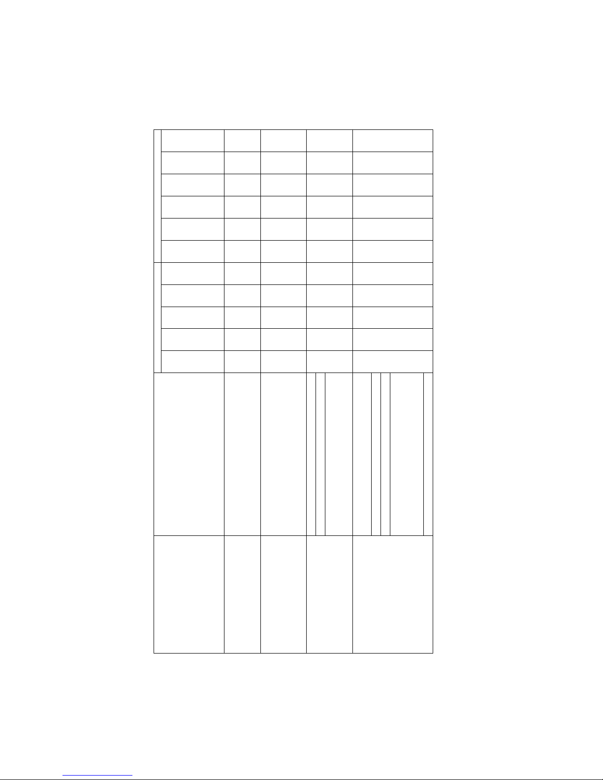
Chart A – Heater does not start, fan does not start
Indicators Outside Control Box Indicators Inside Control Box
Symptom Possible Causes
Green Start Switch
Red Stop Switch
Thermostat Power
Light
Thermostat Stage
1 Light
Thermostat Stage
2 Light
L2
L6
L7
L8
L12
Flame Control
LED
No electrical supply off off off off off off off off off off off
Stop switch fails open
Green start light does not
come on when start switch is
pressed. Start switch fails open
off off off off off on off off off off off
Green start light comes on
when pressed, but goes off
when released. L12 flashes
when start switch released.
Fuse failure on/
off
off off off off on off off off * Off
Reset switch fails open on off off off off on off off off off Off
Thermostat stage 1 fails open on off - - - on off off off off off
Flame control failure – Power in on off on - - on off off off off off
Green start light is on, but red
stop light remains off during
attempts to start.
Flame control failure – Thermostat in on off on on - on off off off off off
Flame control failure – Motor out on on on on - on off off off off *
Motor relay fails open on on on on - on on off off off *
Motor failure on on on on - on on off off off *
Low Voltage (long extension cord or too
many items on circuit). Motor relay may
chatter.
on on on on - on * * off off off
Green start light is on, red stop
light comes on during attempts
to start
Air switch fails closed on on on - - on off off off off *

Page 14 S1505B Manual 974-9308 Rev. 4.32; Aug 29 2014
Chart B – Heater does not start, fan starts, no spark, no flame
Indicators Outside Control Box Indicators Inside Control Box
Symptom Possible Causes
Green Start Switch
Red Stop Switch
Thermostat Power
Light
Thermostat Stage
1 Light
Thermostat Stage
2 Light
L2
L6
L7
L8
L12
Flame Control
LED
Air blowing through heater in
reverse.
Motor wired incorrectly on on on on - on on off off off *
Air tubes set in wrong position
Air switch fails open
Air switch set to too high a pressure
No gas odor at heater outlet.
L7 light is off. Voltage
between N2 and L15 is 120V
during attempt to start. Air tubes plugged
on on on on - on on off off off *
Strainer plugged or dirty
Gas pressure switch fails open
Too small of a hose, too long of a hose,
blocked hose
Too low of inlet pressure
Second stage regulator set too low
Propane tank too small to vapourize fast
enough, tank freezes
No gas odor at heater outlet.
L7 light is off. Voltage
between N2 and L15 is 0V
during attempt to start.
Upstream regulators installed backwards
on on on on - on on off off off *
No gas odor at heater outlet.
L7 light is on.
Flame control failure – Air in on on on on - on on on off off *
Flame control failure – spark out
Spark plug fails
Flame rod and spark plug wires reversed
Gas odor at heater outlet. L7
light on. L8 light on, then off.
Spark plug wire damaged
on on on on - on on on on/
off
off ***
S1505B Manual 974-9308 Rev. 4.32; Aug 29 2014 Page 15
Chart C – Heater does not start, fan starts, spark, no flame
Indicators Outside Control Box Indicators Inside Control Box
Symptom Possible Causes
Green Start Switch
Red Stop Switch
Thermostat Power
Light
Thermostat Stage
1 Light
Thermostat Stage
2 Light
L2
L6
L7
L8
L12
Flame Control
LED
No gas odor at heater outlet.
L8 light is off. Voltage
between N2 and L17 is 120V
during attempt to start.
Limit switch fails open on on on on - on on on off off ***
No gas odor at heater outlet.
L8 light is off. Voltage
between V1 and V2 on flame
controller is 0V during attempt
to start.
Flame control failure on on on on - on on on off off ***
Manual valve closed
Solenoid valve fails closed
No gas odor at heater outlet.
L8 light is on, then off.
Too high of inlet pressure. Second stage
regulator set too high. (This may cause the
2-stage regulator to be damaged
on on on on - on on on on/
off
off ***
Gas pressure switch failed closed and inlet
pressure low
2-stage regulator installed backwards
Burner orifices plugged or dirty
Spark plug gap too large (weak spark) or
too small. Gap should be set to 1/8 inch.
Gas odor at heater outlet. L8
light on, then off.
Low flame regulator setting too low
on on on on - on on on on/
off
off ***

Page 16 S1505B Manual 974-9308 Rev. 4.32; Aug 29 2014
Chart D – Heater starts, flame lights but goes out after a few seconds
Indicators Outside Control Box Indicators Inside Control Box
Symptom Possible Causes
Green Start Switch
Red Stop Switch
Thermostat Power
Light
Thermostat Stage
1 Light
Thermostat Stage
2 Light
L2
L6
L7
L8
L12
Flame Control
LED
Connect DC current meter with
microampere range to
terminals FC+ and FC- of the
flame controller. Start heater.
Check reading once flame is
established. Reading is 1.0
microamperes or higher
Flame control failure – Flame sensing on on on on - on on on on/
off
off ***
Flame rod dirty, cracked, or otherwise
defective.
Flame rod wire loose or damaged
Reading from above is less
than 1.0 microamperes.
Burner not grounded
on on on on - on on on on/
off
off ***

S1505B Manual 974-9308 Rev. 4.32; Aug 29 2014 Page 17
Chart E – Heater starts, but fails during operation
Indicators Outside Control Box Indicators Inside Control Box
Symptom Possible Causes
Green Start Switch
Red Stop Switch
Thermostat Power
Light
Thermostat Stage
1 Light
Thermostat Stage
2 Light
L2
L6
L7
L8
L12
Flame Control
LED
Normal flame length prior to
failure. Three flashes on flame
control LED.
Low Voltage (long extension cord or too
many items on circuit)
on on/
off
on on - on on/
off
on/
off
off off ***
Propane tank too small to vapourize fast
enough, tank freezes
Smaller than normal flame
prior to failure. Single flash on
flame control LED. Strainer plugged or dirty
on on on on - on on off off off *
Normal flame length prior to
failure. Three flashes on flame
control LED. Immediately after
failure, voltage between N2
and L17 is 120V, between N2
and L16 is 0V.
Limit switch failure – too sensitive on on on on on on on/
off
on/
off
off off ***
Changeover valve set to natural gas when
connected to propane.
Connected to liquid propane
Too high of inlet pressure
Second stage regulator set too high
Longer than normal flame
before failure, possibly
shooting outside of heater
body. Three flashes on flame
control LED. Immediately after
failure, voltage between N2
and L17 is 120V, between N2
and L16 is 0V.
High flame regulator setting too high
on on on on on on on/
off
on/
off
off off ***

Page 18 S1505B Manual 974-9308 Rev. 4.32; Aug 29 2014
Chart F – Other Problems
Indicators Outside Control Box Indicators Inside Control Box
Symptom Possible Causes
Green Start Switch
Red Stop Switch
Thermostat Power
Light
Thermostat Stage
1 Light
Thermostat Stage
2 Light
L2
L6
L7
L8
L12
Flame Control
LED
Excessive vibration or noisy
operation.
Damaged or unbalanced fan blade on off on on - on on on on off off
Fan motor starts immediately
when heater is plugged in,
even if thermostat is not calling
for heat
Motor relay fails closed off off off off off on off off off off off
Heater will start as soon as it is
plugged in. Stop button will
reset the heater.
Start switch fails closed on off on - - on - - - - -
Flame length shorter than
normal
Low flame regulator setting too low on off on on - on on on on off off
Normal operation except flame
length shorter than normal
High flame regulator setting too low on off on on on on on on on off off
Small flame, otherwise
functions normally.
Changeover valve set to propane when
connected to natural gas
on off on on - on on on on off off
Heater will never go to high
flame.
Thermostat stage 2 fails open on off on - - on on on on off off
Normal operation, but low
flame longer than normal.
Low flame regulator setting too high on off on on - on on on on off off
Gas will flow to burner
immediately when supply to
heater is opened
Solenoid valve fails open - - - - - - - - - - -
Gas will flow to burner
immediately when supply to
heater is opened
Solenoid valve leaks - - - - - - - - - - -

S1505B Manual 974-9308 Rev. 4.32; Aug 29 2014 Page 19
Gas will flow to burner
immediately when supply to
heater is opened
Solenoid valve installed backwards - - - - - - - - - - -
Heater lights but uneven flame. Burner orifices plugged or dirty on off on on - on on on on off off
Heater will always stay on
(either high or low) regardless
of ambient temperature
Thermostat stage 1 fails closed on off on - - on on on on off off
Heater will switch between off
and high, but never low flame
Thermostat stage 2 fails closed on off on - - on on on on off off
Heater will function normally,
but if it shuts down, it will not
start up again without pressing
the stop switch
Reset switch fails closed on off on on - on on on on off off
Heater will function normally,
but red light does not come on
during startup sequence
Flame control failure – NC light out on off on on - on on on on off off
Heater will start normally but
will not stop when the stop
switch is pressed
Stop switch fails closed on off on on - on on on on off off
During operation, flame goes
out for a few seconds, then
relights. Stage 1 thermostat
light remains on during this
time.
Air switch set to too high a pressure on off on on - on on on/
off/
on
on/
off/
on
off off
*
off
Heater will continue operating
when the air flow is obstructed
with longer than normal
flames. Limit switch may
cause heater to shut down.
Air switch set to too low a pressure on off on on - on on on on off off
Heater will start normally, but
will not shut down in an
overheat situation
Limit switch fails closed on off on on - on on on on off off
Page 20 S1505B Manual 974-9308 Rev. 4.32; Aug 29 2014
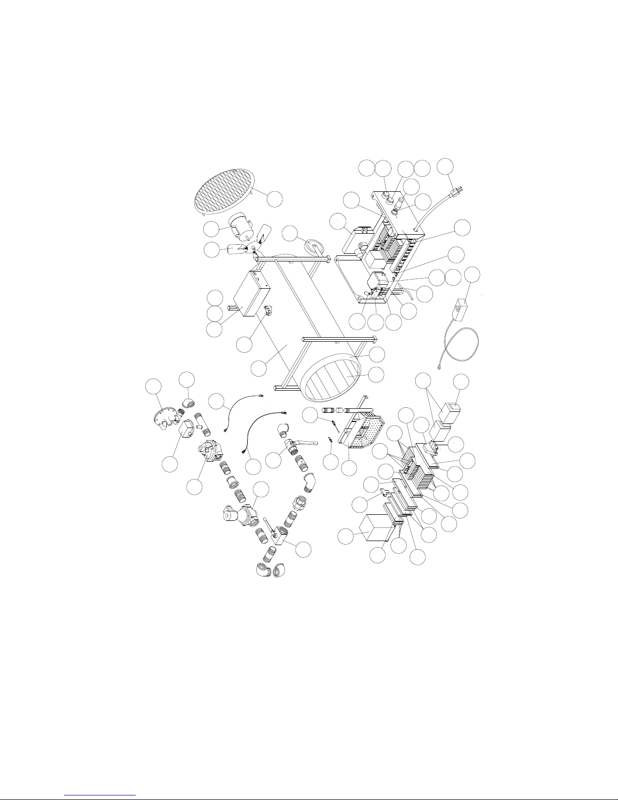
Replacement Parts
D2
D17
D3
D15
D13
D11
D8 D5
D6
D7
D10
D19
D4
D12 D22
D20
D21
D18
D14
D16
D1
D9
D23
C20
C3
C9
C8 C6
C5
C10
C11
C12
C14
C17
C15
C19
C18
C1
C7
C4
C13
C16
A8
A3 A6 A7
A9
A4 A5
A1
A10
A11
B1
A2
B2
B3
B10
B9
B8
B7
B6
B5
B4
D24
Table of contents
Other Sure Flame Heater manuals

Sure Flame
Sure Flame ID400 User manual

Sure Flame
Sure Flame IX405 User manual

Sure Flame
Sure Flame IX4 User manual

Sure Flame
Sure Flame ID 100 User manual

Sure Flame
Sure Flame S400 Installation and user guide

Sure Flame
Sure Flame SE405 Installation and user guide

Sure Flame
Sure Flame SL11B Installation and user guide

Sure Flame
Sure Flame SE400 User manual

Sure Flame
Sure Flame S2200D User manual

Sure Flame
Sure Flame IX800 User manual


