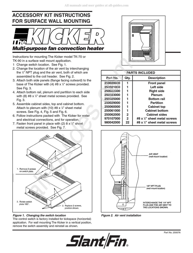
Slant/Fin Kicker TK-70 User manual
Other Slant/Fin Heater manuals
Popular Heater manuals by other brands

oventrop
oventrop Regucor Series quick start guide

Blaze King
Blaze King CLARITY CL2118.IPI.1 Operation & installation manual

ELMEKO
ELMEKO ML 150 Installation and operating manual

BN Thermic
BN Thermic 830T instructions

KING
KING K Series Installation, operation & maintenance instructions

Empire Comfort Systems
Empire Comfort Systems RH-50-5 Installation instructions and owner's manual

Well Straler
Well Straler RC-16B user guide

EUROM
EUROM 333299 instruction manual

Heylo
Heylo K 170 operating instructions

Eterna
Eterna TR70W installation instructions

Clarke
Clarke GRH15 Operation & maintenance instructions

Empire Heating Systems
Empire Heating Systems WCC65 Installation and owner's instructions


