Elektron Analog Heat MKII User manual

Analog
Heat
Stereo Analog Sound Processor
User Manual

FCC compliance statement
This device complies with part 15 of the FCC rules. Operation is subject to the following two conditions:
(1) This device may not cause harmful interference, and (2) this device must accept any interference
received, including interference that may cause undesired operation.
NOTE: This equipment has been tested and found to comply with the limits for a Class B digital device,
pursuant to Part 15 of the FCC Rules. These limits are designed to provide reasonable protection
against harmful interference in a residential installation. This equipment generates, uses and can
radiate radio frequency energy and, if not installed and used in accordance with the instructions, may
cause harmful interference to radio communications. However, there is no guarantee that interference
will not occur in a particular installation. If this equipment does cause harmful interference to radio or
television reception, which can be determined by turning the equipment o and on, the user is encour-
aged to try to correct the interference by one or more of the following measures:
• Reorient or relocate the receiving antenna.
• Increase the separation between the equipment and receiver.
• Connect the equipment into an outlet on a circuit dierent from that to which the receiver is
connected.
• Consult the dealer or an experienced radio/TV technician for help.
European Union regulation compliance statement
This product has been tested to comply with the Low Voltage Directive 2006/95/EC and the
Electromagnetic Compatibility Directive 2004/108/EC. The product meets the requirements of RoHS 2
Directive 2011/65/EU.
Your product must be disposed of properly according to local laws and regulations.
Legal disclaimer
The information in this document is subject to change without notice and should not be construed as a
commitment by Elektron. Elektron assumes no responsibility for any errors that may appear in this doc-
ument. Elektron may also make improvements and/or changes in the products and programs described
in this document at any time without notice. In no event shall Elektron be liable for any special, indirect,
or consequential damages or any damages whatsoever resulting from loss of use, data, or profits,
whether in an action of contract, negligence, or other action, arising out of or in connection with the use
or performance of this information.
Canada
This Class B digital apparatus complies with Canadian ICES-003.
Cet appareil numérique de la classe B est conforme à la norme NMB-003

IMPORTANT SAFETY AND MAINTENANCE INSTRUCTIONS
Please read these instructions carefully and follow the operating advice given here.
1. Do not use this unit near water.
2. Never use aggressive cleaners on the casing or the LCD screen. Remove dust, dirt and fingerprints with
a soft, dry and non-abrasive cloth. More persistent dirt can be removed with a slightly damp cloth using
only water. Disconnect all cables before doing this. Only reconnect them when the product is safely dry.
3. Install by following the manufacturer’s instructions. Make sure you place the unit on a stable surface
before use.
4. Connect the unit to an easily accessible electrical outlet close to the unit.
5. When transporting the unit, use accessories recommended by the manufacturer or the original box and
padding.
6. Do not install near any heat sources such as radiators, heat registers, stoves, or any other equipment
(including amplifiers) producing heat.
7. Do not block the ventilation holes located on the bottom of the enclosure of the unit.
Make sure there is sucient air circulation in the room where the unit is kept.
8. This product, in combination with an amplifier and speakers or headphones, is capable of producing
sound levels that can cause permanent hearing loss. Do not operate for extended periods of time at a
high volume level or at a level that is uncomfortable.
9. Protect the power cord from being walked on or pinched particularly at plugs, convenience receptacles,
and the point where they exit from the unit.
10.Use attachments/accessories specified by the manufacturer.
11. Unplug this unit during lightning storms or when it is not used for extended periods of time.
12.Refer all servicing to qualified service technicians. Servicing is required when the unit has been
damaged in any way, liquid has been spilled or objects have fallen into the unit, the unit has been
exposed to rain or moisture, does not operate normally, or has been dropped.
WARNING
To reduce the risk of fire, electrical shock or product damage:
• Do not expose the unit to rain, moisture, dripping or splashing and also avoid placing objects filled with
liquid, such as vases, on the unit.
• Do not expose the unit to direct sunlight, nor use it in ambient temperatures exceeding 35°C as this can
lead to malfunction.
• Do not open the casing. There are no user repairable or adjustable parts inside. Leave service and re-
pairs to trained service technicians only.
• Do not exceed the limitations specified in the Electrical specifications.
SAFETY INSTRUCTIONS FOR THE POWER ADAPTER ELEKTRON PSU-3b
• The adapter is not safety grounded and may only be used indoors.
• To ensure sucient ventilation for the adapter, do not place it in tight spaces. To prevent the risk of elec-
tric shock and fire because of overheating, ensure that curtains and other objects do not prevent adapter
ventilation.
• Do not expose the power adapter to direct sunlight, nor use it in ambient temperatures exceeding 40°C.
• Connect the adapter to an easily accessible electrical outlet close to the unit.
• The adapter is in standby mode when the power cord is connected. The primary circuit is always active
as long as the cord is attached to the power outlet. Pull out the power cord to completely disconnect the
adapter.
• In the EU, only use CE approved power cords.


TABLE OF CONTENTS
5
TABLE OF CONTENTS
. INTRODUCTION ....................................................................................7
. CONVENTIONS IN THIS MANUAL ............................................................ 7
. PANEL LAYOUT AND CONNECTIONS .......................................................... 8
. FRONT PANEL CONTROLS ..................................................................8
. REAR PANEL CONNECTIONS ...............................................................9
. FIRST STEPS WITH THE ANALOG HEAT ...................................................... 10
. CONNECTING THE UNIT.................................................................... 10
. SETTING THE INPUT SENSITIVITY LEVEL .................................................. 10
. SETUP EXAMPLES .........................................................................11
3.3.1 ANALOG HEAT AS AN EXTERNAL EFFECT .................................................11
3.3.2 ANALOG HEAT AS A VST/AU PLUGIN USING OVERBRIDGE .................................11
3.3.3 ANALOG HEAT AS A SOUND CARD ........................................................11
. SIGNAL FLOW.................................................................................... 12
. AUDIO SIGNAL FLOW ...................................................................... 12
. MODULATION SIGNAL FLOW .............................................................. 12
. THE USER INTERFACE .......................................................................... 12
. PRESETS .................................................................................. 12
5.1.1 LOADING A PRESET .......................................................................12
5.1.2 SAVING A PRESET ........................................................................13
. ACTIVE MODE ............................................................................. 13
. EFFECT CIRCUITS ......................................................................... 13
. FILTER TYPES............................................................................. 13
. EQUALIZER ............................................................................... 13
. DRIVE ..................................................................................... 14
. WET LEVEL................................................................................ 14
. DRY/WET ................................................................................. 14
. SETTINGS MENU .......................................................................... 14
. PARAMETER PAGES ...................................................................... 14
. PARAMETER EDITING ..................................................................... 14
. LCD SCREEN TITLE BAR .................................................................. 14
. OVERBRIDGE ............................................................................. 15
. THE SETTINGS MENU........................................................................... 15
. INPUT SENSITIVITY ........................................................................ 15
. MODULATION ............................................................................. 16
. OPTIONS.................................................................................. 16
6.3.1 INTERNAL TEMPO ........................................................................16
6.3.2 ACTIVE AT START ........................................................................16
6.3.3 ANALOG IN/OUT .........................................................................16
6.3.4 KNOB MODE ............................................................................. 17
. CONTROL IN .............................................................................. 17
6.4.1 CONTROL IN A. . . . . . . . . . . . . . . . . . . . . . . . . . . . . . . . . . . . . . . . . . . . . . . . . . . . . . . . . . . . . . . . . . . . . . . . . . . . 17
6.4.2 CONTROL IN B ........................................................................... 17
. MIDI....................................................................................... 18
6.5.1 SYNC .....................................................................................18
6.5.2 PORT CONFIG ...........................................................................18
6.5.3 CHANNELS ..............................................................................19

TABLE OF CONTENTS
6
. SYSTEM ................................................................................... 19
6.6.1 USB CONFIG..............................................................................19
6.6.2 USB AUDIO CONFIG......................................................................19
6.6.3 OS UPGRADE ............................................................................19
6.6.4 CALIBRATION ............................................................................19
. PARAMETER PAGES. . . . . . . . . . . . . . . . . . . . . . . . . . . . . . . . . . . . . . . . . . . . . . . . . . . . . . . . . . . . . . . . . . . . . . . . . . . . .20
. AMP PAGE .................................................................................20
7.1.1 DRIVE .....................................................................................20
7.1.2 WET ......................................................................................20
7.1.3 DRY/WET .................................................................................20
7.1.4 VOL.......................................................................................20
. FILTER/EQ PAGE 1 .........................................................................20
7.2.1 FREQ .....................................................................................20
7.2.2 RESO ....................................................................................21
7.2.3 ENV ......................................................................................21
7.2.4 LFO ......................................................................................21
. FILTER/EQ PAGE 2 ......................................................................... 21
7.3.1 FRQPAN ..................................................................................21
7.3.2 DIRT .....................................................................................21
7.3.3 EQ LO ....................................................................................21
7.3.4 EQ HI.....................................................................................21
. ENVELOPE PAGE 1 ......................................................................... 21
7.4.1 MODE.....................................................................................22
7.4.2 ATK ......................................................................................22
7.4.3 REL ......................................................................................23
7.4.4 TRIG .....................................................................................23
. ENVELOPE PAGE 2.........................................................................23
7.5.1 BASE .....................................................................................23
7.5.2 WIDTH ...................................................................................23
7.5.3 DEST1 ....................................................................................23
7.5.4 DEPTH1 ..................................................................................24
. LFO PAGE 1 ................................................................................24
7.6.1 SPEED ....................................................................................24
7.6.2 MULT.....................................................................................24
7.6.3 WAVE ....................................................................................24
7.6.4 START....................................................................................24
. LFO PAGE 2 ................................................................................24
7.7.1 FADE......................................................................................25
7.7.2 MODE ....................................................................................25
7.7.3 DEST1 ....................................................................................25
7.7.4 DEPTH1...................................................................................25
. TIPS & TRICKS ...................................................................................25
. ADDING SATURATION TO THE HIGH REGISTER .............................................25
. PSEUDO-COMPRESSION ..................................................................25
8.3 STEREO PHASER EFFECT .................................................................26
9. EARLY STARTUP MENU.........................................................................27
9.1 TEST MODE ................................................................................27
9.2 EMPTY RESET.............................................................................27
9.3 FACTORY RESET ..........................................................................27
9.4 OS UPGRADE..............................................................................27

TABLE OF CONTENTS
7
. INTRODUCTION
Thank you for purchasing Analog Heat. The Analog Heat is a stereo analog sound processor with many
great features such as; 8 dierent analog eect circuits, an analog multimode filter, analog EQ, and support
for Elektron’s groundbreaking software suite Overbridge.
Its innovative combination of modern technology and tried and trusted ways of analog sound processing
lets you add sparkly brilliance, or grimy roughness, to any sound source. Samplers, drum machines, synths,
the master bus, you name it. Analog Heat is a fiery furnace destined to make your music glow and sizzle.
Please read this manual in its entirety to get the most out of your machine.
. CONVENTIONS IN THIS MANUAL
We have used the following conventions throughout the manual:
Key names are written in upper case, bold style and within brackets. For instance, the key labeled “Settings”
on the main panel is written as [SETTINGS].
Knobs are written in upper case, bold, italic letters. For instance, the knob “Frequency” is called
FREQUENCY.
LED indicators like the Active LED are written like this: <ACTIVE>.
Menu names are written in upper case letters. The AMP menu is an example of that.
Parameter names and certain menu options where settings are made or actions performed are written in
bold, upper case letters. For example, ATTACK.
Upper case letters are used for parameter setting alternatives, for example, OFF.
Messages visible on the screen are written in upper case letters with quotation marks. For example,
“INPUT LEVEL TOO HIGH!”.
The manual uses the following symbols:
Important information that you should pay attention to.
A tip that makes it easier for you to interact with Analog Heat.
The right ear. Nobody wants the wrong one.
Analog Heat User Manual. This manual is copyright © 2018 Elektron Music Machines MAV AB. All reproduction without
written authorization is strictly prohibited. The information in this manual may change without notice. Elektron’s product
names, logotypes, titles, words or phrases may be registered and protected by Swedish and international law.
All other brand or product names are trademarks or registered trademarks of their respective holders. This manual for
Analog Heat OS version 1.10 was last updated July 5, 2018.
. TECHNICAL INFORMATION ...................................................................28
. CREDITS AND CONTACT INFORMATION.....................................................28
APPENDIX A: MIDI..................................................................................29
APPENDIX B: MODULATION SOURCES AND DESTINATIONS ................................30
INDEX................................................................................................ 31
2. PANEL LAYOUT AND CONNECTIONS
8
. PANEL LAYOUT AND CONNECTIONS
. FRONT PANEL CONTROLS
12
14
1119
9
8
10
7
13
15161718
654321
20
21
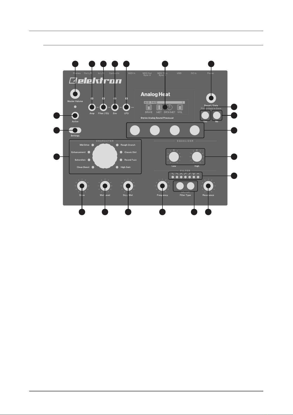
1. MASTER VOLUME sets the master volume for the L/R and Headphones outputs.
2. [AMP] key accesses the AMP parameter page where you can set things such as drive amount and the
volume of the preset.
3. [FILTER/EQ] key accesses the FILTER/EQ parameter pages where you, among other things, can set
the filter frequency cuto, and adjust the equalizer. Press twice to access the second page.
4. [ENV] key accesses the ENV parameter pages where you adjust the settings for the envelope genera-
tor/envelope follower. Press twice to access the second page.
5. [LFO] key accesses the LFO parameter pages where you set all things related to the Low Frequency
Oscillator. Press twice to access the second page.
6. The LCD screen.
7. PRESET/DATA Used for preset management, such as Save and Load, and data entry.
8. [YES] key is used for entering sub-menus, selecting and confirming.
9. [NO] key is used for exiting the current menu, backing to a higher level menu and negating.
10. DATA ENTRY knobs. Used to set parameter values. Press the knob when turning to change values in
larger increments. For more information, please see "5.11 PARAMETER EDITING" on page 14.
11. LOW and HIGH adjusts the amount of low-end and high-end frequency content.
12. <FILTER TYPE> LEDs that indicate the current type of filter and also if the filter is on or not.
13. RESONANCE sets the resonance of the filter.
14. [FILTER TYPE] selects between the dierent filter types. Also, pressing both keys at the same time
toggles the filter on and o.
15. FREQUENCY sets the filter’s cuto frequency.
16. DRY/WET sets the balance between the unprocessed (dry) signal and the processed (wet) signal.
17. WET LEVEL sets the level of the processed (wet) signal.
18. DRIVE controls the amount of drive. It increases the eect (distortion) of the selected circuit type.
19. CIRCUIT SELECTOR chooses between the eight dierent types of analog eect circuits.
20.[SETTINGS] key accesses the SETTINGS menu. See "6. THE SETTINGS MENU" on page 15.
21. [ACTIVE] toggles the eect between active and bypassed.

2. PANEL LAYOUT AND CONNECTIONS
9
. REAR PANEL CONNECTIONS
1 2 3 4 5 6 7 8 9 10
1. POWER, Switch for turning the unit on and o.
2. DC In, Input for power supply. Use the included PSU-3b power adapter, connected to a power outlet.
3. USB, For connecting the unit to a computer. For MIDI-control or Overbridge use. Connect to a
computer host using the included A to B USB 2.0 connector cable.
4. MIDI THRU/SYNC B, Forwards data from MIDI IN. Can also be configured to send DIN sync to legacy
instruments. Use standard MIDI cable to connect another MIDI unit in the chain.
5. MIDI OUT/SYNC A, MIDI data output. Can also be configured to send DIN sync to legacy instruments.
Use standard MIDI cable to connect to MIDI In of an external MIDI unit.
6. MIDI IN, MIDI data input. Use standard MIDI cable to connect to MIDI Out of an external MIDI unit.
7. CONTROL IN A/B Inputs for an expression pedal, footswitch, or CV. Use 1/4” mono phone plug for CV
signals.
8. INPUT L/R, Audio inputs. Use either 1/4” mono phone plug (unbalanced connection) or 1/4” (Tip/Ring/
Sleeve) phone plug (balanced connection).
9. OUTPUT L/R, Main audio outputs. Use either 1/4” mono phone plug (unbalanced connection) or 1/4”
(Tip/Ring/Sleeve) phone plug (balanced connection).
10. HEADPHONES, Audio output for stereo headphones. Use 1/4” (Tip/Ring/Sleeve) phone plug.
3. FIRST STEPS WITH THE ANALOG HEAT
10
. FIRST STEPS WITH THE ANALOG HEAT
. CONNECTING THE UNIT
Make sure you place the Analog Heat on a stable support, such as a sturdy table with sucient cable
space. Before you start connecting the Analog Heat to other units, make sure all units are switched o.
1. Plug the supplied DC adapter to a power outlet and connect the small plug to the 12 V DC connector
of the Analog Heat unit.
2. Connect the audio source to INPUT L/R.
3. Connect the OUTPUT L/R from the Analog Heat to your mixer or amplifier.
4. To process sound and/or control the Analog Heat from a computer, connect a USB cable between the
computer and the USB connector of the Analog Heat. You must also download and install the Overbridge
Suite to perform these actions.
5. If you want to use MIDI to control the Analog Heat, connect the MIDI OUT port of the device you wish to
send data from to the MIDI IN port of the Analog Heat. You can use the MIDI THRU port for chaining MIDI
devices together since it duplicates the data arriving at the MIDI IN port.
6. Switch on all units. Switch on the Analog Heat by pressing the Power switch located at the back of the
device.
. SETTING THE INPUT SENSITIVITY LEVEL
To make sure the Heat distorts as intended it is important to adjust the audio input sensitivity
level so that it matches the level of the sound source.
To make sure the Heat distorts as intended it is important to set the audio input sensitivity so that it match-
es the level of the sound source. (Note that the settings made here only aects the analog input, and not
the digital input from Overbridge.) Follow these steps to set the input sensitivity level:
1. Connect your sound source to the IN L/R inputs of the Analog Heat and make sure that the volume of
the sound source is as strong as possible.
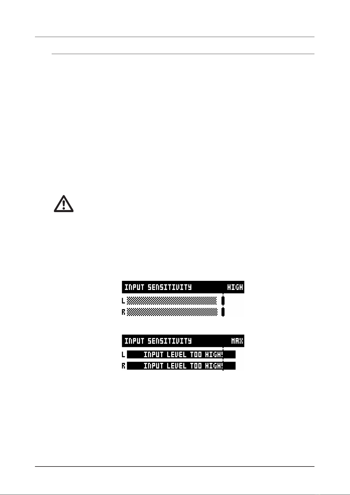
2. Press [SETTINGS] and then select INPUT SENSITIVITY. Keep an eye on the audio input meter and
change the input sensitivity until you find a setting where the bar reaches the vertical line but without
clipping. The message “INPUT LEVEL TOO HIGH” is displayed on the LCD screen when the input level is
too high, and clipping occurs.
Optimal input level.
Too high input level.
3. Adjust the level at the sound source if needed.

3. FIRST STEPS WITH THE ANALOG HEAT
11
. SETUP EXAMPLES
The Analog Heat is very well suited for use in both an analog setup and in a more digital environment. Here
are a couple of examples of how you can use the Analog Heat. For additional information about how to set
up Analog Heat in dierent configurations, please see "6.3.3 ANALOG IN/OUT" on page 16.
3.3.1 ANALOG HEAT AS AN EXTERNAL EFFECT
In this example, the Analog Heat is used as an external eect to add color to the Elektron Octatrack
before the signal reaches the mixer.
3.3.2 ANALOG HEAT AS A VST/AU PLUGIN USING OVERBRIDGE
Analog Heat can also be used together with Overbridge to allow you to use the Analog Heat as a plugin
for analog distortion processing in your DAW.
3.3.3 ANALOG HEAT AS A SOUND CARD
Analog Heat also functions as a 2 in/2 out sound card for your computer and can be used for both
recording and monitoring audio. At the same time you can, via Overbridge, also use the eect to process
another set of audio signals.

4. SIGNAL FLOW
12
. SIGNAL FLOW
The illustrations below show the signal flows of the Analog Heat and illustrates how the dierent compo-
nents interact with each other.
. AUDIO SIGNAL FLOW
This illustration shows the general flow of audio through the Analog Heat. The complete signal chain is in
stereo.
In L/R
Input
Sensitivity
Eect
Wet level Dry/Wet
Mix
Preset
Volume
Master
Volume
Out L/R
Head-
phones
Circuit
DirtDrive
Multi-mode
Filter Equalizer
Overbridge
Bypass
. MODULATION SIGNAL FLOW
This illustration shows the flow of how modulation signals are generated and routed through the
Analog Heat.
In L/R
Input
Sensitivity
Bandpass
Filter
Envelope
Follower
Gain
Filter
Modulation
Modulation
Destination
Compar-
ator
LFO Modulation
Destination
Modulation
Destination
Trig
Filter
Modulation
Filter
Modulation
Envelope
Generator
Over-
bridge
. THE USER INTERFACE
. PRESETS
The Analog Heat has 128 preset slots where you can store your presets. Preset slot 000 is an INIT preset
with default values. Note that, when switching o the power on your Heat, any changes to the currently
active preset will be lost unless the preset is first saved. There is an indicator (next to the preset number)
on the LCD screen showing when changes have been made to the preset. For more information, please see
"5.12 LCD SCREEN TITLE BAR" on page 14.
5.1.1 LOADING A PRESET
1. Turn PRESET/DATA to select a preset.
2. Press PRESET/DATA or [YES] to load the preset.

5. THE USER INTERFACE
13
5.1.2 SAVING A PRESET
1. Press and hold PRESET/DATA for two seconds. The selected preset now starts to blink to illustrate
that you are about to overwrite a preset position.
2. Turn PRESET/DATA to select the preset slot to where you want to save your sound, and then press
[YES]
3. (Optional) Turn PRESET/DATA to the character you wish to edit. Press and hold [SETTINGS] and
then turn PRESET/DATA to move the cursor to the desired character and select it by releasing [SET-
TINGS]. To delete a character, turn PRESET/DATA to move the cursor to highlight the character after
the one you wish to delete, then press and hold [SETTINGS] and press [NO] twice.
4. Press [YES] to save the preset.
. ACTIVE MODE
Active Mode is toggled on and o by pressing [ACTIVE]. If the Analog Heat is not in Active Mode, the eect
is bypassed. The <ACTIVE> LED indicates if the eect is active or not. You can also use a Footswitch to
toggle the Active Mode. For more information, please see "6.4 CONTROL IN" on page 17. You also have
the option to set if you want the Analog Heat to start in active mode or not when you turn it on. For more
information, please see "6.3.2 ACTIVE AT START" on page 16.
. EFFECT CIRCUITS
You can use the CIRCUIT SELECTOR to choose between 8 dierent types of eect circuits
for a wide variety of drive and distortion sounds.
• CLEAN BOOST
Makes the signal louder. When fully driven, it sounds similar to overdriving old mixers. Use for minimal
distortion or when you only want to use the filter and EQ.
• SATURATION
This circuit is reminiscent of classic tape saturation. Woolly and warm.
• ENHANCEMENT
Adding tube-like glow and sheen to a track or loop.
• MID DRIVE
Mid-range focused overdrive with a solid and distinct body.
• ROUGH CRUNCH
Gritty, worn and gnarly character. Full of flavor.
• CLASSIC DIST
Pleasantly distorts upper mid-range frequencies. Ideal for acid bass lines.
• ROUND FUZZ
Adds a lot of harmonics and alters the signal in interesting and often unpredictable ways.
• HIGH GAIN
Probably the most aggressive of all the circuits. Very maxed out!
. FILTER TYPES
Change the type of the filter by pressing one of the two [FILTER TYPE] keys. You can also press the two
[FILTER TYPE] keys simultaneously to toggle the filter on/o. It is possible to change the filter type even if
the filter is turned o.
There are seven dierent analog filter types in the Analog Heat to help to shape the sound.
• LOW PASS 2 (two-pole, 12 dB per octave)
• LOW PASS 1 (one-pole, 6 dB per octave)
• BAND PASS
• HIGH PASS 1 (one-pole, 6 dB per octave)
• HIGH PASS 2 (two-pole, 12 dB per octave)
• BAND STOP (NOTCH)
• PEAK
. EQUALIZER
LOW and HIGH adjusts the amount of low-end and high-end frequency gain or attenuation of the
eect circuit. Each character circuit comes with its tailor-made equalizer characteristics. For more informa-
tion, please see "4.1 AUDIO SIGNAL FLOW" on page 12.
5. THE USER INTERFACE
14
. DRIVE
Sets the gain level in the eect circuit. A higher setting increases the eect of the selected circuit type,
typically resulting in more distortion. For more information, please see "4. SIGNAL FLOW" on page 12.
. WET LEVEL
Sets the level of the signal coming from the eect. It is applied before the DRY/WET mix. It is used to match
the level of the dry signal for easy mixing of the two. For more information, please see "4. SIGNAL FLOW"
on page 12.
. DRY/WET
Sets the mix between the clean signal and the signal that is aected by the eect. For more information,
please see "4. SIGNAL FLOW" on page 12.
. SETTINGS MENU
Press [SETTINGS] to access the SETTINGS menu.
Scroll through the list of settings by using the PRESET/DATA knob. Open a highlighted menu by pressing
the PRESET/DATA knob or [YES]. To change the settings in the menus, first press and then turn the PRE-
SET/DATA knob. For more information, please see "6. THE SETTINGS MENU" on page 15.
. PARAMETER PAGES
Access the parameter pages by pressing the corresponding key [AMP], [FILTER/EQ], [ENV], and [LFO].
There are two pages associated with each key (AMP has only one page). You can access the secondary
pages by pressing the [PARAMETER] key a second time. For more information, please see "7. PARAMETER
PAGES" on page 20.
. PARAMETER EDITING
The four DATA ENTRY knobs are used to change the parameter values that are shown on the LCD screen.
(Some parameters also have dedicated knobs on the panel.) The physical location of the knobs on the front
panel correspond to the layout of the parameters on the screen.
• Press down and turn the DATA ENTRY to adjust the parameters in larger increments.
• Press [SETTINGS] + turn DATA ENTRY knob to quantize the parameter value to integers.
• Press [NO] +DATA ENTRY knob to reset the parameter to the default value.
• Press [NO] +[PARAMETER] key to reset the selected parameter group to default values.
• Use the [NO] key to exit an active menu, back to a higher level menu and to negate.
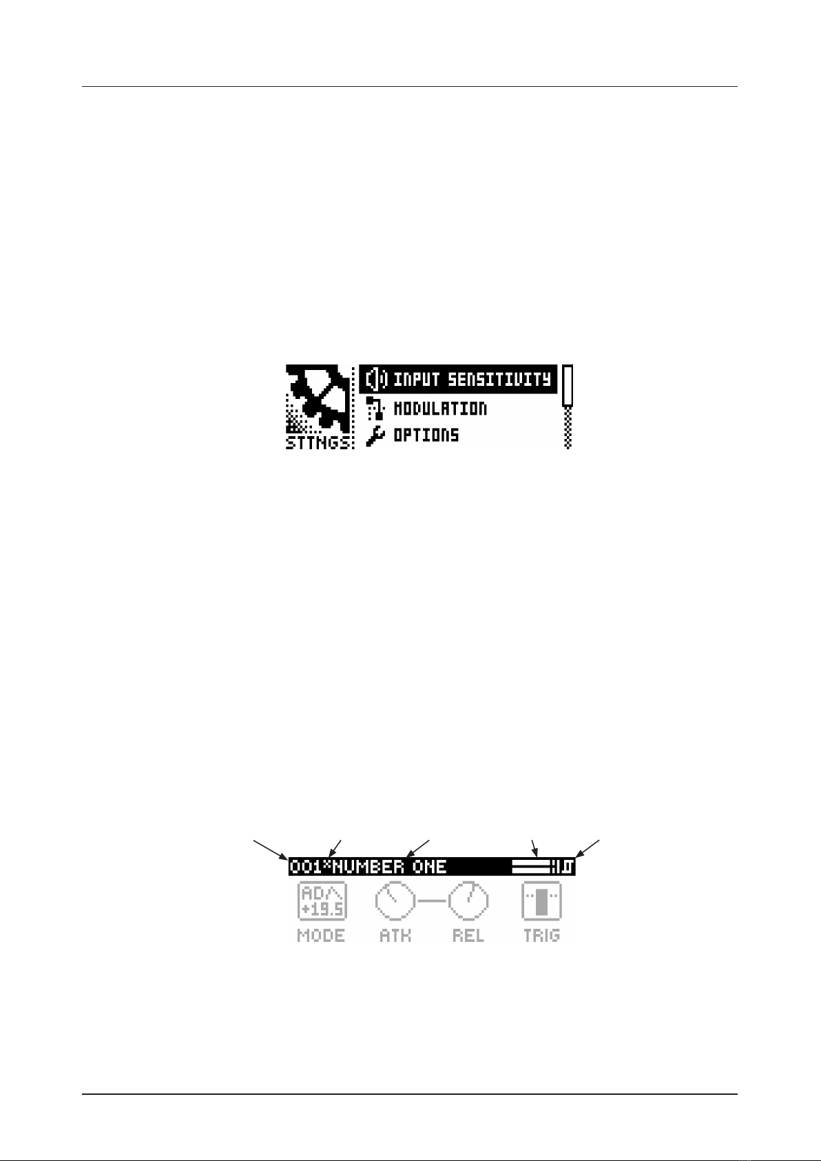
. LCD SCREEN TITLE BAR
Preset number Preset nameChange indicator Audio input meter Trigger icon
• The Preset number and Preset name displays the currently selected preset. If you push one of the pa-
rameter keys, the title bar briefly shows the name of the active parameter page. This text is replaced by
parameter names when turning the DATA ENTRY knobs or the dedicated controllers.
• Between the preset number and the preset name, there is an indicator showing if the preset has been
altered. (i.e. changes that may be lost unless you save the preset.)
• The Audio input meter displays the level of the incoming audio.
• The Trigger icon signals that a trigger event has been generated by the Envelope Follower.
6. THE SETTINGS MENU
15
. OVERBRIDGE
This manual primarily focuses on how to use the Analog Heat as a standalone eect. But you can also use
Overbridge to interact with the Analog Heat. The Overbridge software suite enables a tight integration be-
tween the Analog devices (Analog Rytm, Analog Keys, Analog Four, Analog Heat) and a computer DAW.
N.B. You must have Analog Heat OS 1.02 or later, and Overbridge 1.15 or later to run Overbridge with
Analog Heat.
Overbridge allows you to use the Analog Heat as a VST/AU plugin for analog distortion and filter processing
in your DAW.
It also has a librarian for a clear overview of your presets and gives the ability to load, edit, and save them.
When using the Overbridge setup, the user interface for your Analog device will present itself as a clearly
laid out plug-in window in your DAW. Browse through and organize presets. Access, edit or automate pa-
rameters for sound shaping on screen. Always find your device preset parameters in the same state as you
left them when you return to your DAW project, with the convenient total recall functionality.
You need an Analog Heat, a USB cable, a computer running Overbridge, and a DAW.
If you want to hook up multiple machines to a computer, you must use a USB hub. We suggest the Elektron
Overhub, tailored for Overbridge use. It is Multi-TT hub and thereby also supports older Elektron machines.
Overbridge is available as a complimentary download on the Elektron website. Please read the Overbridge
manual (also available on the Elektron website, Support section) to learn more about its uses and capabilities.
Once installed, for Overbridge to work together with your Analog Heat, do the two following two things:
First - Make sure the OS of your Analog Heat, and the OS of Overbridge, match. Simply put, always have
the most recent OS installed on both computer and device. You find the latest versions of both operating
systems included with the Overbridge Suite download package.
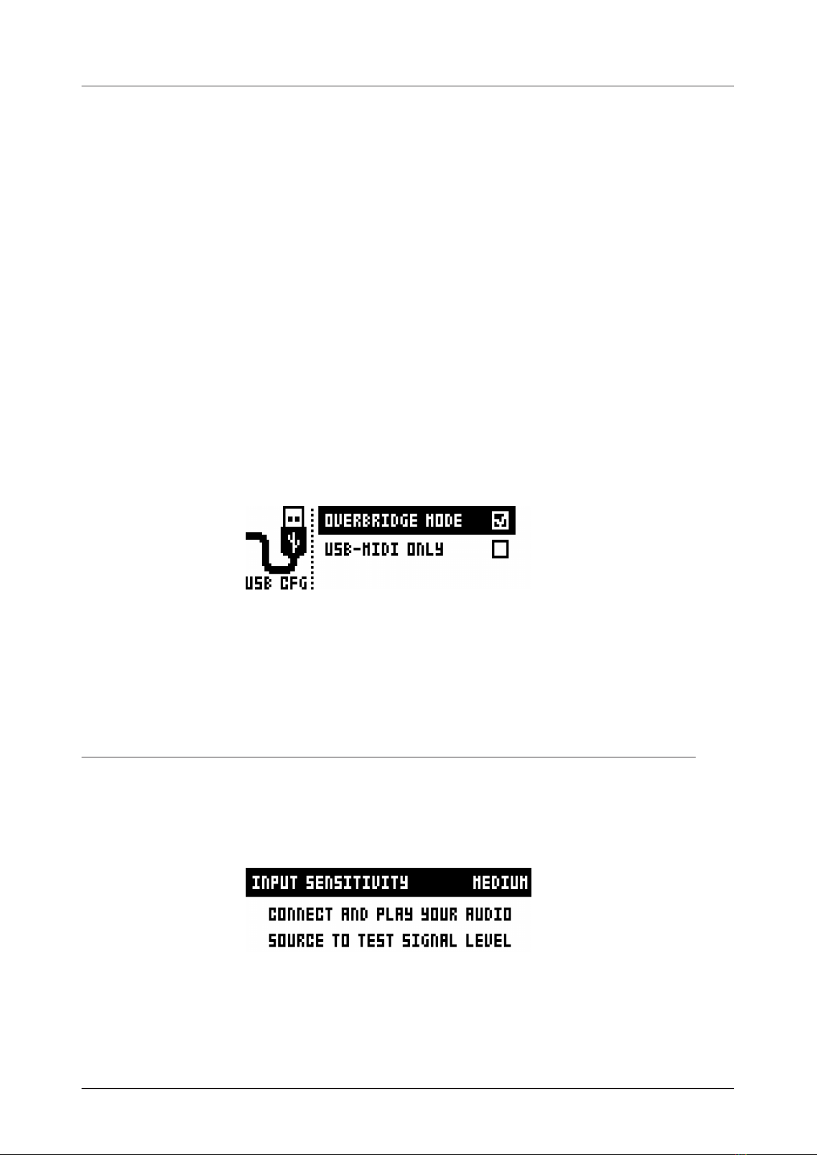
Second - set your Analog Heat device to Overbridge mode. You will find this setting in the SETTINGS >
SYSTEM > USB CONFIG menu. Press [YES] to tick the OVERBRIDGE box. For more information, please
see "6.6.1 USB CONFIG" on page 19.
For more detailed information about installing and using Overbridge, please see the Overbridge User Manual
that you can download from the Elektron website.
. THE SETTINGS MENU
Here follows a description of all the parameters that are in the SETTINGS menu. You access the SETTINGS
menu by pressing the [SETTINGS] key. Scroll through the list of settings by using the PRESET/DATA knob.
Open a highlighted menu by pressing the PRESET/DATA knob or [YES]. To change the settings in the
menus, first press and then turn the PRESET/DATA knob.
. INPUT SENSITIVITY
Sets the audio input level to fit the audio level sent to the eect via the IN L/R inputs. It is important to set
this level correctly to get the best sound from your Analog Heat. There are four dierent settings for the
input sensitivity: LOW, MID, HIGH & MAX. Low is the most silent, Max is the loudest. For more information,
please see "3.2 SETTING THE INPUT SENSITIVITY LEVEL" on page 10.
• LOW (Maximum input level 10,5 V, peak to peak)
• MID (Maximum input level 5,3 V, peak to peak)
6. THE SETTINGS MENU
16
• HIGH (Maximum input level 2,5 V, peak to peak)
• MAX (Maximum input level 1,2 V, peak to peak)
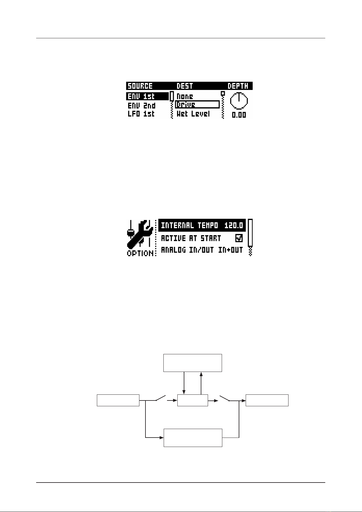
. MODULATION
Here you can connect a number of modulation sources with their destinations and set the modulation
depth. For more information, please see "APPENDIX B: MODULATION SOURCES AND DESTINATIONS" on
page 30.
1. Turn the PRESET/DATA knob to scroll through the source list, and then select it by pressing PRESET/
DATA or [YES].
2. Turn the PRESET/DATA knob to scroll through the available destinations, and then select it by pressing
PRESET/DATA or [YES].
3. Lastly, set the modulation depth amount by turning the PRESET/DATA knob. A negative value gives an
inverted modulation. You can also use the rightmost DATA ENTRY knob to set the modulation depth. To
reset the modulation amount to 0, press and hold [NO].
. OPTIONS
6.3.1 INTERNAL TEMPO
Sets the internal tempo. The tempo range is 30 – 300 BPM. This tempo controls the speed of the LFO.
The Analog Heat can also be set to respond to MIDI clock sent from external devices. If the device is
synced from either MIDI Clock or Overbridge, the Internal Tempo setting is locked from editing, and this
parameter instead shows the sync source together with the currently active (external) tempo. For more
information, please see "6.5.1 SYNC" on page 18.
6.3.2 ACTIVE AT START
Sets if Analog Heat is in Active or bypass mode when it is turned on.
6.3.3 ANALOG IN/OUT
Sets if the signal from the analog inputs is routed to the eect or not. It also sets if the signal from the
eect is routed analog outputs or not.
OVERBRIDGE
PLUGIN
EFFECT
OVERBRIDGE
AUDIO INTERFACE
ANALOG IN ANALOG OUT
IN OUT
Analog Input L/R Analog Output L/R
FX Return L/RFX Send L/R
Analog Heat supports 4 channels of audio. Analog Input L/R are routed to the analog in-, and outputs,
and can optionally also be routed through the eect. FX Send L/R are always routed to the eect.
6. THE SETTINGS MENU
17
• AUTO In Auto mode, Analog Heat automatically detects if the Overbridge plugin is running or not. With
Overbridge running, the Analog In is not routed through the eect to the Analog Out. (Same as OFF
setting.) If Overbridge is not running, the signal from analog is routed through the eect to the Analog
Out. (Same as IN+OUT setting.)
• IN+OUT Both Analog In and Analog Out are routed to the eect.
• IN Routs the signal from Analog In to the eect.
• OUT Routs the signal from the eect to Analog Out.
• OFF Neither Analog In nor Analog Out are routed to the eect.
You can use the Analog Heat as a regular audio interface and let signals pass in and out
unaected by the eect. At the same time you can, via Overbridge, also use the eect to
process another set of audio signals.
AUTO mode is suitable for most use-cases. It lets the Analog Heat function both as a
standalone eect and together with Overbridge as a plugin, while still retaining its func-
tionality as a sound card.
6.3.4 KNOB MODE
Sets how the knobs on the panel aect the parameters. When you load a preset, the knobs positions
typically don’t match their parameter values.
• JUMP immediately sets the value to the current knob position.
• In CATCH mode, turning the knob do not change the parameter value until the knob position matches
the presets stored value.
You can see the current value of the parameter in the LCD screens title bar while you turn the knob.
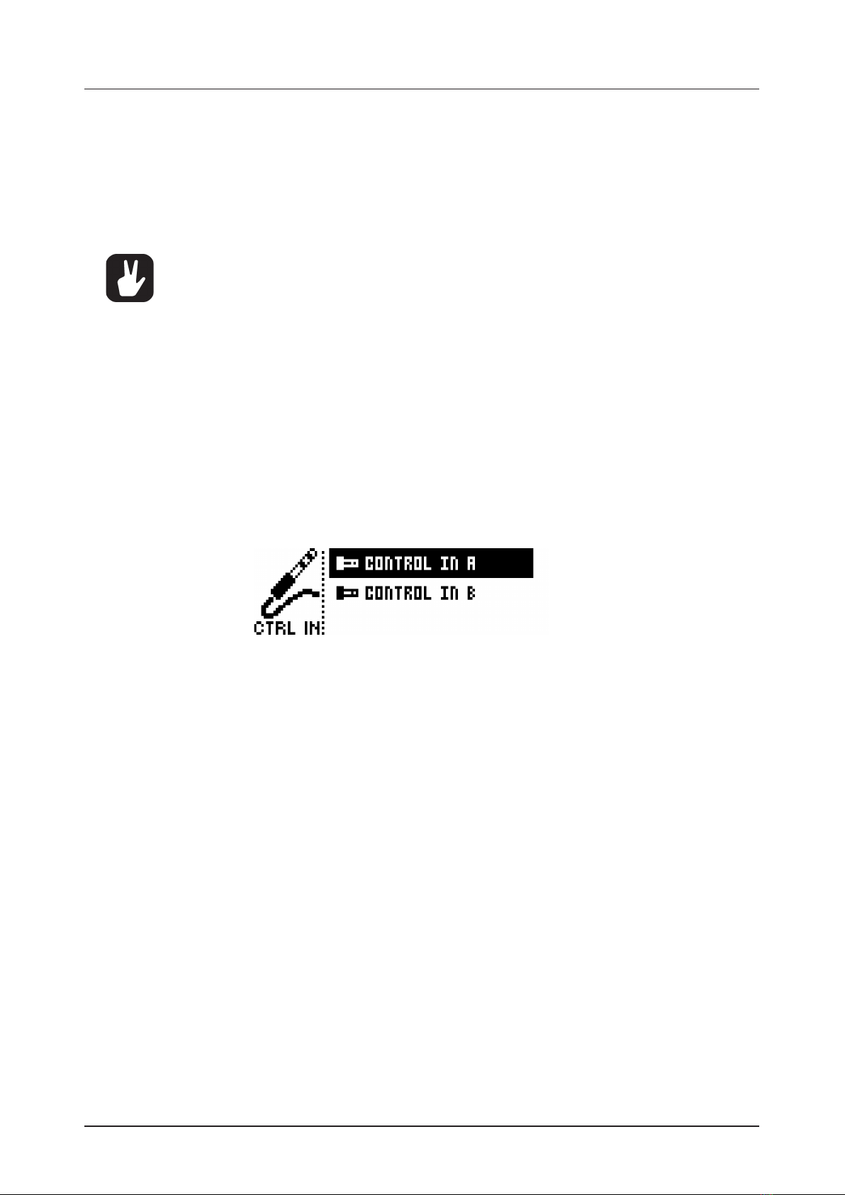
. CONTROL IN
6.4.1 CONTROL IN A
• CONTROL MODE
Sets the port mode to adjust to dierent kinds of input signals. There are four modes: CV (Control
Voltage), EXPR (Expression Pedal), FOOTSW (Footswitch) and OFF.
• CV ZERO LEVEL (Available when mode is set to CV.)
Sets the Volt level at which CV modulation amount is zero. A control input level equal to this setting
corresponds to zero modulation. (. V–+5.50 V).
• CV MAX LEVEL (Available when mode is set to CV.)
Sets the Volt level at which CV modulation amount is max. A control input level equal to this setting
corresponds to full modulation. (. V–+5.50 V).
• EXPRESSION LEARN (Available when mode is set to EXPR.)
Sets the highest and lowest limit of the control input level. When in this setting, connect the Expression
pedal to CONTROL IN A/B. Press YES and then move the expression pedal first to max and then to min
position. Press YES to save settings.
• REVERSE DIRECTION (Available when mode is set to EXPR.)
Reverses the direction of how the Expression pedal sends control input signals.
• FOOTSW DEST (Available when mode is set to FOOTSW.)
Sets the destination of the control input from the Footswitch. The options are: TEMPO, ACTIVE PRE-
SET +, PRESET , ENV TRIG
• FOOTSWITCH LEARN (Available when mode is set to FOOTSW.)
Sets the high and low limit of the control input level. When in this setting, connect the Footswitch pedal to
CONTROL IN A/B. Press YES and then press the Footswitch pedal a couple of times. Press YES to
save settings.
• REVERSE DIRECTION (Available when mode is set to FOOTSW.)
Reverses the direction of how the Footswitch pedal sends control input signals.
6.4.2 CONTROL IN B
The available settings are the same as for CONTROL IN A mentioned above.

6. THE SETTINGS MENU
18
. MIDI
These settings are stored in the global settings and are not part of the preset.
6.5.1 SYNC
• CLOCK RECEIVE
Sets whether or not the Analog Heat responds to MIDI clock and transport sent from external devices.
(ON, OFF)
• CLOCK SEND
Sets whether or not the Analog Heat sends/forwards MIDI Clock and transport. Transport is transmit-
ted when an external clock source (MIDI or Overbridge) is used. (ON, OFF)
• PROG CHG RECEIVE
Sets whether or not the Analog Heat responds to incoming program change messages. This is useful
when wanting to select presets from an external source For more information on how to select the
appropriate MIDI channel please see "6.5.3 CHANNELS" on page 19. (ON, OFF)
• PROG CHG SND
Sets whether or not the Analog Heat sends program change messages when it changes patches. For
more information on how to select the appropriate MIDI channel, please see "6.5.3 CHANNELS" on
page 19. (ON, OFF)
6.5.2 PORT CONFIG
• TURBO SPEED
This setting allows Turbo mode negotiation between Elektron gear. Connecting the Analog Heat to
other Turbo protocol compatible gear, like the Analog Rytm and the Octatrack, makes it possible to
increase the average MIDI bandwidth by up to 10x. This increases the accuracy of MIDI clock signals
as well as the timing of CC messages. (ON, OFF)
• OUT PORT FUNC
Sets what type of signal the MIDI OUT port sends.
• MIDI sets the port to send MIDI data.
• DIN24 sets the port to send DIN 24 sync pulses. No MIDI data can be sent on the port when this
option is selected.
• DIN48 sets the port to send DIN 48 sync pulses. No MIDI data can be sent on the port when this
option is selected.
• THRU PORT FUNC
Sets what type of signal the MIDI THRU port sends. The settings are the same as for OUT PORT
FUNC.
• INPUT FROM
Sets the source from which the Analog Heat receives MIDI data.
• MIDI Only receives MIDI data from the MIDI IN port.
• USB Only receives MIDI data from the USB port.
• MIDI+USB Receives MIDI data from both the MIDI IN and USB port.
• NONE Disregards any incoming MIDI data.
• OUTPUT TO
Selects the port to which Analog Heat sends MIDI data (CC or NRPN).
• MIDI Only sends MIDI data to the MIDI OUT port.
• USB Only sends MIDI data to the USB port.
• MIDI+USB Sends MIDI data to both the MIDI OUT and USB port.
• NONE Do not send MIDI data to any port.
• PARAM OUTPUT
Sets what type of MIDI messages the DATA ENTRY knobs sends. For information
about which CC/NRPN parameters that are sent, please see "APPENDIX A: MIDI" on page 29.
• CC Sets the knobs to send CC MIDI messages.
• NRPN Sets the knobs to send NRPN MIDI messages.
• ENCODER DEST
Sets whether or not the DATA ENTRY and LEVEL knobs send MIDI data.
• INT MIDI only sends data internally.
• INT + EXT MIDI sends data both internally and externally.

6. THE SETTINGS MENU
19
• PARAM INPUT
Makes it possible to control Analog Heat parameters from an external MIDI device sending CC/NRPN
data. (ON, OFF)
6.5.3 CHANNELS
• MIDI CHANNEL
Sets the MIDI channel that Analog Heat uses to send and receive MIDI data. When set to OFF, all MIDI
functionality is disabled. (1–16)
. SYSTEM
6.6.1 USB CONFIG
• USB-MIDI ONLY
If you wish to disable the Overbridge integration functionality, then select this option. (ON, OFF)
• OVERBRIDGE
To use the Analog Heat as an Overbridge device, select Overbridge mode. (ON, OFF)
6.6.2 USB AUDIO CONFIG
Here you can set the output level of the audio over USB when you use the Analog Heat as a sound card.
Select USB OUTPUT LEV and set the desired output level. This setting only aects Analog Out L/R
(OUTPUT L/R). (0 dB–+18 dB)
6.6.3 OS UPGRADE
This menu option is used to upgrade the Analog Heat OS. To send the OS syx file, use our free SysEx
utility software C6 (or other compatible SysEx software). You can download the OS syx file and the C6
software from the Elektron website.
For the transfer to be possible, the device sending the OS syx-file must be connected to either the MIDI
IN or USB port of the Analog Heat. Also, input from MIDI or USB must be enabled on the Analog Heat.
For more information, please see "6.5.2 PORT CONFIG" on page 18.
Please note that the Analog Heat do not appear as an icon on your computer desktop.
1. Download the OS syx file and the C6 software to your computer.
2. Select OS UPGRADE on the Analog Heat (If you wish to cancel the waiting state, press [NO].)
3. Open the C6 software. Click “Configure” and select Elektron Analog Heat for MIDI In as well as
MIDI Out.
4. Drag the OS syx file to the C6 main window, then highlight it by single-clicking it.
5. Click the “send” button in the top left corner of the C6 window.
When receiving the OS, a progress bar and the message "RECEIVING" is visible on the Analog Heat LCD
screen. When the bar is full, the message “ERASING FLASH” is shown on the screen. This takes a short
while. When this process is complete, the OS is updated, and the unit reboots.
If the Analog Heat is receiving the OS upgrade through the MIDI ports, use the Elektron
TM-1 USB MIDI interface for up to 10x higher transfer speeds.
6.6.4 CALIBRATION
CALIBRATION starts the calibration routine for the drive circuits and filters. After selecting this option,
a popup window appears asking to confirm the calibration. Press [YES] to proceed with the calibration.
Please note that the calibration routine takes quite a while to complete.

7. PARAMETER PAGES
20
The device should be turned on at least 2 hours before you perform a calibration for its
circuits to warm up properly. If the unit has not yet warmed up for 2 hours, there is a cal-
ibration countdown counter which automatically initiates the calibration once it reaches
the timeout.
Also, please note that nothing should be connected to the device during the calibration.
Remember to turn down the volume on all speakers and headphones before activating
Test mode.
Analog Heat is factory calibrated. It should not be re-calibrated unless specifically stated
by Elektron Support or if prompted by the machine.
. PARAMETER PAGES
Here follows a description of all the parameters that are on the PARAMETER pages. You access the param-
eter pages by pressing the [PARAMETER] keys. AMP has one page. FILTER/EQ, ENV, and LFO has two
pages. To access page one, press the [PARAMETER] key once. To access page two, press the [PARAME-
TER] key twice.
. AMP PAGE
Press [AMP] once to access this parameter page.
7.1.1 DRIVE
Sets the gain level of the audio into the distortion circuit. A higher setting results in more distortion. Even
at zero level some of the circuits have a clear eect on the sound. (0.00–127.00)
7.1.2 WET
Sets the level of the signal that is aected by the eect. Use WET LEVEL to balance the Wet part so
that it has a similar level to the Dry part. This makes it easier to use the (Dry/Wet) MIX parameter to do
parallel distortion. For more information, please see "4. SIGNAL FLOW" on page 12. (This parameter
is written as WET LEVEL on the device panel.) (0.00–127.00)
7.1.3 DRY/WET
Sets the mix between the clean signal and the signal that is aected by the eect. (64.00–63.00)
7.1.4 VOL
Sets the overall level of the sound and is saved as part of the preset. Use this to pick a good output gain
for the complete preset (i.e. from the output of the Dry/Wet mix). (0–127)
. FILTER/EQ PAGE 1
Press [FILTER/EQ] once to access this parameter page.
7.2.1 FREQ
Sets the cuto frequency of the filter. (0.00–127.00)
Other manuals for Analog Heat MKII
1
Table of contents
Other Elektron Recording Equipment manuals

Elektron
Elektron analog drive User manual

Elektron
Elektron Analog heat User manual

Elektron
Elektron Octatrack DPS-1 User manual

Elektron
Elektron Octatrack User manual

Elektron
Elektron Analog Heat MKII User manual

Elektron
Elektron Analog Heat +FX User manual

Elektron
Elektron Analog Heat +FX User manual

Elektron
Elektron MonoMachine SFX-6 Installation and operating instructions


