Elektron Analog Heat +FX User manual


FCC compliance statement
This device complies with part 15 of the FCC rules. Operation is subject to the following two conditions:
(1) This device may not cause harmful interference, and (2) this device must accept any interference
received, including interference that may cause undesired operation.
NOTE: This equipment has been tested and found to comply with the limits for a Class B digital device,
pursuant to Part 15 of the FCC Rules. These limits are designed to provide reasonable protection
against harmful interference in a residential installation. This equipment generates, uses and can
radiate radio frequency energy and, if not installed and used in accordance with the instructions, may
cause harmful interference to radio communications. However, there is no guarantee that interference
will not occur in a particular installation. If this equipment does cause harmful interference to radio or
television reception, which can be determined by turning the equipment o and on, the user is encour-
aged to try to correct the interference by one or more of the following measures:
• Reorient or relocate the receiving antenna.
• Increase the separation between the equipment and receiver.
• Connect the equipment into an outlet on a circuit dierent from that to which the receiver is
connected.
• Consult the dealer or an experienced radio/TV technician for help.
European Union regulation compliance statement
This product has been tested to comply with the Low Voltage Directive 2014/35/EU and the Electro-
magnetic Compatibility Directive 2014/30/EU. The product meets the requirements of RoHS 2 Directive
2011/65/EU.
This symbol indicates that your product must be disposed of properly according to local
laws and regulations.
Legal disclaimer
The information in this document is subject to change without notice and should not be construed as a
commitment by Elektron. Elektron assumes no responsibility for any errors that may appear in this doc-
ument. Elektron may also make improvements and/or changes in the products and programs described
in this document at any time without notice. In no event shall Elektron be liable for any special, indirect,
or consequential damages or any damages whatsoever resulting from loss of use, data, or profits,
whether in an action of contract, negligence, or other action, arising out of or in connection with the use
or performance of this information.
Canada
This Class B digital apparatus complies with Canadian ICES-003.
Cet appareil numérique de la classe B est conforme à la norme NMB-003

IMPORTANT SAFETY AND MAINTENANCE INSTRUCTIONS
Please read these instructions carefully and follow the operating advice given here.
1. Do not use this unit near water.
2. Never use aggressive cleaners on the casing or the screen. Remove dust, dirt and fingerprints with a
soft, dry and non-abrasive cloth. More persistent dirt can be removed with a slightly damp cloth using
only water. Disconnect all cables before doing this. Only reconnect them when the product is safely dry.
3. Install by following the manufacturer’s instructions. Make sure you place the unit on a stable surface
before use.
4. Connect the unit to an easily accessible electrical outlet close to the unit.
5. When transporting the unit, use accessories recommended by the manufacturer or the original box and
padding.
6. Do not install near any heat sources such as radiators, heat registers, stoves, or any other equipment
(including amplifiers) producing heat.
7. Do not block the ventilation holes located on the bottom of the enclosure of the unit. Make sure there is
sucient air circulation in the room where the unit is kept.
8. This product, in combination with an amplifier and speakers or headphones, is capable of producing
sound levels that can cause permanent hearing loss. Do not operate for extended periods of time at a
high volume level or at a level that is uncomfortable.
9. Protect the power cord from being walked on or pinched particularly at plugs, convenience receptacles,
and the point where they exit from the unit.
10.Use attachments/accessories specified by the manufacturer.
11. Unplug this unit during lightning storms or when it is not used for extended periods of time.
12.Refer all servicing to qualified service technicians. Servicing is required when the unit has been
damaged in any way, liquid has been spilled or objects have fallen into the unit, the unit has been
exposed to rain or moisture, does not operate normally, or has been dropped.
WARNING
To reduce the risk of fire, electrical shock or product damage:
• Do not expose the unit to rain, moisture, dripping or splashing and also avoid placing objects filled with
liquid, such as vases, on the unit.
• Do not expose the unit to direct sunlight, nor use it in ambient temperatures exceeding 35°C as this can
lead to malfunction.
• Do not open the casing. There are no user repairable or adjustable parts inside. Leave service and re-
pairs to trained service technicians only.
• Do not exceed the limitations specified in the Electrical specifications.
SAFETY INSTRUCTIONS FOR THE POWER ADAPTER
• The adapter is not safety grounded and may only be used indoors.
• To ensure sucient ventilation for the adapter, do not place it in tight spaces. To prevent the risk of elec-
tric shock and fire because of overheating, ensure that curtains and other objects do not prevent adapter
ventilation.
• Do not expose the power adapter to direct sunlight, nor use it in ambient temperatures exceeding 40°C.
• Connect the adapter to an easily accessible electrical outlet close to the unit.
• The adapter is in standby mode when the power cord is connected. The primary circuit is always active
as long as the cord is attached to the power outlet. Pull out the power cord to completely disconnect the
adapter.
• In the EU, only use CE approved power cords.

TABLE OF CONTENTS
. INTRODUCTION ....................................................................................7
. CONVENTIONS IN THIS MANUAL ............................................................ 7
. PANEL LAYOUT AND CONNECTIONS .......................................................... 8
. FRONT PANEL CONTROLS ..................................................................8
. REAR PANEL CONNECTIONS ...............................................................9
. FIRST STEPS WITH THE ANALOG HEAT +FX................................................. 10
. CONNECTING THE UNIT.................................................................... 10
. SETTING THE INPUT SENSITIVITY LEVEL .................................................. 10
. SETUP EXAMPLES ........................................................................ 10
3.3.1 ANALOG HEAT +FX AS AN EXTERNAL EFFECT.............................................11
3.3.2 ANALOG HEAT +FX AS A VST/AU/AAX PLUGIN USING OVERBRIDGE .......................11
3.3.3 ANALOG HEAT +FX AS A SOUND CARD ...................................................11
. SIGNAL FLOW.................................................................................... 12
. AUDIO SIGNAL FLOW ...................................................................... 12
. MODULATION SIGNAL FLOW .............................................................. 12
. INTERACTING WITH THE ANALOG HEAT +FX. . . . . . . . . . . . . . . . . . . . . . . . . . . . . . . . . . . . . . . . . . . . . . . . 13
. PRESETS .................................................................................. 13
5.1.1 LOADING A PRESET .......................................................................13
5.1.2 SAVING A PRESET ........................................................................13
. ACTIVE.................................................................................... 13
. EFFECT CIRCUITS ......................................................................... 13
. FILTER TYPES............................................................................. 14
. EQUALIZER ............................................................................... 14
. DRIVE ..................................................................................... 14
. LEVEL ..................................................................................... 14
. MIX ....................................................................................... 14
. SETTINGS MENU .......................................................................... 14
. PARAMETER PAGES ...................................................................... 14
. PARAMETER EDITING ..................................................................... 14
. SCREEN INFORMATION ................................................................... 15
5.13 TEMPO ................................................................................... 15
. OVERBRIDGE ............................................................................. 15
5.15 CLASS COMPLIANT DEVICE............................................................... 16
5.16 BACKING UP THE ANALOG HEAT +FX ..................................................... 16
5.16.1 BACKING UP PRESETS ...................................................................16
5.16.2 TRANSFERRING BACKED UP FILES TO YOUR ELEKTRON DEVICE........................16
. THE SETTINGS MENU............................................................................17
. PRESET CONFIG ........................................................................... 17
6.1.1 ANALOG MODE ........................................................................... 17
6.1.2 VOLUME ..................................................................................17
. INPUT SENSITIVITY ....................................................................... 17
. OPTIONS.................................................................................. 18
6.3.1 PAGE MENU ..............................................................................18
6.3.2 FX PAGE ORDER .........................................................................18
6.3.3 ACTIVE AT START ........................................................................18
6.3.4 KNOB MODE .............................................................................18

TABLE OF CONTENTS
5
. CONTROL IN .............................................................................. 18
6.4.1 CONTROL IN A. . . . . . . . . . . . . . . . . . . . . . . . . . . . . . . . . . . . . . . . . . . . . . . . . . . . . . . . . . . . . . . . . . . . . . . . . . . . 18
6.4.2 CONTROL IN B ...........................................................................19
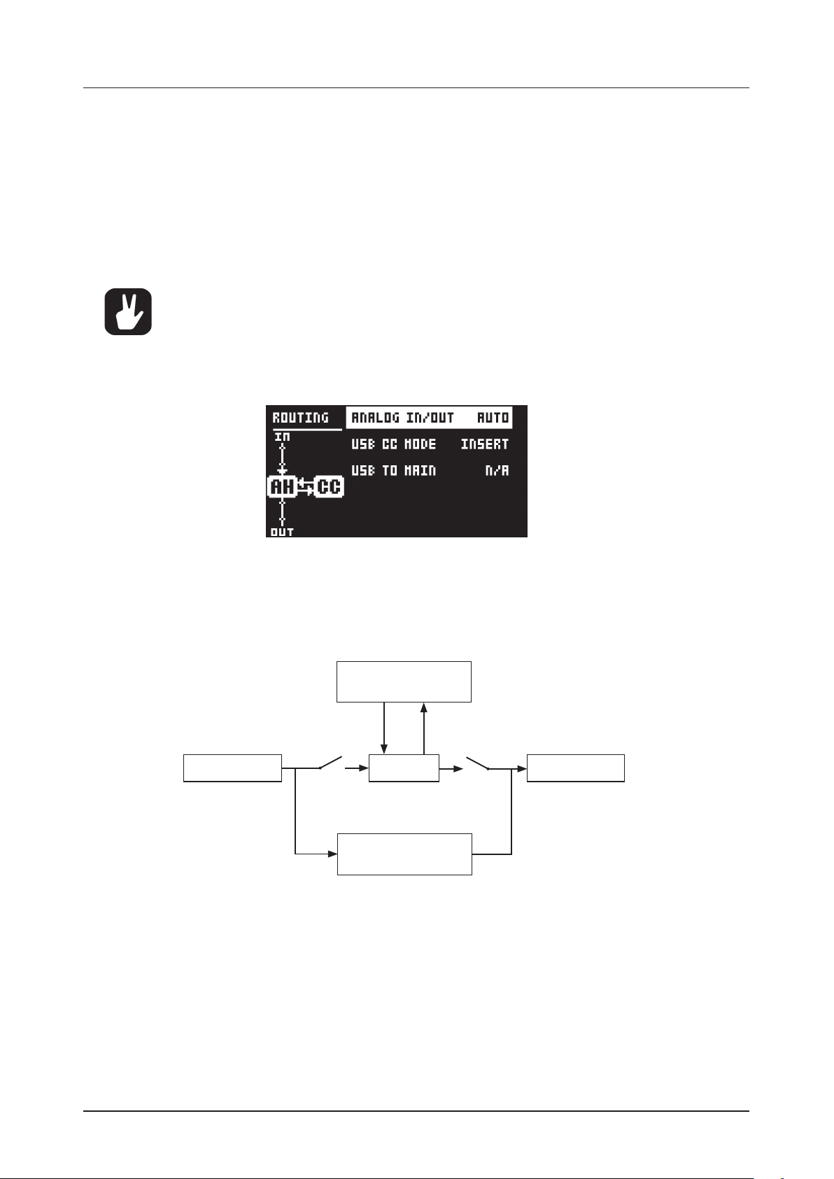
. AUDIO ROUTING........................................................................... 19
6.5.1 ANALOG IN/OUT (IN OVERBRIDGE MODE) ................................................19
6.5.2 ANALOG IN/OUT (IN USB AUDIO/MIDI MODE) .............................................20
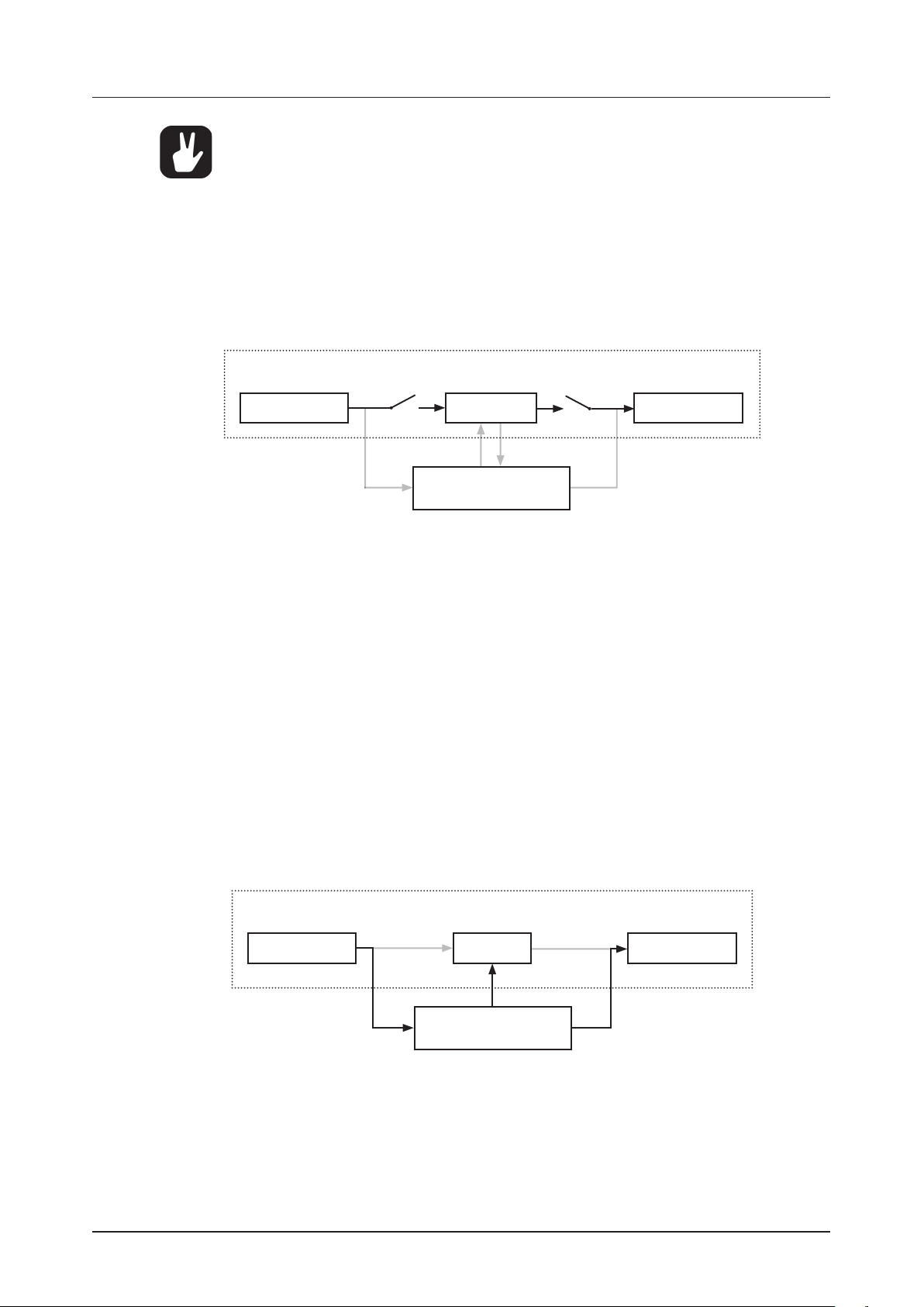
6.5.3 USB CC MODE ...........................................................................20
6.5.4 USB TO MAIN ............................................................................21
6.6 MIDI CONFIG .............................................................................. 21
6.6.1 SYNC .....................................................................................21
6.6.2 PORT CONFIG ...........................................................................21
6.6.3 CHANNELS ..............................................................................22
6.7 SYSEX DUMP ..............................................................................22
6.7.1 SYSEX SEND..............................................................................23
6.7.2 SYSEX RECEIVE ..........................................................................23
. SYSTEM...................................................................................23
6.8.1 USB CONFIG..............................................................................23
6.8.2 OS UPGRADE ............................................................................24
6.8.3 CALIBRATION ............................................................................24
. PARAMETER PAGES. . . . . . . . . . . . . . . . . . . . . . . . . . . . . . . . . . . . . . . . . . . . . . . . . . . . . . . . . . . . . . . . . . . . . . . . . . . . . 25
7.1 FLOW ......................................................................................25
7.1.1 CHANGING THE ORDER OF THE FX BLOCKS ..............................................25
7.1.2 SETTING THE DRY/WET MIX OF THE FX BLOCKS .........................................25
7.1.3 BYPASSING/ACTIVATING AN FX BLOCK ...................................................25
. HEAT......................................................................................26
7.2.1 AMP ......................................................................................26
.. FILTER 1/ ...............................................................................26
7.2.3 FILTER 2/2 ...............................................................................26
7.2.4 GATE.....................................................................................27
. FX .........................................................................................28
7.3.1 BITS ......................................................................................28
7.3.2 WARBLE PAGE 1 ..........................................................................28
7.3.3 WARBLE PAGE 2 .........................................................................28
7.3.4 COMPRESSOR PAGE 1....................................................................28
7.3.5 COMPRESSOR PAGE 2 ...................................................................29
7.3.6 BASS FOCUS.............................................................................29
7.3.7 CHORUS .................................................................................30
7.3.8 DELAY PAGE 1 ............................................................................30
7.3.9 DELAY PAGE 2. . . . . . . . . . . . . . . . . . . . . . . . . . . . . . . . . . . . . . . . . . . . . . . . . . . . . . . . . . . . . . . . . . . . . . . . . . . . 31
7.3.10 REVERB PAGE 1..........................................................................32
7.3.11 REVERB PAGE 2..........................................................................32
. MOD.......................................................................................32
7.4.1 ENV PAGE 1 ...............................................................................32
7.4.2 ENV PAGE 2 ..............................................................................34
7.4.3 LFO1 PAGE 1..............................................................................35
7.4.4 LFO1 PAGE 2 .............................................................................35
7.4.5 LFO2 PAGE 1 .............................................................................36
7.4.6 LFO2 PAGE 2 .............................................................................36
7.4.7 LFO3 PAGE 1 .............................................................................36
7.4.8 LFO3 PAGE 2 .............................................................................36
7.4.9 MATRIX ..................................................................................36

TABLE OF CONTENTS
6
. TIPS & TRICKS ...................................................................................37
. ADDING SATURATION TO THE HIGH REGISTER .............................................37
. ANALOG PSEUDO-COMPRESSION .........................................................37
8.3 STEREO PHASER EFFECT .................................................................38
9. STARTUP MENU .................................................................................39
9.1 TEST MODE ................................................................................39
9.2 EMPTY RESET.............................................................................39
9.3 FACTORY RESET ..........................................................................39
9.4 OS UPGRADE..............................................................................39
. TECHNICAL INFORMATION ...................................................................40
. CREDITS AND CONTACT INFORMATION.....................................................40
APPENDIX A: MIDI.................................................................................. 41
APPENDIX B: MODULATION SOURCES AND DESTINATIONS ................................44
INDEX................................................................................................46

1. INTRODUCTION
7
. INTRODUCTION
Thank you for purchasing Analog Heat +FX. In this third incarnation of Analog Heat, it is the ultimate tool to
create your signature sound. On top of its powerful analog distortion circuits, filter, and EQ, we’ve added a
new layer of digital eects. Using the newly designed graphical user interface, you can freely arrange the
eect chain and choose the order of the FX blocks. Then, use the expanded internal and external modula-
tion capabilities to set it all in motion.
There are many new additions to explore, taking Analog Heat‘s palette of color and destruction to the next
level. Some will even do the opposite and help you keep signals controlled and present in the mix.
All these elements come together to create a box that looks familiar but, at the same time, is much more
than the sum of its parts. Let the sound be your canvas!
- The Elektron Team
. CONVENTIONS IN THIS MANUAL
We have used the following conventions throughout the manual:
• KEY NAMES
Written in uppercase, bold style and within brackets. For example, the key labeled “YES” is called [YES].
• KNOBS
Written in uppercase, bold, italic letters. For example, the knob “NAVIGATION” is called NAVIGATION.
• LED INDICATORS
Written in uppercase letters with angle brackets. For example, the filter type LEDs are called:
<FILTER TYPE>.
• MENU NAMES
Written in uppercase letters. For example, the SETTINGS menu.
• PARAMETER NAMES, MENU OPTIONS
Written in uppercase bold letters for parameter names and certain menu options where you can make
settings or perform actions. For example, ATTACK.
• PARAMETER SETTING ALTERNATIVES
Written in uppercase letters. For example, OFF.
• SCREEN MESSAGES
Written in uppercase letters with quotation marks. For example, “INPUT LEVEL TOO HIGH!”
The manual uses the following symbols:
Important information that you should pay attention to.
A tip that makes it easier for you to interact with Analog Heat +FX.
Analog Heat +FX User Manual. This manual is copyright © 2023 Elektron Music Machines MAV AB. All reproduction
without written authorization is strictly prohibited. The information in this manual may change without notice. Elektron’s
product names, logotypes, titles, words or phrases may be registered and protected by Swedish and international law.
All other brand or product names are trademarks or registered trademarks of their respective holders. This manual for
Analog Heat +FX OS version 1.00 was last updated May 10, 2023.

2. PANEL LAYOUT AND CONNECTIONS
8
. PANEL LAYOUT AND CONNECTIONS
. FRONT PANEL CONTROLS
1 2 3 54 6 7
8
9
10
11
12
131415161718
19
21
20
1. [FLOW] accesses the FLOW parameter page where you can change the order of the FX blocks in the
signal path, activate/deactivate each FX block. You can also set the dry/wet mix of each eect block.
2. [HEAT] accesses the AMP, FILTER, and GATE parameter pages where you, among other things, can
select filter types and adjust the equalizer.
3. [FX] accesses the parameter pages for the digital eects.
4. [MOD] accesses the ENV parameter pages where you adjust the settings for the envelope generator/
envelope follower and the LFO parameter pages. Here you also find the Mod matrix.
5. [SETTINGS] accesses the SETTINGS menu. Contains both global settings and preset settings.
6. Screen.
7. NAVIGATION is used for navigating menus, scrolling through lists and selecting options.
8. [NO] is used for exiting the current menu, backing to a higher level menu and negating.
9. [YES] is used for entering sub-menus, selecting and confirming.
10. DATA ENTRY knobs. Used to set parameter values.
11. LOW and HIGH adjust the amount of low-end and high-end frequency gain or attenuation of the eect
circuit in the Heat block.
12. <FILTER TYPE> LEDs that indicate the current type of filter and also if the filter is on or not.
13. RESONANCE sets the resonance of the Heat block’s filter.
14. [FILTER TYPE] selects between the dierent filter types in the Heat block. Pressing both keys at the
same time toggles the filter on and o.
15. FREQUENCY sets the cuto frequency of the Heat block’s filter.
16. MIX sets the balance between the Heat block’s unprocessed (dry) signal and the processed (wet) signal.
17. LEVEL sets the level of the processed (wet) signal in the Heat block.
18. DRIVE controls the amount of drive in the Heat block. This parameter increases the eect of the select-
ed circuit type.
19. CIRCUIT SELECTOR chooses between the eight dierent types of eect circuits in the Heat block.
20.[ACTIVE] toggles the eect between active (LED on) and bypassed.
21. MAIN VOLUME sets the main volume for the L/R and Headphones audio outputs.

2. PANEL LAYOUT AND CONNECTIONS
9
. REAR PANEL CONNECTIONS
1 2 3 4 5 6 7 8 9 10
1. POWER, Switch for turning the unit on and o.
2. DC IN, Input for power supply. Use the included PSU-3b power adapter connected to
a power outlet.
3. USB, For connecting the unit to a computer. Used for MIDI control or Overbridge.
Connect to a computer host using the included A to B USB 2.0 connector cable.
4. MIDI THRU/SYNC B, Forwards data from MIDI IN. Can also be configured to send DIN sync to legacy
instruments. Use a standard MIDI cable to connect another MIDI unit in the chain.
5. MIDI OUT/SYNC A, MIDI data output. Can also be configured to send DIN sync to legacy instruments.
Use a standard MIDI cable to connect to MIDI In of an external MIDI unit.
6. MIDI IN, MIDI data input. Use a standard MIDI cable to connect to MIDI Out of an
external MIDI unit.
7. CONTROL IN A/B Inputs for an expression pedal, footswitch, or CV. Use 1/4” mono phone plug for
CV signals.
8. INPUT L (mono)/R, Audio inputs. Use either 1/4” mono phone plug (unbalanced
connection) or 1/4” (Tip/Ring/Sleeve) phone plug (balanced connection).
9. OUTPUT L/R, Main audio outputs. Use either 1/4” mono phone plug (unbalanced
connection) or 1/4” (Tip/Ring/Sleeve) phone plug (balanced connection).
10. HEADPHONES, Audio output for stereo headphones. Use 1/4” (Tip/Ring/Sleeve)
phone plug.

3. FIRST STEPS WITH THE ANALOG HEAT +FX
10
. FIRST STEPS WITH THE ANALOG HEAT +FX
. CONNECTING THE UNIT
Make sure you place the Analog Heat +FX on a stable support, such as a sturdy table with sucient cable
space. Before you start connecting the Analog Heat +FX to other units, make sure all units are switched o.
1. Plug the supplied DC adapter to a power outlet and connect the small plug to the 12 V DC connector
of the Analog Heat +FX unit.
2. Connect the audio source to INPUT L/R.
3. Connect the OUTPUT L/R from the Analog Heat +FX to your mixer or amplifier.
4. To process sound or control the Analog Heat +FX from a computer, connect a USB cable between the
computer and the USB connector of the Analog Heat +FX. You must also download and install the
Overbridge Suite to perform these actions.
5. If you want to use MIDI to control the Analog Heat +FX, connect the MIDI OUT port of the device you
wish to send data from to the MIDI IN port of the Analog Heat +FX. The MIDI THRU port duplicates
the data arriving at the MIDI IN port, so you can use it for chaining MIDI units together.
6. Switch on all units. Press the power switch located at the back of the Analog Heat +FX to switch it on.
. SETTING THE INPUT SENSITIVITY LEVEL
To make sure the Analog Heat +FX distorts as intended it is essential to set the audio input sensitivity so
that it matches the level of the sound source. (Note that the settings made here only aects the analog
input and not the digital input from Overbridge.) Use the audio input meter on the screen to monitor your
audio input level and follow these steps to set the input sensitivity level:
1. Connect your sound source to the IN L/R inputs of the Analog Heat +FX and make sure that the vol-
ume of the sound source is as loud as possible.
2. Press [SETTINGS] and the select INPUT SENSITIVITY. Keep an eye on the audio input meter and
change the input sensitivity until you find a setting where the bar reaches the vertical line but without
clipping. The message “INPUT LEVEL TOO HIGH” is displayed on the screen when the input level is
too high, and clipping occurs.
Optimal input level.
Too high input level.
3. Adjust the level at the sound source if needed.
. SETUP EXAMPLES
The Analog Heat +FX is very well suited for use in both an analog setup and in a more digital environment.
Here are a couple of examples of how you can use the Analog Heat +FX. For more information about how
to set up Analog Heat +FX in dierent configurations, please see “6.5 AUDIO ROUTING” on page 19.

3. FIRST STEPS WITH THE ANALOG HEAT +FX
11
3.3.1 ANALOG HEAT +FX AS AN EXTERNAL EFFECT
In this example, the Analog Heat +FX is used as an external eect to add color to the Elektron Octatrack
before the signal reaches the mixer.
3.3.2 ANALOG HEAT +FX AS A VST/AU/AAX PLUGIN USING OVERBRIDGE
Analog Heat +FX can also be used together with Overbridge to allow you to use the Analog Heat +FX as
a plug-in for analog and digital processing sound processing in your DAW.
USB
3.3.3 ANALOG HEAT +FX AS A SOUND CARD
Analog Heat +FX also functions as a 2 in/2 out sound card for your computer and can be used for both
recording and monitoring audio. At the same time you can, via Overbridge, use the eect to process
another set of audio signals.
USB

4. SIGNAL FLOW
12
. SIGNAL FLOW
The illustrations below show the signal flows of the Analog Heat +FX and illustrates how the dierent com-
ponents interact with each other.
. AUDIO SIGNAL FLOW
This illustration shows the general flow of audio through the Analog Heat +FX. The complete signal chain is
in stereo.
In L/R
Input
Sensitivity
FX
block
Main
Volume
Out L/R
Head-
phones
Circuit
Dirt
Drive
Multi-mode
Filter Equalizer
Overbridge or Class compliant USB audio host
Bypass
Gate
Wet level Dry/Wet
Mix
Heat
block
FX
block
. MODULATION SIGNAL FLOW
This illustration shows the flow of how modulation signals are generated and routed through the
Analog Heat +FX.
In L/R
Input
Sensitivity
Bandpass
Filter
Envelope
Follower
Gain
Filter
Modulation
Modulation
Destination
Compar-
ator
LFO Modulation
Destination
Modulation
Destination
Trig
Filter
Modulation
Filter
Modulation
Envelope
Generator
Over-
bridge

5. INTERACTING WITH THE ANALOG HEAT +FX
13
. INTERACTING WITH THE ANALOG HEAT +FX
. PRESETS
The Analog Heat +FX has 512 preset slots divided into four banks where you can store your presets. Preset
slot ... is an INIT preset with default values. Note that, when switching o the power on your Heat, any
changes to the currently active preset will be lost unless the preset is first saved. For more information,
please see “5.12 SCREEN INFORMATION” on page 15.
5.1.1 LOADING A PRESET
1. Press the [FLOW] and [HEAT] keys simultaneously to open the preset list
2. Press a DATA ENTRY knob to select bank A–D (if you want to load a preset from another bank).
3. Turn NAVIGATION to select a preset.
4. Press NAVIGATION or [YES] to load the preset.
5.1.2 SAVING A PRESET
1. Press and hold the [FLOW] and [HEAT] keys simultaneously for two seconds to open the preset
list. The selected preset starts to blink to illustrate that you are about to overwrite a preset position.
2. Press a DATA ENTRY knob to select bank A–D if you want to save the preset to dierent bank.
3. Turn NAVIGATION to select the preset slot to where you want to save your sound and then press
[YES].
4. (Optional) Turn NAVIGATION to the character you wish to edit. Press and hold [SETTINGS] and
then turn NAVIGATION to move the cursor to the desired character and select it by releasing [SET-
TINGS]. To delete a character, turn NAVIGATION to move the cursor to highlight the character after
the one you wish to delete, then press and hold [SETTINGS] and press [NO] twice.
5. Press [YES] to save the preset.
. ACTIVE
When [ACTIVE] is toggled ON, the Analog Heat +FX aects the incoming signal. The active mode is tog-
gled on and o by pressing [ACTIVE]. A lit [ACTIVE] key indicates that the device is active. You can also
use a Footswitch to toggle the active mode. For more information, please see “6.4 CONTROL IN” on page
18. You also have the option to set if you want the Analog Heat +FX to start as active or not when you
turn it on. For more information, please see “6.3.3 ACTIVE AT START” on page 18. Press [ACTIVE] again
to toggle the device OFF to bypass the eect.
. EFFECT CIRCUITS
You can use the CIRCUIT SELECTOR to choose between 8 dierent types of eect circuits for a wide vari-
ety of drive and distortion sounds.
• CLEAN BOOST
Makes the signal louder. When fully driven, it sounds similar to overdriving old mixers. Use for minimal
distortion or when you only want to use the filter and EQ.
• SATURATION
This circuit is reminiscent of classic tape saturation. Woolly and warm.
• ENHANCEMENT
Adding tube-like glow and sheen to a track or loop.
• MID DRIVE
Mid-range focused overdrive with a solid and distinct body.
• ROUGH CRUNCH
Gritty, worn and gnarly character. Full of flavor.
• CLASSIC DIST
Pleasantly distorts upper mid-range frequencies. Ideal for acid bass lines.
• ROUND FUZZ
Adds a lot of harmonics and alters the signal in interesting and often unpredictable ways.
• HIGH GAIN
Probably the most aggressive of all the circuits. Very maxed out!

5. INTERACTING WITH THE ANALOG HEAT +FX
14
. FILTER TYPES
Change the type of the filter by pressing one of the two [FILTER TYPE] keys. You can also press the two
[FILTER TYPE] keys simultaneously to toggle the filter on/o. It is possible to change the filter type even if
the filter is turned o.
There are seven dierent analog filter types in the Analog Heat +FX to help to shape the sound.
• LOW PASS 2 (two-pole, 12 dB per octave)
• LOW PASS 1 (one-pole, 6 dB per octave)
• BAND PASS
• HIGH PASS 1 (one-pole, 6 dB per octave)
• HIGH PASS 2 (two-pole, 12 dB per octave)
• BAND STOP (NOTCH)
• PEAK
. EQUALIZER
LOW and HIGH adjust the amount of low-end and high-end frequency gain or attenuation of the eect
circuit. Each character circuit comes with its tailor-made equalizer characteristics. For more information,
please see “4.1 AUDIO SIGNAL FLOW” on page 12.
. DRIVE
DRIVE sets the gain level in the eect circuit. A higher setting increases the eect of the selected circuit type,
typically resulting in more distortion. For more information, please see “4.1 AUDIO SIGNAL FLOW” on page
12.
. LEVEL
LEVEL sets the level of the signal coming from the eect. It is applied before the dry/wet mix set by MIX. It
is used to match the level of the dry signal for easy mixing of the two. For more information, please see “4.1
AUDIO SIGNAL FLOW” on page 12.
. MIX
MIX sets the mix between the clean (dry) signal and the signal that is aected by the eect (wet). For more
information, please see “4.1 AUDIO SIGNAL FLOW” on page 12.
. SETTINGS MENU
Press [SETTINGS] to access the SETTINGS menu.
Scroll through the list of settings by using the NAVIGATION knob. Open a highlighted menu by pressing the
NAVIGATION knob or [YES]. To change the settings in the menus, first press, and then turn the NAVIGA-
TION knob. For more information, please see “6. THE SETTINGS MENU” on page 17.
. PARAMETER PAGES
Press a [PARAMETER] page key to access the corresponding parameter pages [FLOW], [HEAT], [FX],
and [MOD]. There are usually several parameter pages associated with each key. You access these pages
by turning the NAVIGATION knob.. For more information, please see “7. PARAMETER PAGES” on page 25.
. PARAMETER EDITING
The four DATA ENTRY knobs are used to set the parameter values that you see on the screen. (Some
parameters also have dedicated knobs on the panel.) The physical location of the knobs on the front panel
corresponds to the layout of the parameters on the screen.

5. INTERACTING WITH THE ANALOG HEAT +FX
15
• Press down and turn the DATA ENTRY to adjust the parameters in larger increments.
• Press [SETTINGS] + turn DATA ENTRY knob to quantize the parameter value to integers.
• Press [NO] +DATA ENTRY knob to reset the parameter to the default value.
• Press [NO] +[PARAMETER] page key to reset the selected parameter group to default values.
• Use the [NO] key to exit an active menu, back to a higher level menu and to negate.
. SCREEN INFORMATION
Parameter page Audio input meter Trigger icon
Current Parameter
page graphical info
Current Parameter
page parameters
• When on a parameter page, the title bar shows the name of the active parameter page. This text is re-
placed by parameter names when turning the DATA ENTRY knobs or the dedicated controllers.
• The Audio Input meter displays the level of the incoming audio.
• The Trigger icon shows that the Envelope Follower, an external gate signal or manual triggering has
generated a trigger event.
• The graphical information varies depending on the current PARAMETER page.
• The PARAMETER page parameters show what the DATA ENTRY knobs control and their current param-
eter values.
The Analog Heat +FX features a screen saver that dims the screen after 5 minutes of inactivi-
ty and turns o the screen after 60 minutes. Press any key or move any controller to wake up
the screen.
5.13 TEMPO
Press the [FX] and [MOD] keys simultaneously to open the TEMPO menu where you can change the BPM
setting. Use the two leftmost DATA ENTRY knobs to change tempo. The first sets the coarse BPM and the
second sets the decimal. Pressing the knob while turning it changes the tempo two BPM at a time. You can
also choose between a global tempo or use a separate tempo for every pattern.
To tap a tempo setting, tap the [YES] key in a steady rhythm. The average tempo of the taps calculates
after four consecutive taps. If you continue tapping, the average tempo keeps updating.
. OVERBRIDGE
The Overbridge software suite enables a tight integration between the Analog Heat +FX and a computer
DAW software.
When using Overbridge, the user interface for the Analog Heat +FX presents itself as a plug-in window in
your DAW. Access, edit and automate parameters for sound shaping on screen. Always find your device
preset parameters in the same state as you left them when you return to your DAW project, with the useful
total recall functionality.
Read more about Overbridge use and availability on the Elektron website.

5. INTERACTING WITH THE ANALOG HEAT +FX
16
5.15 CLASS COMPLIANT DEVICE
The Analog Heat +FX is a class compliant device (also known as plug-and-play). It means it does not require
any extra drivers to connect to your Windows or macOS computer, or your iOS device.
The Analog Heat +FX can, therefore, stream audio and MIDI directly over USB to and from supported
computers/phones/tablets. It opens up several exciting possibilities of what you can do with your device,
for example, record audio from your device directly over USB in your DAW. For more information, please see
“6.8.1 USB CONFIG” on page 23 and “6.5.3 USB CC MODE” on page 20
5.16 BACKING UP THE ANALOG HEAT +FX
It is always recommended to make regular backups of your data. Backups are also a convenient way to
share your presets with other users. To make backups and transfer files to and from your Elektron device,
you should use Transfer, a free application that you can download from the Elektron site https://www.elek-
tron.se/support. The application is available for both Windows and macOS.
5.16.1 BACKING UP PRESETS
You can backup up your presets from your Elektron device to a computer. Here is the general procedure
for how to back up your device:
1. Connect the Elektron device to the computer via USB.
2. Open the Transfer application on your computer, and then select the USB MIDI port(s) for your
device on the CONNECTION page, and then click “CONNECT” next to your device under AVAILABLE
DEVICES.
3. In Transfer, click the EXPLORE tab to open the EXPLORE page.
4. On the EXPLORE page top left side of the drop-down menu, make sure “MY COMPUTER” is selected.
5. On the top right side, in the drop-down menu, select the type of file you want to transfer.
6. In the window on the right, navigate to the files or folders you want to transfer
7. Drag and drop the files or folders to your preferred location under “MY COMPUTER.”
5.16.2 TRANSFERRING BACKED UP FILES TO YOUR ELEKTRON DEVICE
Use the EXPLORE page in Transfer to transfer previously backed up files to your Elektron device from a
computer.
1. Connect the Elektron device to the computer via USB.
2. Open the Transfer application on your computer and then select the USB MIDI port(s) for your device on
the Transfer CONNECTION page. Click “CONNECT” next to your device under AVAILABLE DEVICES.
3. In Transfer, click the EXPLORE tab to open the EXPLORE page.
4. On the top right side, in the drop-down menu, select the type of file you want to transfer.
5. On the top left side in the drop-down menu, make sure “MY COMPUTER” is selected.
6. Under “MY COMPUTER,” navigate to the files or folders you want to transfer.
7. Drag and drop the files or folders to your preferred location on your device.
8. Depending on what file type you send, you might encounter pop-up windows asking you to decide
what files you want to send and how you want to organize them.

6. THE SETTINGS MENU
17
. THE SETTINGS MENU
Here follows a description of all the parameters that are in the SETTINGS menu. You access the SETTINGS
menu by pressing the [SETTINGS] key. Scroll through the list of settings by using the NAVIGATION knob.
Open a highlighted menu by pressing the NAVIGATION knob or [YES]. To change the settings in the menus,
first press and then turn the NAVIGATION knob.
. PRESET CONFIG
6.1.1 ANALOG MODE
Disables the digital FX blocks, which makes the Analog Heat +FX audio path analog when this option is
enabled.
6.1.2 VOLUME
Preset Volume sets the overall level of the preset. This parameters is also a modulation destination.
. INPUT SENSITIVITY
Sets the audio input level to fit the audio level sent to the eect via the IN L/R inputs. It is important to set
this level correctly to get the best sound from your Analog Heat +FX. There are four dierent settings for
the input sensitivity: LOW, MID, HIGH & MAX. Low is the most silent, Max is the loudest. For more informa-
tion, please see “3.2 SETTING THE INPUT SENSITIVITY LEVEL” on page 10.
• LOW (Maximum input level 10.5 V, peak to peak)
• MID (Maximum input level 5.3 V, peak to peak)
• HIGH (Maximum input level 2.5 V, peak to peak)
• MAX (Maximum input level 1.2 V, peak to peak)

6. THE SETTINGS MENU
18
. OPTIONS
6.3.1 PAGE MENU
Will, when selected, display a popup parameter page menu when turning NAVIGATION on a parameter
page.
6.3.2 FX PAGE ORDER
Sets the order in which the FX parameter pages are displayed.
• FLOW follows the order of how the FX blocks are arranged on the FLOW page.
• ALPHA sorts the pages in alphabetical order .
• FIXED the order is fixed based on the order on the INIT preset.
6.3.3 ACTIVE AT START
Sets if Analog Heat +FX is in Active Mode or not when it is turned on.
6.3.4 KNOB MODE
Sets how the knobs on the panel aect the parameters. When you load a preset, the knobs positions
typically don’t match their parameter values.
• JUMP immediately sets the value to the current knob position.
• In CATCH mode, turning the knob do not change the parameter value until the knob position match-
es the presets stored value.
You can see the current value of the parameter in the screens title bar while you turn the knob.
. CONTROL IN
6.4.1 CONTROL IN A
• CONTROL MODE
Sets the port mode to adjust to dierent kinds of input signals. There are four modes: CV (Control
Voltage), EXPR (Expression Pedal), FOOTSW (Footswitch) and OFF.
• CV ZERO LEVEL (Available when mode is set to CV.)
Sets the Volt level at which CV modulation amount is zero. A control input level equal to this setting
corresponds to zero modulation. (. V–+5.50 V).
• CV MAX LEVEL (Available when mode is set to CV.)
Sets the Volt level at which CV modulation amount is max. A control input level equal to this setting
corresponds to full modulation. (. V–+5.50 V).
• EXPRESSION LEARN (Available when mode is set to EXPR.)
Sets the highest and lowest limit of the control input level. When in this setting, connect the Expression
pedal to CONTROL IN A/B. Press YES and then move the expression pedal first to max and then to
min position. Press YES to save settings.
• REVERSE DIRECTION (Available when mode is set to EXPR.)
Reverses the direction of how the Expression pedal sends control input signals.
• FOOTSW DEST (Available when mode is set to FOOTSW.)

6. THE SETTINGS MENU
19
Sets the destination of the control input from the Footswitch. The options are: TEMPO, ACTIVE,
PRESET +, PRESET , ENV TRIG
• FOOTSWITCH LEARN (Available when mode is set to FOOTSW.)
Sets the high and low limit of the control input level. When in this setting, connect the Footswitch
pedal to CONTROL IN A/B. Press YES and then press the Footswitch pedal a couple of times.
Press YES to save settings.
• REVERSE DIRECTION (Available when mode is set to FOOTSW.)
Reverses the direction of how the Footswitch pedal sends control input signals.
6.4.2 CONTROL IN B
The available settings are the same as for CONTROL IN A.
If you set CONTROL MODE to FOOTSW you can send a gate signal to the Control In
inputs to trigger the envelope generator. For more information, please see “7.4.1 ENV PAGE
1” on page 32.
. AUDIO ROUTING
These settings are stored in the global settings and are not part of the preset.
6.5.1 ANALOG IN/OUT (IN OVERBRIDGE MODE)
Sets if the signal from the analog inputs (INPUT L/R) is routed to the FX blocks or not. It also sets if the
signal from the eect is routed to analog outputs (OUTPUT L/R and HEADPHONES) or not. These are
the settings if Overbridge mode is chosen in the USB CONFIG menu. For more information, please see
“6.8.1 USB CONFIG” on page 23.
OVERBRIDGE
PLUGIN
AH
OVERBRIDGE
AUDIO INTERFACE
ANALOG IN ANALOG OUT
IN OUT
Analog Input L/R Analog Output L/R
FX Return L/RFX Send L/R
Analog Heat +FX supports 4 channels of audio. Audio from Analog Input is routed to the analog in-, and
outputs, and can optionally also be routed through the FX blocks. FX Send L/R is always routed to the
eect.
• AUTO In AUTO mode, Analog Heat +FX automatically detects if the Overbridge plugin is running
or not. With Overbridge running, the Analog In is not routed through the eect to the Analog Out.
(Same as OFF setting.) If Overbridge is not running, the signal from Analog In is routed through the
FX to the Analog Out. (Same as the IN+OUT setting.)
• IN+OUT Both Analog In and Analog Out are routed to the FX.
• IN Routes the signal from Analog In to the FX.
• OUT Routes the signal from the eect to Analog Out.
• OFF Neither Analog In nor Analog Out are routed to the FX.

6. THE SETTINGS MENU
20
You can use the Analog Heat +FX as a regular audio interface and let signals pass in and
out unaected by the eect. At the same time, you can, via Overbridge, also use the eect
to process another set of audio signals.
AUTO mode is suitable for most use cases. It lets the Analog Heat +FX function both as a
standalone eect and together with Overbridge as a plugin, while still retaining its func-
tionality as a sound card.
6.5.2 ANALOG IN/OUT (IN USB AUDIO/MIDI MODE)
Sets if the signal from the analog inputs (INPUT L/R) is routed to the eect or not. It also sets if the
signal from the FX is routed to analog outputs (OUTPUT L/R and HEADPHONES) or not. These are the
settings if USB AUDIO+MIDI mode is chosen in the USB CONFIG menu. For more information, please
see “6.8.1 USB CONFIG” on page 23.
FX BLOCKS
CLASS COMPLIANT
USB AUDIO HOST
ANALOG IN ANALOG OUT
IN OUT
Analog Heat +FX
• AUTO In AUTO mode, Analog Heat +FX automatically detects if a class compliant USB audio host
(computer, smartphone, etc.) is connected or not. If no USB audio host is connected, the signal is
routed from Analog In through the FX to the Analog Out. (Same as the IN+OUT setting.) With the
USB audio host connected, the audio routing in AUTO mode depends on which option is selected
by the USB CC MODE parameter:
INSERT sets ANALOG IN/OUT to IN+OUT.
PRE sets ANALOG IN/OUT to OUT.
POST sets ANALOG IN/OUT to IN.
BYPASS sets ANALOG IN/OUT to OFF.
• IN+OUT Both Analog In and Analog Out are routed to the FX.
• IN Routes the signal from Analog In to the FX.
• OUT Routes the signal from the eect to Analog Out.
• OFF Neither Analog In nor Analog Out are routed to the FX.
6.5.3 USB CC MODE
Sets how and where, in the signal chain, the signal between the Analog Heat +FX and the class com-
pliant USB audio host (computer, smartphone etc.) is routed. This parameter is only available if USB
AUDIO+MIDI mode is chosen in the USB CONFIG menu. For more information, please see “6.8.1 USB
CONFIG” on page 23.
FX
CLASS COMPLIANT
USB AUDIO HOST
ANALOG IN ANALOG OUT
Analog Heat +FX
USB TO MAIN
INSERT Routes the audio bi-directionally over USB between the FX (distortion circuit, EQ, and filter) and
the USB audio host.
• PRE Routes the audio from Analog In to the USB audio host and then back to the FX.
• POST Routes the audio from the FX to the USB audio host and then to the Analog Out.
• BYPASS Routes the audio from Analog In to the USB audio host and then to Analog Out without
being aected by the FX.
Other manuals for Analog Heat +FX
1
Table of contents
Other Elektron Recording Equipment manuals

Elektron
Elektron Analog Heat MKII User manual

Elektron
Elektron Octatrack DPS-1 User manual

Elektron
Elektron analog drive User manual

Elektron
Elektron Analog Heat +FX User manual

Elektron
Elektron Analog Heat MKII User manual

Elektron
Elektron MonoMachine SFX-6 Installation and operating instructions

Elektron
Elektron Analog heat User manual

Elektron
Elektron Octatrack User manual