ElektroPhysik MiniTest 600 User manual

Bedienungsanleitung MiniTest 600 Version 2.4 Englisch

© 03/2002 B10-N
Subject to change without notice.
ElektroPhysik Dr. Steingroever GmbH & Co. KG
Pasteurstr. 15
50735 Cologne
Germany
Tel.: +49 221 752040
Fax.: +49 221 7520467
web: www.elektrophysik.com
mail: [email protected]

MiniTest 600
Technical Reference and
Operating Manual
Advancing with Technology ElektroPhysik

ElektroPhysik i
Table of Contents
Table of Contents
1. General Information .................................. 1
1.1 Applications................................................1
1.2 Description of the gauge...........................3
1.3 Equipment...................................................5
1.4 Probe construction ....................................5
2. Preparing the MiniTest 600 gauges ........ 6
2.1 Checking the power supply ......................6
2.2 Replacing the batteries .............................7
2.3 Start-up functions ......................................8
2.3.1 Total reset ....................................................9
2.3.2 LCD segment test........................................9
2.4 Basic gauge settings .............................. 10
2.4.1 Switching between short-term and
long-term modes ...................................... 12
2.4.2 KEYLOCK Function for ZERO- and
CAL-keys (locks calibration keys)............. 12
2.4.3 Activating/deactivating the
LC display light (optional) ......................... 13
2.4.4 Select a measuring unit
‘metric’ - ’inch’ (imperial) ........................... 13

ii ElektroPhysik
Table of Contents
3. Calibration and measurement ............... 14
3.1 General remarks on calibration ............. 14
3.1.1 Methods of calibration .............................. 14
3.1.2 Saving calibration values.......................... 15
3.1.3 Example of calibration .............................. 16
3.1.4 The effects of substrate thickness ............ 17
3.1.5 High-accuracy calibration ......................... 19
3.1.6 Cleaning the measuring point .................. 19
3.1.7 Acoustic signal.......................................... 19
3.1.8 Stabilisation of calibration values. ............ 20
3.2 Points to remember when calibrating ... 20
3.2.1 Activate standard calibration .................... 21
3.2.2 One-point calibration without foil
(zero only)................................................. 22
3.2.3 Two-point calibration
(ZERO with one calibration foil) ................ 24
3.2.4 Calibration and measurement with
MiniTest 600 FN........................................ 27
3.2.5 Calibration and measurement on
shot blasted surfaces................................ 28
3.2.6 Adjusting the basic calibration.................. 31
3.3 General remarks on measurement........ 31

ElektroPhysik iii
Table of Contents
4. Measurement using statistics ............... 32
4.1 Definition of statistical values ............... 33
4.2 Entering a series of measurements
for statistical analysis............................. 34
4.3 Storage capacity overflow ..................... 35
4.4 Display and print-out of the 5
statistical values for a series of
measurements (no single value) ........... 35
5. ‘Delete’ functions .................................... 36
5.1 Deleting the last reading taken.............. 36
5.2 Deleting statistics ................................... 36
7. Interface description............................... 37
8. Accessories ............................................. 38
9. Maintenance............................................. 39
10. Customer service .................................... 39
11. Troubleshooting ...................................... 39
12. Example of how to operate the
MiniTest 600 ............................................. 41
13. Technical Data ......................................... 45

iv ElektroPhysik
Table of Contents
13.1 Technical data (metric system).............. 45
13.2 Technical Data (imperial system) .......... 47

ElektroPhysik 1
1. General Information
1.1 Applications
This compact, handy pocket gauge is designed for
non-destructive, fast and precise coating thickness
measurement. The principal applications lie in the
field of corrosion protection. It is ideal for
manufacturers and their customers, for offices and
specialist advisers, for paint shops and
electroplaters, for the chemical, automobile,
shipbuilding and aircraft industries and for light and
heavy engineering.
The range of applications is indicated by the probes
available.
- F probes work on the magnetic induction
principle and should be used for non-
magnetic coatings such as aluminium,
chrome, copper, zinc, paint and varnish,
enamel, rubber etc., on an iron or steel
substrate; they are also suitable for alloyed
and hardened magnetic steel.
General Information

2 ElektroPhysik
- N probes work on the eddy-current principle
and should be used for insulating coatings
on all non-ferrous metals and on austenitic
stainless steels, e.g. paint, anodising
coatings, ceramics, etc. applied on
aluminium, copper, zinc die-casting, brass,
etc.
- FN probes work on a combination of the
magnetic induction and the eddy-current
principle. One probe only is required for
coating measurement both on ferrous and
non-ferrous metal substrates. When switched
to automatic mode (see 1.2) both principles
are used for coating measurement (the
gauge version MiniTest 600 B is not equipped
with an automatic mode to switch
automatically between the two measuring
principles).
General Information

ElektroPhysik 3
1.2 Description of the gauge
Measured values and user information are shown
on a large, easy-to-read LC display. A display back
light (optional) ensures easy reading of screen data
in poorly-lit conditions. The gauges’ user-friendly
measuring system permits automatic storage of up
to 9 999 readings in one memory matrix for later
statistical evaluation (statistical evaluation is not
possible with MiniTest 600 B).
Note:
- MiniTest 600 FN is equipped with a manual
as well as with an automatic mode.
- The manual mode serves to activate either
the magnetic induction principle (F) or the
eddy-current principle (N) by means of the
arrow keys.
- Owing to a special evaluation algorithm the
correct coating thickness is always shown
after corresponding calibration when the
Description of the gauge

4 ElektroPhysik
gauge is switched to automatic mode working
on ferrous steel as well as on non-ferrous
metal (the gauge version MiniTest 600 B is
not equipped with an automatic mode).
- The statistical values measured on steel or
on nonferrous metal (n, x, s, max, min) are
stored in separate memories.
- All MiniTest 600 gauges are suitable for
particular fields of application, e.g. for
measurement on special geometries. After
storage of the corresponding parameters the
gauge automatically takes them into
consideration.
The portable data printer MiniPrint 4100 allows
immediate printing of measured values and subse-
quent printing of the 5 statistical values. The data
printer is connected to the MiniTest by means of a
cable and is instantly ready for use (printing and
statistical evaluation are not possible with MiniTest
600 B).
Description of the gauge

ElektroPhysik 5
1.3 Equipment
Standard gauge including probe(s), 2 alkaline
batteries, zero standards, calibration foils and
operating instructions.
1.4 Probe construction
All probe systems are spring-mounted in the probe
sleeve. This ensures safe and stable positioning of
the probe and even contact pressure. A V-groove in
the sleeve of the probes facilitates reliable readings
on small cylindrical parts.
The probe should be held by the spring-mounted
sleeve.The hemispherical tip is made of hard and
durable material.
Equipment and probe construction

6 ElektroPhysik
2. Preparing the MiniTest 600
gauges
2.1 Checking the power supply
1. 2 x 1.5 volt alkaline-battery or
2 x 1.2 volt rechargeable battery
2. Check battery condition by pressing ON .
- no LC display:
battery missing or batteries charge too low
to illuminate display
- no BAT display:
batteries is sufficiently charged
- flashing BAT display, gauge switches itself
off after about 1 sec:
replace batteries immediately
Checking the power supply

ElektroPhysik 7
If the BAT display flashes during measurement, the
batteries are running low and should be replaced
before the gauge is switched on again. If not, the LC
display will show the permanent BAT warning and
the gauge will switch itself off after about a second.
Note:
Note that the gauge will not make faulty
measurements even if the voltage is very low.
2.2 Replacing the batteries
1. Place the gauge upside down on a suitable
surface.
2. Push the lid of the battery compartment in
direction of the arrow and raise the lid of the
compartment.
3. Remove batteries.
4. Insert new batteries.
5. Replace the battery compartment lid.
Replacing the batteries

8 ElektroPhysik
Caution:
Make sure that the positive and negative poles are
correctly positioned. If not, all data saved to memory
will be lost.
An interval of more than 10 seconds between
removing the old batteries and inserting the new
one will also result in the loss of data (readings,
calibration values, time and date).
2.3 Start-upfunctions
The MiniTest 600 gauges include a number of
functions that can only be called up or activated
through start-up of the gauge.
Function Key combination
Total reset ZERO + CLEAR + ON
LCD-Test ⇑−key + ON
Set gauge options ZERO + ON
Start-up functions

ElektroPhysik 9
2.3.1 Total reset
A total reset erases all statistical and calibration data
and the gauge will resume the basic MODI-setting
(ZERO - : / 0, see section 2.4).
1. Switch off gauge.
2. Press CLEAR-, ZERO- and ON
simultaneously.
Total reset is confirmed by a long bleep.
2.3.2 LCD segment test
The LCD segment test enables all sections of the
LC display to be inspected and checked.
1. Switch off the gauge.
2. Hold down the ñ-key, press ON and keep
both keys depressed. As long as the arrow
key is depressed, all sections of the LC
display will be shown.
Total reset and LCD segment test

10 ElektroPhysik
2.4 Basic gauge settings
1. Switch off the gauge, hold down the ZERO
key and press ON.
2. Keep both keys pressed until you hear the
signal. The gauge will now display a pair of
numbers: 1:0 or 1:1.
Note:
If you are using a MiniTest 600 FN, use the arrow
keys to activate the F section (ñ) or the N section
(ò) or wait 3 seconds until switching between
sections is performed automatically.
3. Press ZERO to move through each of the
table’s function from 1 to 4. Use the arrow
keys to set the option 0 or 1.
4. Press ZERO again to return to measuring
mode.
Basic gauge settings
ElektroPhysik 11
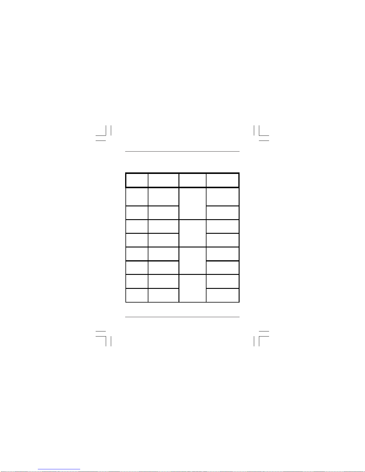
Table of basic settings
Basic gauge settings
Zero-key Arrow-keys↑ ↓ Modi-setting
10wwitch-off
mode short-term
mode
1 long-termmode
2 0 key lock
mode for
ZEROCal
off
1keylock
30displaylight
(option) inactive
1active
4 0 measuring
mode metric/mm
1 imperial/inch

12 ElektroPhysik
2.4.1 Switching between short-term and long-
term modes
The gauge is programd to switch itself off after about
90 seconds of inactivity. This can hinder operations
in certain circumstances. In this case please switch
sto the alternative long-term mode.
To switch the gauge to long-term mode, please refer
to the table of gauge settings in section 2.4.
Adjust to the new mode with the ZERO- and arrow
keys as described.
2.4.2 KEYLOCK Function for ZERO- and CAL-
keys (locks calibration keys)
An accidental recalibration or unintentional offset
input can be prevented by using the KEYLOCK
function.
To activate the KEYLOCK function please refer to
the table of gauge settings in section 2.4. Select
option with the ZERO and arrow keys as described.
Short-term and long-term mode

ElektroPhysik 13
2.4.3 Activating/deactivating the LC display
light(optional)
A switch-on LC display lamp can be supplied as an
optional extra. When activated, it lights the display
for about 2 sec after a reading has been taken.
Please remember that using the lamp requires ex-
tra power.
To activate the display light please refer to the table
of gauge settings in section 2.4. Select option with
the ZERO and arrow keys as described.
2.4.4 Select a measuring unit
‘metric’ - ’inch’ (imperial)
Readings can be taken and displayed in metric and
imperial units. To switch from metric units (µm, mm,
cm) to imperials (mils, inch) or vice versa, please
refer to the table of gauge settings in section 2.4.
Select option with the ZERO and arrow keys as
described.
LC display light and selection of measuring unit
Table of contents
Other ElektroPhysik Test Equipment manuals


