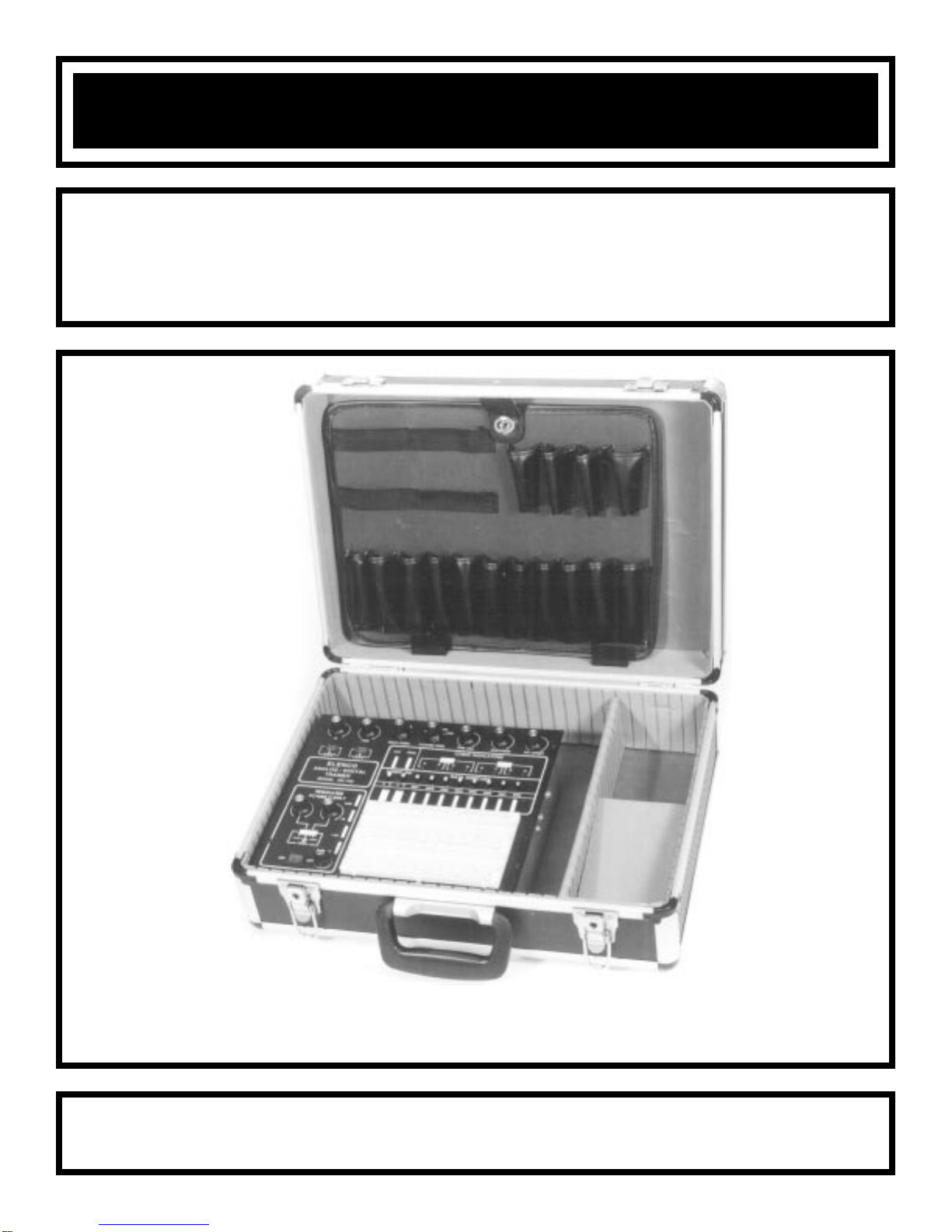
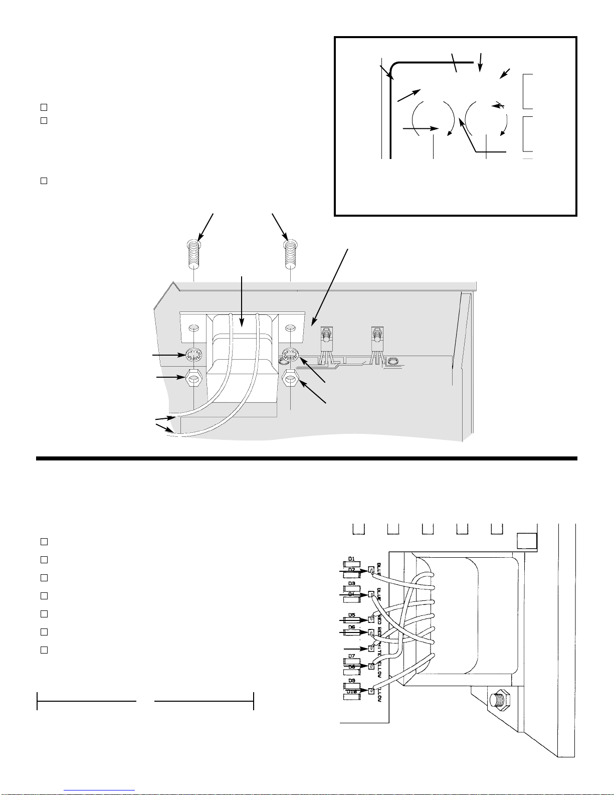
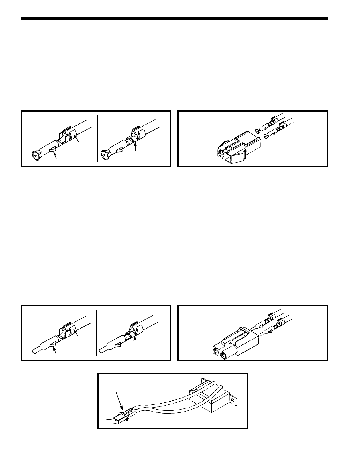
manuals.online logo
Brands
  1. Home
  2. •
  3. Brands
  4. •
  5. Elenco Electronics
  6. •
  7. Measuring Instrument
  8. •
  9. Elenco Electronics XK-700-SEMI User guide

Elenco Electronics XK-700-SEMI User guide

Other Elenco Electronics Measuring Instrument manuals

Elenco Electronics XK-700 User manual

Elenco Electronics

Elenco Electronics XK-700 User manual

Elenco Electronics XK-550 User manual

Elenco Electronics

Elenco Electronics XK-550 User manual

Elenco Electronics LP-525K User guide

Elenco Electronics

Elenco Electronics LP-525K User guide

Elenco Electronics TWT-1 User manual

Elenco Electronics

Elenco Electronics TWT-1 User manual

Elenco Electronics TT-400K User guide

Elenco Electronics

Elenco Electronics TT-400K User guide

Elenco Electronics K-38 User guide

Elenco Electronics

Elenco Electronics K-38 User guide

Elenco Electronics M-2666K User guide

Elenco Electronics

Elenco Electronics M-2666K User guide

Elenco Electronics CS-440 User guide

Elenco Electronics

Elenco Electronics CS-440 User guide

Elenco Electronics K-37 User guide

Elenco Electronics

Elenco Electronics K-37 User guide

Elenco Electronics TWT-1K User guide

Elenco Electronics

Elenco Electronics TWT-1K User guide

Elenco Electronics XK-550K User guide

Elenco Electronics

Elenco Electronics XK-550K User guide

Elenco Electronics XK-700 User manual

Elenco Electronics

Elenco Electronics XK-700 User manual

Elenco Electronics XK-700K User guide

Elenco Electronics

Elenco Electronics XK-700K User guide

Elenco Electronics DT-100K User guide

Elenco Electronics

Elenco Electronics DT-100K User guide

Elenco Electronics CS-600 User manual

Elenco Electronics

Elenco Electronics CS-600 User manual

Popular Measuring Instrument manuals by other brands

Powerfix Profi 278296 Operation and safety notes

Powerfix Profi

Powerfix Profi 278296 Operation and safety notes

Test Equipment Depot GVT-427B user manual

Test Equipment Depot

Test Equipment Depot GVT-427B user manual

Fieldpiece ACH Operator's manual

Fieldpiece

Fieldpiece ACH Operator's manual

FLYSURFER VIRON3 user manual

FLYSURFER

FLYSURFER VIRON3 user manual

GMW TG uni 1 operating manual

GMW

GMW TG uni 1 operating manual

Downeaster Wind & Weather Medallion Series instruction manual

Downeaster

Downeaster Wind & Weather Medallion Series instruction manual

Hanna Instruments HI96725C instruction manual

Hanna Instruments

Hanna Instruments HI96725C instruction manual

Nokeval KMR260 quick guide

Nokeval

Nokeval KMR260 quick guide

HOKUYO AUTOMATIC UBG-05LN instruction manual

HOKUYO AUTOMATIC

HOKUYO AUTOMATIC UBG-05LN instruction manual

Fluke 96000 Series Operator's manual

Fluke

Fluke 96000 Series Operator's manual

Test Products International SP565 user manual

Test Products International

Test Products International SP565 user manual

General Sleep Zmachine Insight+ DT-200 Service manual

General Sleep

General Sleep Zmachine Insight+ DT-200 Service manual

Sensa Core Lacto Spark user manual

Sensa Core

Sensa Core Lacto Spark user manual

VOLTCRAFT UTS-1980 operating instructions

VOLTCRAFT

VOLTCRAFT UTS-1980 operating instructions

EBCHQ 94915 Operation manual

EBCHQ

EBCHQ 94915 Operation manual

Balluff BIP LD2-T017-01-EP-S4 Series user guide

Balluff

Balluff BIP LD2-T017-01-EP-S4 Series user guide

Pulsar IMP Lite Series instruction manual

Pulsar

Pulsar IMP Lite Series instruction manual

ETCR 6800 user manual

ETCR

ETCR 6800 user manual

manuals.online logo
manuals.online logoBrands
  • About & Mission
  • Contact us
  • Privacy Policy
  • Terms and Conditions

Copyright 2025 Manuals.Online. All Rights Reserved.

DIGITAL / ANALOG TRAINER
MODEL XK-700-SEMI
A COMPLETE MINI-LAB FOR BUILDING,TESTING
AND PROTOTYPING ANALOG AND DIGITAL CIRCUITS
Elenco Electronics, Inc.
Copyright © 1997 Elenco Electronics, Inc. REV-C Revised 2001 753045
Assembly & Instruction Manual
INTRODUCTION
The XK-700-SEMI Digital/Analog Trainer is basically divided into four sections: Bredboard, Power Supply,
Analog and Digital. The bredboard was sent to you in an earlier kit.The PC board that contains the majority of
the circuits has come to you preassembled - HANDLE IT CAREFULLYas parts can be broken or moved and
could cause the circuit to malfunction. Follow the instructions carefully and perform all tests required. When
the assembly of the trainer has been completed, you will do a resistance and voltage analysis. If problems
occur, the troubleshooting chart at the end of each section will be helpful. After the Power Supply has been
established as functioning correctly, you will analyze the Analog Section even though it was preassembled. That
confirms that the circuit is functioning properly when it is powered up. The same procedure will be followed up
when checking the Digital Section.
POWER SUPPLY
The XK-700-SEMI has five built-in power supplies which will satisfy most design needs. This includes two
variable power supplies giving up to +20 volts and -20 volts at .5 amp. Below 15V, the current available is 1
amp. Three fixed power supplies give you +12VDC, -12VDC or +5VDC at 1 amp each. These fixed voltages
are the most commonly used voltages for design work. All supplies are regulated to within 150mV. This means
that you can increase the current draw from no load to .5 amp and the voltage will change less than 150mV. All
supplies are also short circuit protected by using integrated circuit regulator devices.
ANALOG TRAINER SECTION FUNCTION GENERATOR
The analog trainer contains a complete function generator capable of producing sine, square and triangle
waveforms. The frequency of the generator is continuously variable from one hertz to over 100,000 hertz in five
steps. A fine tuning control makes the selection of any frequency easy. The output voltage amplitude is variable
between 0 to 15Vpp. The output impedance is approximately 330 ohms.
DIGITAL TRAINER SECTION
The digital trainer has the necessary functions to do your digital experiments. They consist of a clock generator,
two no-bounce switches, eight LED indicator lamps and eight data switches.
POWER SUPPLY SPECIFICATIONS
Power Supplies:
• +1.25V to 20VDC @ .5 amp (1.25V to 15V @ 1 amp).
• -1.25 to -20VDC @ .5 amp (-1.25V to -15V @ 1 amp).
• +12V +5% @ 1 amp.
• -12V +5% @ 1 amp.
• +5V +5% @ 1 amp.
• 30VAC center tapped @ 1 amp.
• Load regulation - all DC supplies less than .2V no load to .5A.
• Line regulation - all DC supplies less than .2V 105 to 135V.
• Hum and ripple - all DC supplies less than .01V RMS.
• Short protection - all DC supplies-internal IC thermal cutoff.
• Fuse 1.25A 250V.
Variable Resistance (undedicated):
• 1kΩPotentiometer
• 100kΩPotentiometer
Bredboard - 2 bredboards containing 1,560 tie points.
USERS DESCRIPTION OF FRONT PANEL CONTROLS
1) On/Off Switch - Allows power to be applied to all outputs. Switch will
light when on.
2) Fuse Holder - Easy access for replacement of 1.25A fuse.
3) Power Output Terminals - This provides 30VAC center-tapped at
15 VAC; also provides output terminal for positive and negative
variable voltages.
4) Variable Positive Voltage Control - Varies positive voltage from 1.25
to 20V at indicated output connector pin.
5) Variable Negative Voltage Control - Varies negative voltage from
-1.25V to -20V at indicated output connector pin.
6) Output terminals for 1k and 100k undedicated potentiometers.
7) 1kΩundedicated potentiometer.
8) 100kΩundedicated potentiometer. -1-
1
2
3
4
5
6
7 8
-2-
XK-700-SEMI DIGITAL/ANALOG TRAINER PARTS LIST
QTY DESCRIPTION PART #
1 LM317 Integrated Circuit (U1) 330317
1 LM337 Integrated Circuit (U5) 330337
1 LM7805 Integrated Circuit (U3) 337805
1 LM7812 Integrated Circuit (U2) 337812
1 LM7912 Integrated Circuit (U4) 337912
1 Transformer 44K500
1 Fuse 1.25A 530125
1 Switch Illuminated 541204
4 Bracket L 4-40 tap 613008
1 Panel Top 614108
1 Panel Side Left 614506
1 Panel Side Right 614507
1 Panel Back 614508
4 Plastic Plug * 621050
9 Knob 622009
1 Case 623051
1 Strain Relief 624003
1 Spacer Nylon 7/16” 4-40 Tap 624013
1 Connector Receptacle 626020
1 Connector Plug 626021
9 Screw 4-40 x 1/4” Slotted Machine 641430
1
Screw 4-40 x 1/4” Phillips Flat Head
641431
6 Screw 6-32 x 5/16” Slotted Machine 641641
2 Screw 8-32 x 3/8” Phillips Machine 641840
4 Screw #4 x 1/4” Phillips AB 642430
4
Screw 4-40 x 1/4” Phillips Thrd Ct (23)
642432
4 Screw #6 x 1/2” Phillips AB 642662
4
Screw #6 x 3/8” Phillips Thread Cutting (25)
643652
* Used in Trainer Case Conversion Section on page 35.
QTY DESCRIPTION PART #
7 Nut 7mm 644101
2 Nut 9mm 644102
6 Nut 6-32 644601
2 Nut 8-32 644800
7 Washer 8mm x 14mm 645101
2 Washer 9mm x 15mm 645103
4 Washer #6 Black 645400
4 Washer Fiber 645404
2 Lockwasher #8 External 646828
1 Lug Solder #8 661002
1 Fuse Holder 663000
2 Terminal Male Crimp 666010
2 Terminal Female Crimp 666011
1 Manual 753045
5 Insulator Mica 780002
5 Insulator Washer 780101
1 Silicon Grease 790004
6” Wire #20 Red Stranded 813210
1 Line Cord 862105
2” Shrink Tubing 3/16” 890120
1” Shrink Tubing 1/4” 890701
2” Shrink Tubing 1/2” 891101
2” Shrink Tubing 3/4” 899110
1 PC Board Assembly 920550HK
1 9426 Bredboard 99426
1 9830 Bredboard 99830
1 Solder Tube 9ST4
Screw Identification
Phillips AB Screw 4-40 Thread Cutting Screw
#6 Thread Cutting Screw
Phillips
Slotted Machine
Screw
Flat Head Screw
Phillips
Phillips Machine Screw
-3-
PARTS VERIFICATION
Before beginning the assembly process, first familiarize yourself with the components and this instruction book.
Verify that all parts are present. This is done best by checking off each item in the parts list.
RESISTORS CAPACITORS
Trim Pot
Pot
Discap Mylar
Electrolytic (radial)
(Lytic) IC
SEMICONDUCTORS
INTEGRATED CIRCUIT
Diode
Transistor
IDENTIFYING CAPACITOR VALUES
Capacitors will be identified by their capacitance value in pF (picofarads), nF (nanofarads), or µF (microfarads).
Most capacitors will have their actual value printed on them. Some capacitors may have their value printed in
the following manner.
Second Digit
First Digit Multiplier
Tolerance
The above value is 10 x 1,000 = 10,000pF or .01µF
The letter K indicates a tolerance of +10%
The letter J indicates a tolerance of +5%
For the No. 01234589
Multiply By 1 10 100 1k 10k 100k .01 0.1
Multiplier
Note: The letter “R” may be used at times to
signify a decimal point; as in 3R3 = 3.3
IDENTIFYING RESISTOR VALUES
Use the following information as a guide in properly identifying the value of resistors.
BAND 1
1st Digit
Color Digit
Black 0
Brown 1
Red 2
Orange 3
Yellow 4
Green 5
Blue 6
Violet 7
Gray 8
White 9
BAND 2
2nd Digit
Color Digit
Black 0
Brown 1
Red 2
Orange 3
Yellow 4
Green 5
Blue 6
Violet 7
Gray 8
White 9
Multiplier
Color Multiplier
Black 1
Brown 10
Red 100
Orange 1,000
Yellow 10,000
Green 100,000
Blue 1,000,000
Silver 0.01
Gold 0.1
Resistance
Tolerance
Color Tolerance
Silver +10%
Gold +5%
Brown +1%
Red +2%
Orange +3%
Green +.5%
Blue +.25%
Violet +.1%
Bands
1 2 Multiplier
Tolerance
-4-
CONSTRUCTION
Introduction
Assembly of your XK-700-SEMI Digital/Analog Trainer Kit will prove to be an exciting project and give you much satisfaction and personal
achievement. If you have experience in soldering and wiring techniques, then you should have no problem with the assembly of this kit. Care
must be given to identifying the proper components and in good soldering habits. Above all, take your time and follow these easy step-by-
step instructions. Remember, “An ounce of prevention is worth a pound of cure”. Avoid making mistakes and no problems will occur.
CAUTION: WEAR SAFETY GLASSES WHEN ASSEMBLING THIS KIT.
Assemble Components
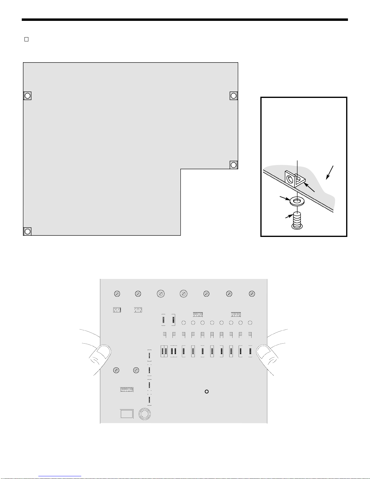
In all of the following assembly steps, the components must be installed on the top side of the PC board unless otherwise indicated. The
top legend shows where each component goes. The leads pass through the corresponding holes and the board is turned to solder the
component leads on the foil side. Solder immediately unless the pad is adjacent to another hole which will interfere with the placement
of the other component. Cut excessive leads with a diagonal cutter. Then, place a check mark in the box provided next to each step to
indicate that the step is completed. Be sure to save the extra leads for use as jumper wires if needed.
Soldering
The most important factor in assembling your XK-700-SEMI is good soldering techniques. Using the proper soldering iron is of prime
importance. A small pencil type soldering iron of 25 - 40 watts is recommended. The tip of the iron must be kept clean at all times
and well tinned. Many areas on the PC board are close together and care must be given not to form solder shorts. Size and care of
the tip will eliminate problems.
For a good soldering job, the areas being soldered must be heated sufficiently so that the solder flows freely. Apply the solder
simultaneously to the component lead and the component pad on the PC board so that good solder flow will occur. Be sure that the
lead extends through the solder smoothly indicating a good solder joint. Use only rosin core solder of 60/40 alloy.
DO NOT USE ACID CORE SOLDER! Do not blob the solder over the lead because this can result in a cold solder joint.
1. Solder all components from
the copper foil side only.
Push the soldering iron tip
against both the lead and the
circuit board foil.
Component Lead
Soldering Iron
Circuit Board
Foil
2. First apply a small amount of
solder to the iron tip. This
allows the heat to leave the
iron and onto the foil.
Immediately apply solder to
the opposite side of the
connection, away from the
iron. Allow the heated
component and the circuit
foil to melt the solder.
Solder
Soldering Iron
Foil
Example 1
Poor solder connections occur
when the lead is not heated
sufficiently. The solder will not
flow onto the lead as shown.To
correct. reheat the connection
and, if necessary, apply a small
amount of additional solder to
obtain a good connection.
Solder does not flow onto the
lead. A hard rosin bead
surrounds and insulates the
connection.
Poor solder
connection
Mount Part
Soldering iron
positioned incorrectly.
Example 2
A solder bridge occurs when
solder runs between circuit
paths and creates a short
circuit. This is usually caused
by using too much solder. To
correct this, simply drag your
soldering iron across the
solder bridge as shown.
4. Here is what a good solder
connection looks like. Cut
off excess leads.
3. Allow the solder to flow
around the connection.
Then, remove the solder and
the iron and let the
connection cool. The solder
should have flowed smoothly
and not lump around the wire
lead.
Solder Soldering Iron
Foil
Bend Leads to Hold Part Solder and Cut Off Leads
Foil Side
Rx - 100Ω5% 1/4W Resistor
(brown-black-brown-gold)
Note: One side of the bracket
is longer. Mount this side to
the PC board. Mount the
bracket to the top legend side
of the PC board with a 4-40 x
1/4” machine screw and a fiber
washer.
-5-
INSTALL COMPONENTS TO PC BOARD
Install the four L-brackets in the positions shown in Figure A. Mount them into position as shown in Figure B.
Figure A Figure B
Place the top panel onto the PC board and align the components with the holes in the top panel.
4-40 x 1/4”
Machine
Screw
Top Legend
Side of
PC Board
Fiber
Washer Longer Side
-6-
MOUNTING THE PC BOARD
Note: The holes in the two side panels have been punched differently. Be sure that you have the correct side
panel when mounting them to the PC board.
Mount the back panel using four 4-40 x 1/4” thread cutting screws (see Figure C).
Mount the PC board with four 4-40 x 1/4” machine screws (see Figure D). Do not tighten the screws.
4-40 x 1/4” Thread
Cutting Screws
4-40 x 1/4” Thread
Cutting Screws
Back Panel
Figure C
Right Side
Left Side
Figure D
4-40 x 1/4”
Machine Screws
4-40 x 1/4”
Machine Screws
Top Legend Side
of PC Board
Note: From the foil side of the PC board,
inspect the edges to be sure that there
are no component leads shorting against
the side panels.
Right Side
Left Side
-7-
MOUNT COMPONENTS TO THE SIDE PANELS
Mount U1, U3 and U5 to the left side panel as shown in Figure G.
Insert the pins of each IC into the holes of the PC board. Then,
with the hardware shown in Figure F, attach each IC to the side
panel. Solder the pins of the ICs to the PC board.
U3 - LM7805
U1 - LM317
U5 - LM337
Figure G
Mount the solder lug to the panel, as shown in Figure G, using a 6-32 x 5/16” screw and 6-32 nut.
Solder Lug
Mica
Side Panel
Insulator Washer
6-32 x 5/16”
Machine Screw
*Take a small amount of silicone grease from
the packet and apply it with a toothpick onto
the back of the ICs.
Figure F
6-23 Nut
* Silicone Grease
Mica
IC
IMPORTANT
Place the top panel on top of the unit. Push the PC board up until the
components come through the top panel and tighten the screws.
Adjust the PC
board height
with a 4-40 x
1/4” machine
screw.
Figure E
7805
LM317 LM337
Solder Lug U5
U1
U3 6-32 Nut
6-32 x 5/16”
Screw
Left Side
-8-
WIRE THE TRANSFORMER TO THE PC BOARD
Cut the blue, red, white and yellow wires on the transformer so they are 3” long and strip the insulation off of
the ends to expose 1/4” of bare wire. Solder the wires to the PC board starting with the top yellow wire as shown
in Figure I.
Yellow (F) wire to point F on the PC board
Blue (A) wire to point A on the PC board
Red (C) wire to point C on the PC board
White (E) wire to point E on the PC board
Red (D) wire to point D on the PC board
Blue (B) wire to point B on the PC board
Yellow (G) wire to point G on the PC board
Yellow (F)
Blue (A)
Red (C)
White (E)
Red (D)
Blue (B)
Yellow (G)
Figure I
3”
Mount U2 and U4 to the right side panel as shown in
Figure H. Insert the pins of each IC into the holes in the
PC board. Then, with the hardware shown in Figure FA,
attach each IC to the side panel. Solder the pins of the ICs
to the PC board.
U4 - LM7912
U2 - LM7812
Mount the transformer with the black wires as shown in
Figure H. Use the two 8-32 x 3/8” machine screws, #8
lockwashers, and 8-32 nuts.
Transformer mounted
#8-32 x 3/8” Machine Screws
6-23 Nut
IC
* Silicone Grease
Mica
Side Panel
Insulator Washer
6-32 x 5/16”
Machine Screw
* Take a small amount of silicone grease from the
packet and apply it with a toothpick onto the back of
the ICs. Figure FA
Mica
Yellow (G)
Blue (B)
Blue (A)
Red (D)
White (E)
Yellow (F)
Red (C)
Right Side
U4 U2
7812
7912
Figure H
Black Wires
8-32 Nut
#8 Lockwasher
#8 Lockwasher
8-32 Nut
Transformer
Note: Make sure that the transformer
does not touch U4.
-9-
HOW TO INSTALL CONNECTORS ONTO TRANSFORMER WIRES
A connector will be placed in the primary wires of the transformer. This will allow you to remove the top panel
from the trainer. Follow the procedures below.
1. Cut a six inch length off of each black primary wire.
2. Strip the insulation off of each end of the six inch wires to expose 1/4” of bare wire.
3. Place one wire onto the female pin and crimp the outer crimp tabs with pliers over the insulation as shown
in Figure 1A.
4. Crimp the inner tabs with pliers onto the bare wire as shown in Figure 1B and then solder the wire to the pin.
5. Connect the other female pin to the other wire using the same procedures above.
AB
Locking Tab
Female Pin Solder
Outer
Crimp Tab Inner
Crimp Tab
Female Housing
Figure 1 Figure 2
6. Insert the two pin/wire assemblies into the female housing as shown in Figure 2. Pull on the wire to check
that the pin is inserted all the way in. It should not pull out of the housing. The locking tabs should be bent
outward to hold the pin in the housing.
TRANSFORMER WIRES
1. Strip the insulation off of each of the black primary wires to expose 1/4” of bare wire.
2. Place the wire onto the male pin and crimp the outer crimp tabs with pliers over the insulation as shown in
Figure 3A.
3.
Crimp the inner tabs with pliers onto the bare wire and then solder the wire to the pin as shown in Figure 3B.
4. Connect the other male pin to the other primary wire using the same procedures above.
5. Insert the two pin/wire assemblies into the male housing as shown in Figure 4. Pull on the wire to check that
the pin is inserted all the way in. It should not pull out of the housing.
6.
Connect the male and female housing as shown in Figure 5. Note that the connector only fits together one way.
7. To detach the connector, push down on the end of the lock arm and pull the two apart.
Figure 3 Figure 4
AB
Locking Tab
Male Pin Solder
Outer
Crimp Tab Inner
Crimp Tab
Male Housing
Lock Arm
Figure 5