Elenco Electronics RCC-7K User guide

RADIO CONTROLLED CAR KIT
MODEL RCC-7K
Elenco Electronics, Inc.
Copyright © 2001 Elenco Electronics, Inc. 753288-G
Assembly and Instruction Manual

-1-
PARTS LIST
Contact Elenco Electronics if any parts are missing or damaged. DO NOTcontact your place of purchase
as they will not be able to help you.
CARD 1 - RESISTORS (in Bag 2)
QTY Symbol Value Marking Part #
1 R11 68W 5% 1/4W blue-gray-black-gold 126800
5 R12, R17, R18, R19, R20 100W 5% 1/4W brown-black-brown-gold 131000
1 R5 200W 5% 1/4W red-black-brown-gold 132000
2 R1, R21 560W 5% 1/4W green-blue-brown-gold 135600
2 R13, R14 1kW 5% 1/4W brown-black-red-gold 141000
2 R15, R16 1.5kW 5% 1/4W brown-green-red-gold 141500
1 R10 2.7kW 5% 1/4W red-violet-red-gold 142700
2 R4, R8 3.3kW 5% 1/4W orange-orange-red-gold 143300
2 R2, R3 22kW 5% 1/4W red-red-orange-gold 152200
1 R9 200kW 5% 1/4W red-black-yellow-gold 162000
2 R6, R7 3.9MW 5% 1/4W orange-white-green-gold 173900
CARD 2 - CAPACITORS (in Bag 2)
QTY Symbol Type Value Marking Part #
1 C1 Ceramic 10pF 10 211011
2 C2, C3 Ceramic 27pF 27 213010
1 C8 Ceramic 500pF 501 225080
1 C11 Ceramic or Mylar 2200pF 222 232217
1 C4 Ceramic or Mylar 3300pF 332 233310
2 C9, C10 Ceramic or Mylar 0.01mF 103 241031
1 C7 Ceramic or Mylar 0.1mF 104 251017
1 C5 Electrolytic 4.7mF 50V 4.7mF 264747
4 C6, C12, Electrolytic 220mF 10V 220mF 282244
C13, C14
CARD 2 - INDUCTORS & DIODES
QTY Symbol Type Value Part #
1 L2 Inductor 8.2mH (gray-red-gold-silver) 6RCC7K02E
1 D1 or D2 Zener Diode 3.0V (usually marked 3.0B2 or 3.6B1) 6RCC7K41
BAG 1 - PCB & SEMICONDUCTORS (6RCC7KB1E)
QTY Symbol Description Part #
1 IC1 IC GM2311A or AF2311 6RCC7K01E
1 IC1 IC socket, 16-pin 664016
1 T1 9 Turn inductor 6RCC7K03E
4 Q7, Q8, Q13, Q14 Transistor S8050, NPN 6RCC7K04
4 Q5, Q6, Q11, Q12 Transistor S8550, PNP 6RCC7K05
4 Q2, Q3, Q9, Q10 Transistor 9014, NPN 6RCC7K06E
1 Q1 Transistor C945, NPN 6RCC7K07E
1 - Printed Circuit Board 6RCC7K10E

BAG 3 - SCREWS (6RCC7KB3E)
QTY DESCRIPTION PART #
1 Screws 0.4” x 0.1” (10mm x 2.6mm) 640101
5 Screws 0.4” x 0.115” (10mm x 3.0mm) 640101E
6 Screws 0.3” x 0.1” (8mm x 2.6mm), 0.15” head 640102
BAG 4 - HARDWARE (6RCC7KB4E)
QTY DESCRIPTION PART #
2 Rear Springs 680023
1 Front Spring 680024
2 Shock Absorber Springs 680025
1 Rear Rod 0.8” x 0.075” 610808
(20mm x 2mm)
1 Steering Alignment Wire/Spring 6RCC7K11
2 Front Wheel Bars 6RCC7K12E
1 Battery Contact, + 6RCC7K13E
1 Battery Contact, - 6RCC7K14E
2 Battery Contact, + - 6RCC7K15E
1 Battery Contact, - + 6RCC7K16E
1 Switch, on/off 6RCC7K18E
1 Rear Axle 662019E1
1 Transmitter Antenna 484010E
BAG 5 - WIRES (6RCC7KB5E)
QTY DESCRIPTION PART #
1 Light Bulb, with wires attached 6RCC7K21
1 4” wire, red 6RCC7K22
1 4” wire, blue 6RCC7K23
1 4” wire, black 6RCC7K24
1 4” wire, green 6RCC7K25
1 4” wire, yellow 6RCC7K26
1 4” wire, orange 6RCC7K27
1 4” wire, white 6RCC7K29
1 Solder Roll 6RCC7K30
BAG 6 - COVERS (6RCC7KB6E)
QTY DESCRIPTION PART #
1 Front Section Cover 626018E1
1 Rear Section Cover 626019E
1 Steering Bar 626023E
1 Battery Cover 6RCC7K31E
2 Front Wheels 6RCC7K43E
2 Rear Wheels 626019E2
1 Top Light Bulb Cover 626022
BAG 7 - GEARS (6RCC7KB7E)
QTY DESCRIPTION PART #
2 Locators for Rear Wheels 626019E3
2 Turning Posts for Front Wheels 6RCC7K34E
1 Steering Alignment Post 6RCC7K36E
1 Gear, Rear Wheels Axle 626019E4
1 Steering Motor Bracket 626018E2
1 Gear, middle of rear section 610809
BAG 8 - MOTORS (6RCC7KB8E)
QTY DESCRIPTION PART #
1 Driving Motor (larger) 6RCC7K39
1 Steering Motor (smaller) 6RCC7K40E
1 0.01mF Disc Capacitors 241031
1 0.1mF Disc Capacitors 251017
1 Driving Motor Gear 6RCC7K37
1 Steering Motor Gear 626019E5
PACKAGED SEPARATELY
QTY DESCRIPTION PART #
1 Bottom Frame 6RCC7K42E
1 Top Frame 6AK870TFE
1 Car Antenna 484011E
1 Remote Control Transmitter, 6AK870TAE
Assembled Except for Antenna
1 Decorative Decals (1 Sheet) 720063E
-2-
You may have been given different screws from
those specified here (and usually some spares).
Contact Elenco if it is not clear which to use.

-3-
THEORY OF OPERATION
Remote Control Transmitter: (refer to the schematics and block diagram on p.31 as needed)
When the levers in the Remote Control Unit are pushed electrical contacts are made connecting the 9V battery
power to the transmitter and indicating which commands the user wants sent to the car. Forwards/Backwards
and Left/Right commands are controlled by different levers and use different sets of electrical contacts that are
used to encode a sequence of electrical pulses; the number of pulses depends on which command is being
sent. On some models Left/Right commands are only sent if Forwards/Backwards commands are also being
sent, since there is too much friction to turn the wheels unless the car is moving.
An electrical circuit that is tuned to a frequency of 27.9 MHz creates a signal that is sent to the antenna when
the pulses are active. The antenna converts this electrical energy into radio energy, creating a stream of radio
energy bursts, which travel through the air to be picked up by and understood by the radio receiver in the car.
The frequency of 27.9 MHz was selected for RCC-7K with the approval of the FCC (the US government) to
minimize radio interference between this product and all other electrical products.
Characteristics of Radio Reception:
Many factors affect the ability of the RCC-7K to receive commands from its Remote Control Transmitter. A weak
battery in the Transmitter will result in a weaker transmitted signal; if the battery is very weak then the Transmitter
may not function at all. The Transmitter’s ability to convert electrical energy to radio energy is best when its
antenna is fully extended and degrades as the antenna length is reduced; the same thing also applies to the car
antenna’s ability to convert the radio signal back into electrical energy for the receiver. The Transmitter’s
antenna transmits energy in all directions so as the range between it and the car is increased less energy is
received at the car. When operated with strong batteries and in an open area the range will be at least 40 ft.
Obstacles such as walls, furniture, and trees will degrade the radio signal’s ability to travel through air and
reduce operating range, but will never block it completely. In some cases more radio energy may travel from
the Transmitter to the car by going around obstacles than by going through them. In the car, weak batteries will
{
{
{
Pulse Sequence
27.9MHz Signal
Transmitted Signal
4 synchronization bursts each
~ 1.8ms long with ~ 600µs
spacing.
~~Burst sequence, each ~ 600µs long with
~ 600µs spacing.
10 bursts for forward; 34 bursts for forward-left;
28 bursts for forward-right; 40 bursts for backward;
46 bursts for backward-left; 52 bursts for backward-right.
Note: some models use different sequence lengths
~
~Sequence
Repeats
•
•••
•
•••
•
•••
Transmit Signals
INTRODUCTION
The RCC-7K is a radio-controlled car that you put together. It has 7 control functions: forward, forward-left,
forward-right, backward, backward-left, backward-right, and stop. The remote control operates at a frequency
of 27.9 MHz. It uses 4 AA batteries and one 9V battery (not included). It takes about 7 hours to build.
Assembly of the RCC-7K will prove to be an exciting project and give much satisfaction and personal
achievement. If you have experience in soldering and wiring technique, you should have no problems. For the
beginner, care must be taken in identifying the proper components and in good soldering habits. Above all, take
your time and follow the easy step-by-step instructions. Remember, “An ounce of prevention is worth a pound
of cure”.

reduce power to the Motor and degrade the receiver’s ability to filter, amplify, and decode commands from the
Transmitter.
Radio Receiver: (refer to the schematics and block diagram on p.31 as needed)
The car antenna collects radio energy and converts it back into electrical energy; the energy here will always
be much less than the energy originally applied to the transmitting antenna. If the car is turned on then the radio
receiver in the car is continuously monitoring the electrical energy from its antenna. The first stage of the
receiver is basically a filter which is tuned to amplify any energy around 27.9 MHz and block energy the antenna
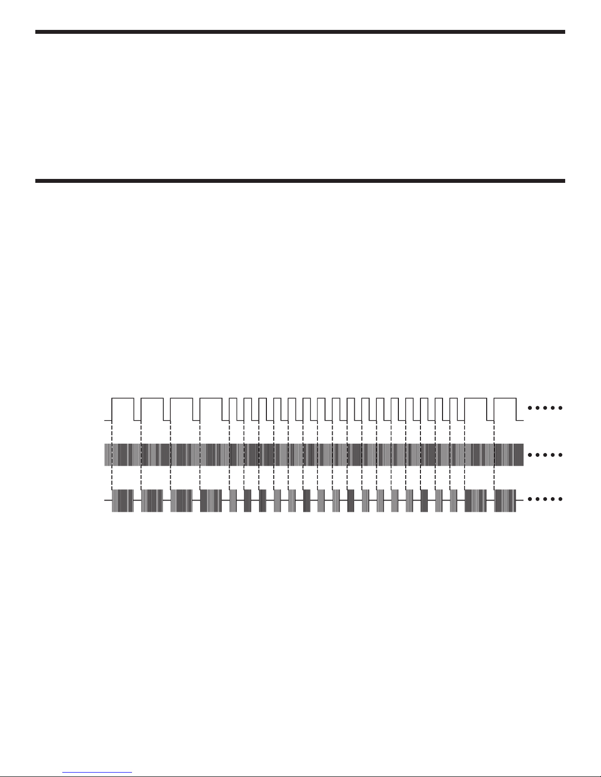
picks up outside this region. If the Remote Control Transmitter is sending commands then its radio signal will
be picked up by the receiver and converted back into the original pulse sequence. Decoding circuitry then
determines which commands were sent by measuring the number of received pulses in the sequence. Signals
are then sent to the motors to execute the commands.
Take a closer look at the receiver schematic. The sub-circuit centered around transistor Q1 filters the antenna
output, if an RCC-7K transmitter is operating nearby then the 27.9 MHz burst signal may be visible at its
collector. Inductor L1 is tuned so that the circuit amplifies around 27.9 MHz while rejecting all other frequencies.
But we really want the pulse sequence that is hidden in the 27.9 MHz signal, so then C10 is used to filter out
the 27.9 MHz from the burst signal we received. This result is applied to pin 14 of the AF2311 integrated circuit.
Inside AF2311 the signal is amplified and filtered in two stages between pins 14, 15, 16, 1, and 3. Pin 3 (DI) is
the output pulse sequence that was picked up by the receiver; this is used as the input to the decoder. The
AF2311 scans for the 4 long (synchronization) pulses and then counts the number of short pulses after them to
determine which command was sent by the transmitter. The gain of the AF2311 stages is high enough to
produce a pulse sequence at pin 3 even if no signal from a transmitter is present (it amplifies random noise),
but the resulting sequence will seldom be identified as one of the transmitter commands. Note from above that
there are 4 long pulses and 10 - 52 short pulses for each command, less pulses could have been used but then
the car is more likely to activate on random noise.
Pins 4 and 5 of AF2311 are a 100 kHz (±30%) oscillator that is used as a reference by the decoder.
Car Steering Mechanism: (refer to the schematics on p.31 as needed)
When a command is received to turn left, the AF2311 creates a voltage at pin 7 which turns on transistor Q9.
This then turns on Q11 and Q14 and current flows from the batteries through Q11, then through the steering
motor, and then through Q14 to ground. This current through the Motor creates a magnetic field. Inside the
motor is a small magnet which is connected to the gear you see on the outside of the motor. The magnetic field
turns the magnet in the motor, which turns the gear. The “teeth” on the gear grab the Steering Bar and pull it to
one side. Since the Front Wheels are connected to the Steering Bar, the car will turn.
To turn right, the AF2311 creates a voltage at pin 6 instead of pin 7. This turns on Q10, Q12, and Q13, and
current flows through the steering motor in the opposite direction. In turn this causes the steering gear, the
steering bar, and the car to turn in the opposite direction.
Car Drive Mechanism: (refer to the schematics as needed)
The Driving Mechanism works the same as the Steering Mechanism. When a command is received to go
forwards the AF2311 creates a voltage at pin 11 which turns on Q2. This then turns on Q5 and Q8 and current
flows from the batteries through Q5, then through the driving motor, and then through Q8 to ground. Similarly
to go backwards the voltage is created at pin 10, and Q3, Q6, and Q7 are turned on. The small gear on the
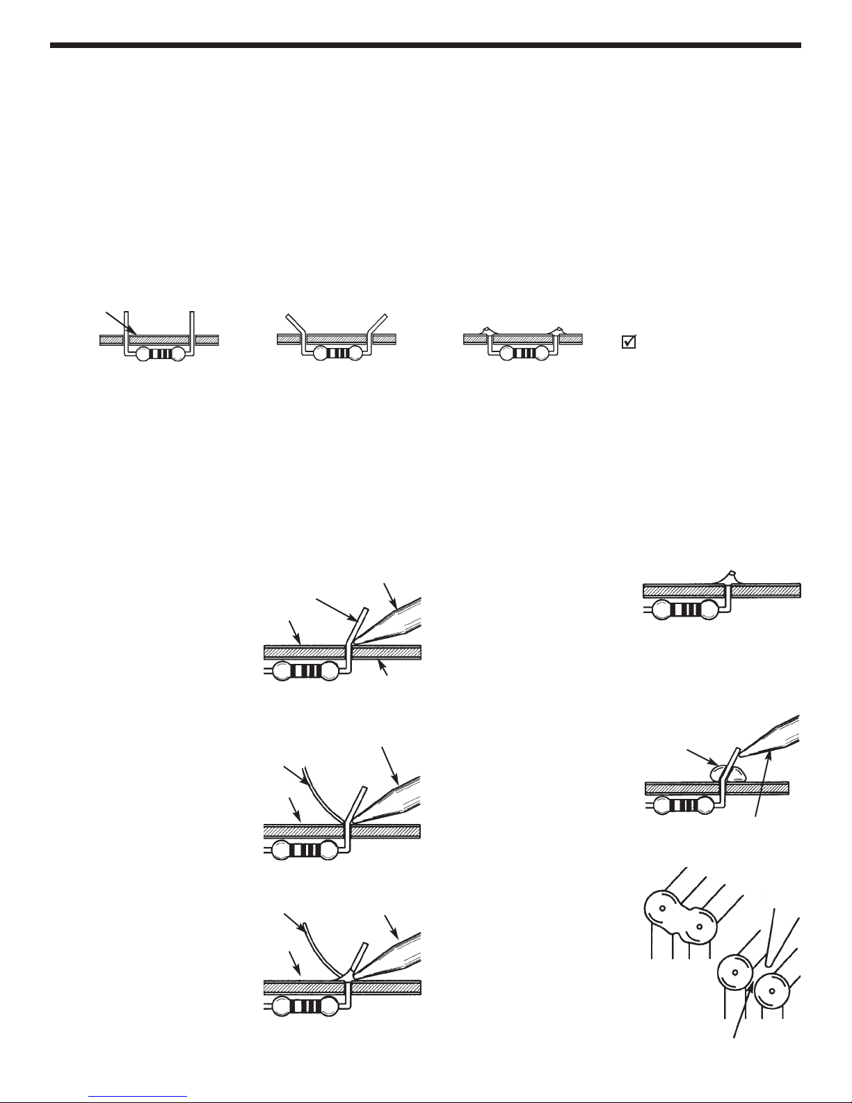
Motor drives the Middle Gear, which drives the gear on the rear wheels axle, making the wheels move. Note
that the gears on the Motor and the rear wheels axle rotate forward and the Middle Gear rotates backward to
drive the car forward, this is because interlocking gears spin in opposite directions. Also notice that between
the Motor gear and the Middle Gear and again between the Middle Gear and the Rear Wheels axle gear, the
number of “teeth” is increased by 4:1 and 5:1 respectively, for 20:1 overall. The Motor must rotate 20 times to
rotate the rear wheels once. The reason for this is that if the Motor were to drive the wheels directly then the
RCC-7K would be very hard to control.
-4-

-5-
CONSTRUCTION
Introduction
Assembly of your RCC-7K R/C Car Kit will prove to be an exciting project and give you much satisfaction and personal achievement. If
you have experience in soldering and wiring techniques, then you should have no problem with the assembly of this kit. Care must be
given to identifying the proper components and in good soldering habits. Above all, take your time and follow these easy step-by-step
instructions. Remember, “An ounce of prevention is worth a pound of cure”. Avoid making mistakes and no problems will occur.
CAUTION: WEAR SAFETY GLASSES WHEN ASSEMBLING THIS KIT.
Assemble Components
In all of the following assembly steps, the components must be installed on the top side of the PC board unless otherwise indicated. The
top legend shows where each component goes. The leads pass through the corresponding holes and the board is turned to solder the
component leads on the foil side. Solder immediately unless the pad is adjacent to another hole which will interfere with the placement
of the other component. Cut excessive leads with a diagonal cutter. Then, place a check mark in the box provided next to each step to
indicate that the step is completed. Be sure to save the extra leads for use as jumper wires if needed.
Soldering
The most important factor in assembling your R/C Car is good soldering techniques. Using the proper soldering iron is of prime
importance. A small pencil type soldering iron of 25 - 40 watts is recommended. The tip of the iron must be kept clean at all times
and well tinned. Many areas on the PC board are close together and care must be given not to form solder shorts. Size and care of
the tip will eliminate problems.
For a good soldering job, the areas being soldered must be heated sufficiently so that the solder flows freely. Apply the solder
simultaneously to the component lead and the component pad on the PC board so that good solder flow will occur. Be sure that the
lead extends through the solder smoothly indicating a good solder joint. Use only rosin core solder of 60/40 alloy.
DO NOT USE ACID CORE SOLDER! Do not blob the solder over the lead because this can result in a cold solder joint.
1. Solder all components from
the copper foil side only.
Push the soldering iron tip
against both the lead and the
circuit board foil.
Component Lead
Soldering Iron
Circuit Board
Foil
2. First apply a small amount of
solder to the iron tip. This
allows the heat to leave the
iron and onto the foil.
Immediately apply solder to
the opposite side of the
connection, away from the
iron. Allow the heated
component and the circuit
foil to melt the solder.
Solder
Soldering Iron
Foil
Example 1
Poor solder connections occur
when the lead is not heated
sufficiently. The solder will not
flow onto the lead as shown. To
correct. reheat the connection
and, if necessary, apply a small
amount of additional solder to
obtain a good connection.
Solder does not flow onto the
lead. A hard rosin bead
surrounds and insulates the
connection.
Poor solder
connection
Mount Part
Soldering iron
positioned incorrectly.
Example 2
A solder bridge occurs when
solder runs between circuit
paths and creates a short
circuit. This is usually caused
by using too much solder. To
correct this, simply drag your
soldering iron across the
solder bridge as shown.
4. Here is what a good solder
connection looks like. Cut
off excess leads.
3. Allow the solder to flow
around the connection.
Then, remove the solder and
the iron and let the
connection cool. The solder
should have flowed smoothly
and not lump around the wire
lead.
Solder Soldering Iron
Foil
Bend Leads to Hold Part Solder and Cut Off Leads
Foil Side
Rx - 100W5% 1/4W Resistor
(brown-black-brown-gold)

PART IDENTIFICATION CARDS
To help identify the resistors and diodes used in the construction of your car we have
mounted the resistors, capacitors, diodes, and an inductor onto cards. The card will
help you find the parts quickly. THE PARTS WILL NOT NECESSARILY BE LISTED IN
THE ORDER SHOWN IN THE PARTS LIST SECTION OR IN THE ASSEMBLY
PROCEDURE.
When you are ready to assemble the car kit, follow the procedure shown. For an
example refer to page 16. The first resistor called for is R13, 1kWresistor (brown-
black-red-gold). Locate it on the card ( ), verify that it is the correct value. Some
resistors may be mounted backwards on the card so you must be certain that you are
reading the resistors correctly. When the correct value has been established, only
then will you mount it into its correct position on the PC board.
IDENTIFYING CAPACITOR VALUES
Capacitors will be identified by their capacitance value in pF (picofarads) or mF (microfarads). Most capacitors
will have their actual value printed on them. Some capacitors may have their value printed in the following
manner.
Second Digit
First Digit
Multiplier
Tolerance
The above value is 10 x 1,000 = 10,000pF or .01mF
The letter K indicates a tolerance of +10%
The letter J indicates a tolerance of +5%
Note: The letter “R” may be used at times to
signify a decimal point; as in 3R3 = 3.3
IDENTIFYING RESISTOR VALUES
Use the following information as a guide in properly identifying the value of resistors.
BAND 1
1st Digit
Color Digit
Black 0
Brown 1
Red 2
Orange 3
Yellow 4
Green 5
Blue 6
Violet 7
Gray 8
White 9
BAND 2
2nd Digit
Color Digit
Black 0
Brown 1
Red 2
Orange 3
Yellow 4
Green 5
Blue 6
Violet 7
Gray 8
White 9
Multiplier
Color Multiplier
Black 1
Brown 10
Red 100
Orange 1,000
Yellow 10,000
Green 100,000
Blue 1,000,000
Silver 0.01
Gold 0.1
Resistance
Tolerance
Color Tolerance
Silver +10%
Gold +5%
Brown +1%
Red +2%
Orange +3%
Green +.5%
Blue +.25%
Violet +.1%
FortheNo.01234589
Multiply By 1 10 100 1k 10k 100k .01 0.1
Multiplier
12Multiplier
Tolerance
-6-

ASSEMBLY INSTRUCTIONS
Inspection of Parts: Take a look at each of the parts bags and compare to the Parts List (on pages 1 &
2). Be sure that nothing was damaged during shipment and handling. Contact Elenco Electronics if you
have any problems (phone number is on the back of this manual).
-7-
Remote Control Transmitter
Transmitter Antenna
9V Battery Slot
(Alkaline recommended) Note: Screw in tight.
1
2
Battery Contact,
Battery Contacts
+ ,
Battery Contact, +
Battery Contact, +
Battery Cover
Back of
Bottom Frame
NOTE: Slide
the contacts into
the slots and then
fold back the tabs on
the top side to hold
in place.
Switch Placement
Insert the switch onto the posts. Then,
secure by melting the plastic posts with
a soldering iron.
Switch
Posts
Snap In Tab
Red Wire Black Wire
White Wire

-8-
3
Bottom Frame
Driving Motor Interior Tab
Side
Tab
Interior Tab:
Bend Tab 90O,
but don’t short
to motor shell.
Driving Motor
Gear
Quick Test: Connect a
1.5V battery across the
motor wires with your
hands. The motor should
spin.
Side Tab:
bend tab back
180Oand solder
to motor shell
0.1mF Capacitor
(marked 104):
Solder leads to motor
tabs, one lead is also
soldered to motor
shell.
You cannot get good connections
soldering to the motor shell unless
you first file or scrape away a
small area of the outer coating.
Green Wire
Yellow Wire
Driving Motor
(the larger motor; Yellow
wire goes to tab next to
Åmarking in plastic)
Å
Å
NOTE: If you
have a problem
putting the gear on
the shaft of the motor,
then gently tap the
gear on with a hard
object.

-9-
Locators
Rear Axle:
the “grip” near the
middle should be
toward the left
Locator Slots
NOTE: The
next 3 steps will be
much easier if you
elevate the car about
1” using a small
object.
4
Gear for rear axle:
slide on until it is
firmly in the
“grips” on the axle
Rear Wheels

-10-
Quick Test: All 3 gears
should be lined up and
turning one of them by hand
should also turn the others.
NOTE: Put some
Vaseline or grease into
the slots for the rod and
some on the teeth of all the
gears (motor gear, middle
gear, and the rear axle
gear). This will make the
car go faster.
Gear, Middle of rear section
Rear Rod
5
Check the alignment of the
gears. The middle gear
must not be able to slide
out of alignment with the
other gears. Adjust the
positions of the gears on
the motor and rear axle if
necessary.

-11-
Screw Used
(shown actual size)
0.4” x 0.115”
X2
0.4” x 0.115” Screws
Rear Section
Cover
NOTE: Make
sure that the wires
from the ON/OFF switch
and the motor run out of
the rear section cover
through the slots (as
shown) without being
damaged.
6
Quick Test: Lift the wheels off the ground so they
may spin freely. Connect a 1.5V battery across the
motor wires with your hands, (+) terminal to green
wire. The wheels should spin forward slowly but
smoothly. Reverse the wires to the battery and the
wheels should spin backwards.
Note: Try to also press down on the forward part of
the rear cover while doing this, since the forward
screws for it have not been installed yet.

-12-
Steering Bar
Between the Wires
Wires
7
Hammer the
bars into the
wheels, but leave a
small space so that
the turning posts
may spin freely.
Front
Wheels
Front
Wheel
Bars
Turning Posts for
front wheels
Steering
Alignment
Adjustment
(triangular piece will
lean against this)
post is towards
front of car
Spring for Steering
Centering
Bend wires to fit around post.
They must NOT be tight (or the
steering won’t work), stretch
the wire with your fingers to
loosen it if necessary.
Note direction
of post.
After inserting wire on it,
melt the top of this post
with a soldering iron to
keep the spring in place.
front
of car

-13-
Steering Motor
Gear
Right Front Wheel
Left Front Wheel
NOTE: If you
have a problem
putting the gear on
the shaft of the motor,
then gently tap the
gear on with a hard
object.
8
NOTE: The
next 3 steps will be
much easier if you
elevate the car about
1” using a small
object.
NOTE: The gear
should lay on the
teeth of the steering
bar. Add some
Vaseline or grease to
the teeth.
Quick Test: Turning one
wheel by hand should also
turn the other wheel and
move the gear along the
steering bar.
Quick Test: Connect a 1.5V
battery across the motor wires
with your hands - the motor
should spin. Reverse the wires to
the battery and the motor should
spin in the opposite direction.
Side Tab:
bend tab back
180Oand solder
to motor shell
0.01mF Capacitor
(marked 103):
Solder leads to motor tabs, one lead is
also soldered to motor shell.
You cannot get good
connections soldering to
the motor shell unless
you first file or scrape
away a small area of the
outer coating.
Orange Wire
Blue Wire
Steering Motor
(the smaller motor; Blue
wire goes to tab next to
Åmarking in plastic)
Å
Å
Screw Used
(shown actual size)
0.3” x 0.1”
X2 0.3” x 0.1” Screws

-14-
Front Wheel Shock Absorbers
Front Spring
Post
9

-15-
Screw Used
(shown actual size)
0.3” x 0.1”
X2
0.3” x 0.1” Screws
Front Wheels Section Cover
10
Quick Test: Install 4 fresh AA alkaline batteries in
the battery cage, observing their polarity while
doing so. Lift the front wheels off the ground so they
may spin freely. Touch the steering motor wires to
the left-front and left-rear battery contacts with your
hands. The front wheels should turn to one side (as
the steering motor gear moves along the steering
bar). Reverse the wires to the batteries and the
wheels should turn in the opposite direction.

-16-
11
Figure B
Lay resistor flat against the
PC board.
ASSEMBLE THE FOLLOWING COMPONENTS TO THE PC BOARD
Review the soldering and parts identification instructions on p.5 at this time. In all of the following steps the
components must be installed on the top legend side of the PC board. The board is turned over to
solder the component leads.
Figure D
Align the notch on the socket (if any) with
the notch marked on the PC board. Solder
the socket to the PC board. Insert the IC
into the socket with the notch as shown.
The marking on the board is
wrong for this part. Mount using
the 2 right holes, with the band
pointing towards the center hole.
This is shown here.
Figure C
Band
Notch
Figure A
this hole is not used
L1 - 9 Turn Inductor (this part
has been pre-tuned, you do not
need to adjust it).
(see Figure A)
R13 - 1kW5% 1/4W Res.
(brown-black-red-gold)
(see Figure B)
R14 - 1kW5% 1/4W Res.
(brown-black-red-gold)
(see Figure B)
D2 - 3V Zener Diode
(see Figure C)
Note: “D1” (as marked on the
PC board) is not used. Place
the diode you were given (which
may be marked on your parts
card as D1) here.
IC1 - 16-pin IC Socket
IC1 - AF2311 Integrated
Circuit (see Figure D)

(see Figure E)
R11 - 68W5% 1/4W Res.
(blue-gray-black-gold)
R18 - 100W5% 1/4W Res.
R17 - 100W5% 1/4W Res.
R12 - 100W5% 1/4W Res.
(brown-black-brown-gold)
R15 - 1.5kW5% 1/4W Res.
(brown-green-red-gold
R19 - 100W5% 1/4W Res.
R20 - 100W5% 1/4W Res.
(brown-black-brown-gold)
R16 - 1.5kW5% 1/4W Res.
(brown-green-red-gold)
R9 - 200kW5% 1/4W Res.
(red-black-yellow-gold)
R8 - 3.3kW5% 1/4W Res.
(orange-orange-red-gold)
(see Figure E)
R21 - 560W5% 1/4W Res.
(green-blue-brown-gold)
R10 - 2.7kW5% 1/4W Res.
(red-violet-red-gold)
R4 - 3.3kW5% 1/4W Res.
(orange-orange-red-gold)
R3 - 22kW5% 1/4W Res.
R2 - 22kW5% 1/4W Res.
(red-red-orange-gold)
R1 - 560W5% 1/4W Res.
(green-blue-brown-gold)
R5 - 200W5% 1/4W Res.
(red-black-brown-gold)
R6 - 3.9MW5% 1/4W Res.
R7 - 3.9MW5% 1/4W Res.
(orange-white-green-gold)
-17-
Figure E
Stand resistor on end as shown with the
body inside the white circle (if a white
circle is present).
White
Circle
12
R3

(see Figure G)
C6 - 220mF Lytic Capacitor
C12 - 220mF Lytic Capacitor
C13 - 220mF Lytic Capacitor
C5 - 4.7mF Lytic Capacitor
C14 - 220mF Lytic Capacitor
(see Figure F)
C1 - 10pF (10) Capacitor
C10 - 0.01mF (103) Capacitor
C2 - 27pF (27) Capacitor
C3 - 27pF (27) Capacitor
C7 - 0.1mF (104) Capacitor
C8 - 500pF (501) Capacitor
C4 - 3,300pF (332) Capacitor
C9 - 0.01mF (103) Capacitor
C11 - 2,200pF (222) Capacitor
-18-
Figure G
Mount the
electrolytic
capacitor as
shown, noting the
polarity as
shown.
13
L2 - 8.2mH 10% Inductor
(gray-red-gold-silver)
Stand inductor on end as shown.
Figure F
Mount the ceramic or mylar
capacitor as shown below.

(see Figure H)
Q5 - S8550 Transistor
Q6 - S8550 Transistor
Q8 - S8050 Transistor
Q2 - 9014 Transistor
Q3 - 9014 Transistor
Q7 - S8050 Transistor
Q14 - S8050 Transistor
Q12 - S8550 Transistor
Q9 - 9014 Transistor
Q10 - 9014 Transistor
Q13 - S8050 Transistor
Q11 - S8550 Transistor
Q1 - C945 Transistor
-19-
Inspection:
Double check that you have installed all of your parts in
the proper places. Be sure they are not touching each
other and creating short circuits. Inspect all solder
connections and make sure none of them are weak. Use
a magnifying glass if you have one. Check all solder
connections for short circuits. Be thorough as it is much
easier to find and correct problems now rather than later.
Figure H
Mount the transistor with
the flat side in the same
direction marked on the
PC board.
1/8”
14
Other manuals for RCC-7K
1
Table of contents
Other Elenco Electronics Motorized Toy Car manuals