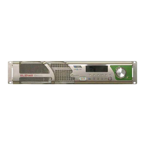
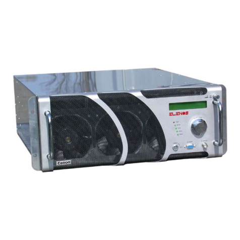
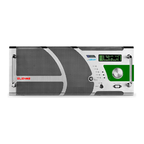
Elenos ETG 2000.20 User manual

Rev. 02− 16/12/2019
Cod. MAN1046UUK
USER MANUAL
ETG 2000.20
ETG 1000.10
ETG 500.5
ETG 150
ETG 20
FM SOLID STATE TRANSMITTER WITH AUDIO CHANGEOVER OPTION

Operative Office: via G. Amendola 9,
44028 Poggio Renatico (Fe) ITALY
C.C.I.A.A. 101 216, C.Fisc. e P.IVA IT00415540384
We kindly remind you to register your product onhttp://www.elenos.com/product−
registration/
For further information and help please contact the Customer Service:
Elenos
Ph : +39 0532 829965
Fax : +39 0532 829177
Internet web site : www.elenos.com
Elenos USA
2561 NW 74th Ave, Unit A−16, 33122 Miami (Florida), Ph +1 855−305−3058
We kindly recommend you to fill in the RMA module (ITA http://www.elenos.com/it/
elenos−rma/o ENG http://www.elenos.com/elenos−rma/) and to report the apparatus
serial number (available on identification label).
All copyrights are reserved, you may not reproduce any part of this manual, in any form, without
the express written permission of Elenos S.r.l.
UNI EN ISO 9001:2008 certified company
Certificate No.102222A
Elenos s.r.l. declares that the equipment in this documentation complies with
1999/05/CE Directive.
For details see “CE Conformity” Section.

Revision history
Revision
no. Date(dd/mm/yy) Description
00 01/12/2017 First release
01 26/06/2018 Updated para 6 “Datasheet”
16/12/2019 Updated model range
02

Index
Index
4
1 Informative letter 7................................................
1.1 Personnel in charge 8......................................
1.2 Warranty 8................................................
1.3 Exclusion 9................................................
1.4 Exemption from liability 9....................................
2 Safety 11.........................................................
2.1 Safety precautions 13.......................................
2.2 First aid 15................................................
2.2.1 Treatment of electrical burns 15..............................
2.2.1.1 Extensive burns and skin cuts 15.....................
2.2.1.2 Less severe burns (1st and 2nd degree) 15............
2.2.2 Treatment of electric shocks 15..............................
2.2.2.1 If the victim is unresponsive 15.......................
2.2.2.2 If the victim is responsive 16.........................
2.3 Workplace characteristics 16................................
2.3.1 Room characteristics 16.....................................
2.3.2 Electrical system features 16................................
2.4 Exposure evaluation 18.....................................
2.4.1 Calculation in the free space 18..............................
2.4.1.1 Electric field values (V/m) as a function of power (W) and
distance. 20........................................
3 CE conformity 21.................................................
3.1 CE conformity 23...........................................
3.2 Labels 26.................................................
3.2.1 Identification label 26.......................................
3.2.2 Assistance label 26.........................................
3.2.3 Warranty label 26..........................................
3.2.4 Serial number label 26......................................
4 Product description 27............................................
4.1 Controls and connections overview 29........................
4.2 Contnectors pin assignment 30..............................
4.2.1 EIA485 − Telemetry − Ethernet − Interlock 30..................
4.2.2 TC/TS − Profiles 30.........................................
4.2.3 Stereo L/R − AES/EBU 31...................................
4.2.4 Aux1 − Aux2 − MPX − MPX Monitor 31........................
4.2.5 RF Monitor 31.............................................
4.2.6 Line Input − Grounding 31...................................
4.3 Safeness algorithms 32.....................................
4.3.1 Software’s protections 32....................................
4.3.1.1 IPF (Intelligent Proportional Foldback) 32..............
4.3.1.2 IPC (Intelligent Power Control) 32.....................

Index
Index
5
4.3.1.3 Safety Management (“Lifextender”)R32................
5 Block diagrams 35.................................................
5.1 Block diagram 37............................................
5.1.1 ETG 2000.20 37............................................
5.1.2 ETG 1500.15 / ETG 1000.10 38...............................
5.1.3 ETG 700.7 / ETG 500.5 / ETG 300.3 / ETG 150 39..............
5.1.3 ETG 20 39............ ....................................
6 User instructions 41................................................
6.1 User interface 43............................................
6.1.1 Menu tree 44...............................................
6.1.2 TX Control Panel (Main Window) 45...........................
6.1.3 System Menu !System Config (1 of 2 and 2 of 2) 46............
6.1.4 System Menu !Communication Port Set / System Info 47.......
6.1.5 System Menu !System Time / Clock Pwr Target 1 of 2 48.......
6.1.6 System Menu !Clock Pwr Target 2 of 2 / Telemetry Config 49....
6.1.7 Inputs Menu !Base Band Levels / Change Over Inputs 50......
6.1.8 Inputs Menu !Input Sensitivity Settings 51....................
6.1.9 RF & PWR Menu !View TX Parameters (1 of 2 and 2 of 2) 52...
6.1.10 Password Menu !Password / Password Setting 53........
6.1.11 Password Menu !Password Recovery 54................
6.1.12 Alarm Menu !Alarm List / Event History 55...............
6.1.13 Alarm Menu !User Alarm Data / User Alarms Timers 56...
6.1.14 Alarm Menu !Audio Trim and Alarms 57.................
6.1.15 Diagnostic Menu !UART 0 Info / UART 1 Info 58..........
6.1.16 Diagnostic Menu !UART 2 Info 59......................
6.2 Alarms/Warnings/Status list 61................................
6.3 External connectable devices 65..............................
6.3.1 Connecting to a LAN/PC 65..................................
6.3.2 Connecting to a Change Over/Audio Matrix 66..................
7 Datasheet 67......................................................
7.1 Datasheet 68...............................................
8.1.1 Individual models specific parameters 70...............
7.2 ETG models layouts 71......................................
7.2.1 ETG 2000.20 71............................................
7.2.2 ETG 1500.15 72............................................
ETG 1000.10 72
............................................
7.2.3 ETG 700.7 / ETG 300.3 / ETG 500.5 / ETG 150 73..............
7.2.4 ETG 20 74.................................................
8 Maintenance 75....................................................
8.1 Maintenance 76.............................................
8.1.1 Periodic checks and replacements 76..........................

Index
6

Dear Customer,
Thank you for choosing an Elenos product.
ELENOS s.r.l. produces solid state VHF/FM sound broadcasting transmitters
ranging from minimum power of 10W to maximum power of 30kW, exchange
units, remote control units, etc.
The equipment has been produced to ensure constant performance over time
as long as periodical controls and essential maintenance works are carried out
as required.
However, before attempting any kind of operation an accurate reading of this
manual and of all relevant documentation attached is recommended to the user.
ELENOS s.r.l. Management
Informative letter
Informative letter 7
WARNING
This device can only be used by holders of
all the authorizathion provided by the com-
petent Authorities of the specific country.
Elenos s.r.l.
1 Informative letter
1 Informative letter 7...............................................
1.1 Personnel in charge 8.....................................
1.2 Warranty 8...............................................
1.3 Exclusion 9...............................................
1.4 Exemption from liability 9...................................

Informative letter
8
1.1 Personnel in charge
This manual has to be intended as an integral part constituting the equipment, and
must be readily at hand to all the personnel responsible for its installation, use
and maintenance.
The installation, use and maintenance of the device concerned in this case
must be permitted exclusively to properly trained and qualified personnel,
who must have received the appropriate training on the use of the equipment and
who are aware of every possible risk occurring when operating with devices connec-
ted to dangerous voltage electrical networks, operating with high internal voltages
and generating high radiofrequency output power.
This manual does not claim to be a comprehensive collection of safety standards
required for the use of the equipment.
However, the user and the maintenance technician are required to know the
content of these manual and of all its connected attachments.
This equipment must be used only by holders of governmental licenses and/or
ministerial authorizations only.
1.2 Warranty
The products sold to the Customer by Elenos Srl are covered by a 24−month warranty
starting from the FOB date of shipment from Elenos Srl site; this warranty is granted
both to the Customer and to any other possible subsequent purchaser of the product
and covers any kind of fault caused by defective components of the product itself, as
long as it is maintained in an excellent controlled condition. It is essential to the effecti-
ve coverage of the warranty issued by Elenos Srl the registration of the product by
the Customer through the web site www.elenos.com/product−registration/.
In case the Customer detects a failure under warranty, he must give immediate written
notice to Elenos Srl and send the product at his own expense to the Elenos Srl hea-
dquarter or to the nearest qualified Elenos Srl centre; in case of shipment to its hea-
dquarter, the latter agrees to replace within the next 45 days for free the defective
component; in case of shipment to a qualified service Elenos Srl, the latter shall
refund the cost of the intervention on the faulty component on the basis of a fixes and
agreed tariff in advance between the customer and Elenos Srl. If the product purcha-
sed by the customer forms part of the so−called products “Reduced mobility” (weight
higher than Kg. 50 (110lb), the maintenance or replacement of the defective compo-
nent will be in the place where the equipment is located and will be done by the techni-
cians of the closer technical center qualified by Elenos Srl. All this after the evaluation
by a technician designated from Elenos on the presence of a case of exclusion from
the guarantee.
For details, please consult the Terms and Conditions documents.

Informative letter 9
1.3 Exclusion
The customer expressly accepts the exclusion from the terms of Elenos Srl warranty’s
coverage all damages caused by electrical discharges (lighting) and incorrect power sup-
ply voltages, as well as by the Customer’s negligence, carelessness or unskillfulness, or
by unauthorized staff maintenance operations or by replacements of original parts of the
equipment with new systems or spare parts not directly supplied by Elenos Srl or by its aut-
horized distributors, or by a use of the product other than those intended for the same pro-
duct, or from any action or fact attributed to third parties who have access to the product
for the same Customer’s approval or even without the Customer being aware thereof after
that the latter has received the delivery of the products.
The warranty expressly excludes coverage for damages caused by fires, floods, or other
natural disasters, wars, revolts, as well as in all cases the equipment becomes the mate
rial object of a crime.
The warranty is also expressly excluding coverage for damages occurred after the delivery
of the equipment by Elenos Srl to the carrier, being the Customer responsible for any risk
related to the transport, since its time−frames, costs and methods are chosen and covered
by the same Customer.
1.4 Exemption from liability
The customer is responsible for installation, maintenance and control products, as well as
verification that the climatic and environmental conditions, in which the products are pla-
ced, are suitable for their use and do not affect the operation. All in observance of Elenos
Srl’s manual attached to the product purchased, that must be the reference for the custo-
mer to require validly and effectively the replacement or repair under warranty. Conversely,
if the customer fails to observe the precepts contained in the instruction manual, as well
as the minimum care required to the normal user of such equipment, the guarantee granted
by Elenos Srl will not operate and the customer himself will totally assume the risk of any
damages occurred to the products.
Elenos Srl reserves the right to make possible changes to parts, details and accessories
that may be considered opportune to be done for the improvement of the equipment, or
to meet the needs connected to constructive and commercial requirements, in any
moment, without prior notice of it and without committing to upgrade immediately this
manual.
For details, please consult the Terms and Conditions documents.

Informative letter
10

Informative letter
Safety 11
2 Safety
2 Safety 11.......................................................
2.1 Safety precautions 13.....................................
2.2 First aid 15..............................................
2.2.1 Treatment of electrical burns 15............................
2.2.1.1 Extensive burns and skin cuts 15...................
2.2.1.2 Less severe burns (1st and 2nd degree) 15..........
2.2.2 Treatment of electric shocks 15............................
2.2.2.1 If the victim is unresponsive 15.....................
2.2.2.2 If the victim is responsive 16.......................
2.3 Workplace characteristics 16..............................
2.3.1 Room characteristics 16...................................
2.3.2 Electrical system features 16..............................
2.4 Exposure evaluation 18...................................
2.4.1 Calculation in the free space 18............................
2.4.1.1 Electric field values (V/m) as a function of power (W)
and distance. 20..................................

Safety
12

Safety 13
All ELENOS s.r.l products are compliant with the safety standards required for this type
of equipment.
2.1 Safety precautions
The user must follow also the safety precautions listed below:
DThe original configuration of the equipment must absolutely not be modified. On
receipt of the same equipment it is essential to check whether the supply is compliant
with the order’s specific terms and in case of nonconformities please report it immedi-
ately Elenos Srl.
DProtective devices must not be disconnected (with exception of their replacement),
altered or modified without authorization.
DCheck all protective devices periodically after the occurrence of a fault (e.g. devices
against excess voltage, against excess currents, circuit breakers, etc.).
DTo guarantee safety of the personnel and to protect the equipment from damages it
is absolutely forbidden to put it into operation and/or to use it while the doors are open
and/or without the partial or whole presence of protection panels and/or without
grounding connection, which must always be of extremely high quality and in accor-
dance with regulations in force. It is also forbidden to disconnect and/or to alter the
equipment’s means of protection.
DBefore starting any operation, the equipment must be disconnected from the mains.
Disconnection must be verified via visual inspection.
DThe equipment must be powered exclusively with the appropriate voltage. An incor-
rect power voltage can cause irreparable damages to the equipment and to the per-
sonnel working with it. This same information is reported on the product’s nameplate,
which is generally located upon its casing. In no case must the name plate be
removed, even if the equipment is resold.
DThe equipment must be powered by an electrical system which is compliant with the
regulations in force.
DOn the equipment can be found further pictograms reporting safety warnings that
must be carefully followed by anyone that has to work with it. The lack of respect for
rules here described exempts the Constructor from all liability for all possible dam-
ages or accidents occurring to persons or property and place responsibility to the user
himself.
Hazardous voltage

Safety
The equipment is directly connected to the “building installation”
Between the equipment and the “building connection” there is an interposed structure
14
DTo ensure a correct use of the equipment do not obstruct the ventilation grids. Do
not put the equipment close to heat sources, flammable products, or inside closed
installations lacking of a proper air circulation.
DIt is required to observe general and firefighting rules for the place hosting the equip-
ment.
DAvoid any liquid contamination to the equipment. Always disconnect power supply
to the equipment before carrying out any cleansing operations. Do not use liquid
or spray detergents.
DSome components contain TOXIC SUBSTANCES, such as for example BERYL-
LUM OXIDE. Please be aware that in some countries rules for storing and disposing
of hazardous materials may apply.
DFollowing a visual check, if any component seems damaged, fractured or not intact,
the utmost care must be taken when coming in physical contact through hands or
other means with the equipment.
DPlease ensure that any person in charge of the use or the maintenance of a trans-
mitter presenting one or more parts under hazardous voltage is able to perform arti-
ficial respiration and cardiac massage; all the staff must be trained on how to pro-
vide first medical aid in case of emergency. It is strongly advised to hang in a visible
position an informative panel reporting clear instructions regarding first aid’s proce-
dures for the rescue of people injured in a work accident and to supply rooms where
electrical equipment is present with first aid kits. It is strongly advised to organize
an intervention plan in order to ensure a quick connection with local public or private
first aid institutions so to be easily available for all the people hosted within the site.

fig.a
fig.b
Safety 15
2.2 First aid
This paragraph does NOT represent a complete guide about first aid procedures, it is
rather intended as a brief summary to be used as a reference. It must be in fact an impel-
ling duty for all the personnel operating with this equipment to be capable of performing
appropriate first aid procedures in order to prevent avoidable deaths.
2.2.1 Treatment of electrical burns
2.2.1.1 Extensive burns and skin cuts
DCover the area with a clean sheet or cloth.
DDo not break blisters, not remove tissue, not remove adhered particles of clothing,
or apply any ointment.
DTreat the victim accordingly to the type of shock suffered.
DArrange transportation to a hospital as quickly as possible.
DIf arms and legs are injured, keep them raised.
WARNING:
If medical aid is not available within one hour and if the victim is conscious and if it does
not present retching problems, administer a salt and soda liquid solution to be drank:
1 full teaspoon of salt and half teaspoon of sodium bicarbonate for every 250 ml (8.5 oz)
of tepid water, let the victim sip this solution slowly, for about four times (1/2 glass over
a period of 15 minutes passing).
Stop this operation if retching problems occur. Do not administer alcoholic solutions.
2.2.1.2 Less severe burns (1st and 2nd degree)
DApply on the burns cool (not ice−cold) gauze compresses using the cleanest
available cloth.
DDo not break blisters, not remove tissue, not remove adhered particles of clothing,
or not apply any ointment.
DIf necessary, put on clean and dry clothes
DTreat the victim accordingly to the type of shock suffered.
DArrange transportation to a hospital as quickly as possible.
DIf arms and legs are injured, keep them raised.
2.2.2 Treatment of electric shocks
2.2.2.1 If the victim is unresponsive
Place victim flat on his back on a hard surface
A) Airways (fig. a):
Dif the victim is unresponsive open the victim’s airways
Dpush the victim’s forehead backwards
Dopen the victim’s mouth if necessary
Dcheck the victim’s breathing
B) Artificial respiration (fig. b):
Dif the victim cannot breathe, perform artificial respiration
Dincline the victim’s head backwards
Dclose the victim’s nostrils
Dplace your mouth on the victim’s mouth
Dperform 4 quick blows
Dremember to start breathing immediately

fig.c1
fig.c2
fig.c3
Safety
16
C) Circulation (fig. c1):
Dcheck the victim’s pulse (fig. c1)
Dif absent, start cardiac massage (fig. c2)
Dcompress the chest every 1.5 − 2 seconds
Dif a rescuer is present, perform 15 compressions in approximately 80 seconds, + 2
quick blows
Dif there are two rescuers, perform 5 compressions in approximately 60 seconds, + 1
quick blow (fig. c3)
WARNING:
Do not interrupt the rhythm of compressions when the second person is performing artifi-
cial respiration.
2.2.2.2 If the victim is responsive
Dcover the victim with a blanket
Dkeep them as calm as possible
Dloosen their clothing and place them in a reclining position
WARNING:
CALL FOR MEDICAL ASSISTANCE AS SOON AS POSSIBLE IN ALL CASES
2.3 Workplace characteristics
2.3.1 Room characteristics
In order to work freely on the equipment and to be able to perform the relative installation
or maintenance operations, it is necessary to keep a minimum distance from the walls on
all sides of the machine.
The room must be equipped with an appropriate system of clean and dust−filtered air ven-
tilation with a flow rate suitable for the characteristics of the equipment operating in the
room itself.
Outgoing exhausted air must be conveyed directly outside. If the duct’s length or size is
such to presume it may be causing a consistent loss of load to the air flow rate it is neces-
sary to add an extraction apparatus. At the conveyor’s outlet intrusion protection devices
must be provided against insects or other kinds of animals and suitable precautionary
measures against liquid or other materials intrusion must be applied.
The equipment can operate properly if the temperature ranges from −5oC to +45oC (23oF
to 113oF), with 95% RH non−condensing at +40oC (104oF).
2.3.2 Electrical system features
The electrical network installation has to be set in accordance with the regulations in force.
The power supply network must allow an appropriate power provision according to the
laws in force in the Country of installation on the quality of the electrical energy supply
service.
It is highly recommended to use a transformer/network separator and a reduction network
for discharging high voltage.

Safety 17
Provide a protected under load disconnector (circuit breaker or fuses) with appropriate
disconnection power and capacity according to the absorption characteristics of the
equipment model.
Use cables of an appropriate size with respect to the rated absorbed current.
Earth connection must be performed according to the applicable laws.
Special care must be applied to the earth connection of the antenna system since it is
exposed to electrical atmospheric events.
Never forget that despite the earth connection of the equipment frame and the whole
antenna system, it is always dangerous to operate on the equipment in the event of bad
weather with atmospheric discharge. In fact, in the event of high energy discharge
(lighting), the equipment frame can instantly reach very dangerous voltage levels, due
to the earth connection inductance.
For this reason, the equipment should be installed in rooms accessible to maintenance
personnel only and for the time necessary for repairs and checks only.

Safety
18
E = Prh= h
Pt
4pd2
E = Ex
2+E
y
2+E
z
2
2.4 Exposure evaluation
Exposure assessment requires the identification of electric field values in places where
the presence of people may occur.
The field values must refer to the type of stay and the exposed subjects, according to the
provisions of current legislation.
The identification of the electric field values can be carried out in various ways, depen
ding on the need for precision and the fact that one intends to perform a prediction, or a
subsequent verification.
We intend to provide below elements that may be useful in the evaluation and measure-
ments of electromagnetic fields, with particular reference to sound and television broad-
casting systems.
2.4.1 Calculation in the free space
A first approximate evaluation can be made by placing the following hypotheses:
i) source located in far field
ii) absence of obstacles
The first hypothesis (i) must be previously verified by applying the equation:
1.
where “d” represents the distance between source and evaluation point, “D” the physical
dimension of the source and “l” the wavelength of the field.
Under these hypotheses, the electric field at distance “d” from the source is:
2.
where “Pt” is the power transmitted (ERP) in the direction of the evaluation point.
Introducing the polarization of the electric field, impressed by the particular type of
antenna used in transmission, the relation 2 must be applied to the three components Ex,
Ey, Ez of the field; the expression of the total electric field becomes:
3.
dwD
l

Safety 19
=+Etot1
2Etot2
2Etoti
2Etotn
2
+ +EtotN
In the specific case of broadcasting plants for sound and television broadcasting, the fol-
lowing recurrent characteristics can be found:
a. the source is not isotropic, so the ERP should be calculated in the direction of the evalua-
tion point
b. in the case in which the worst case of exposure is concerned, it can be applied the
expression 2 in which the maximum transmitted ERP power is considered, regardless
of the direction, ignoring the radiation characteristics of the antenna system in the hori-
zontal and vertical plane
c. the polarization of the field is almost always vertical in the case of systems for sound
broadcasting, while it can be vertical, horizontal or mixed in the case of television broad-
casting. In all cases, the decomposition of the power transmitted in the various polariza-
tion components and the subsequent recombination by means of formula 3 allows,
firstly, to disregard the polarization of the field and to directly apply the expression 2
d. in the case of multiple sources, the total expression
4.
The following table gives an indication of the first approximation of the field value as a func-
tion of the power (in W) transmitted by the source and distance (in meters); the values
shown (all in V/m) represent the worst case (see point)

Safety
20
2.4.1.1 Electric field values (V/m) as a function of power (W) and distance.
Other manuals for ETG 2000.20
1
This manual suits for next models
4
Table of contents
Other Elenos Transmitter manuals

