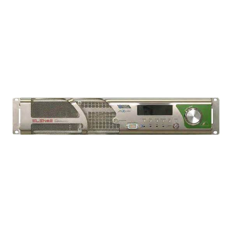
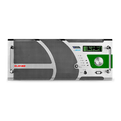
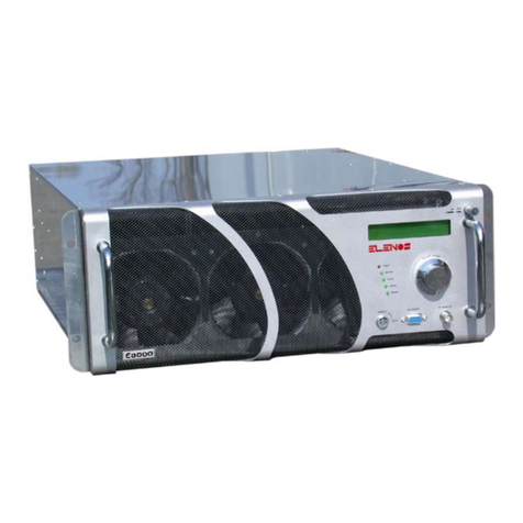
Elenos INDIUM Series User manual

INDIUM SERIES
(the list is in the manual)
SOLID STATE FM TRANSMITTER
USER MANUAL
Rev.01- 22/04/2011
Cod. MAN1001UUK

0470
Operative Office : via G. Amendola 9, 44028 Poggio Renatico (Fe) ITALY
C.C.I.A.A. 101 216
C.Fisc. e P.IVA IT00415540384
For information and assistance please contact the Elenos Technical Assistance Service :
Phone +39 0532 829965
Fax +39 0532 829177
E-mail for general information inf[email protected]
E-mail for support [email protected]om
Or via Website :
www.elenos.com (in On line Support page)
Please, always you give us information about the device serial number (shown on the identifying label).
Elenos s.r.l. declares that the equipment in this documentation complies with 1999/05/CE Directive.
For details see “CE Conformity” Section.
All Copyrights are reserved, you may not reproduce any part of this manual in any form without the express written
permission of Elenos S.r.l.

3
Revision
N° Date Description
00 17/09/2010 First release
01 22/04/2011 Changes of various kind: images, analog output scale values , datasheet,
alarm list.
Revision

4
Family variants
Family variants
Transmitter Number of internal
RF power amplifier
modules
Number of RF driver Maximum output
power
ETG 1600.3 3 (type BLF578) 1 Full power 1600W
ETG 1500.3
ETG 1400.3
ETG 1200.3
ETG 1000.3
ETG 900.3
ETG 800.3
ETG 700.3
ETG 600.3
ETG 500.3
ETG 400.3
ETG 300.3
ETG 250.3
ETG 200.3
ETG 150.3
ETG 100.3
maximum output
power limited to
the nominal value
ETG 1200.2 2 (type BLF578) 1 Full power 1200W
ETG 1000.2
ETG 900.2
ETG 800.2
ETG 700.2
ETG 600.2
ETG 500.2
ETG 400.2
ETG 300.2
ETG 250.2
ETG 200.2
ETG 150.2
ETG 100.2
ETG 80.2
maximum output
power limited to
the nominal value

5Family variants
Transmitter Number of internal
RF power amplifier
modules
Number of RF driver Maximum output
power
ETG 800.1 1 (type BLF578) 0 Full power 800W
ETG 700.1
ETG 600.1
ETG 500.1
ETG 400.1
ETG 300.1
ETG 250.1
ETG 200.1
ETG 150.1
ETG 100.1
ETG 80.1
ETG 50.1
maximum output
power limited to
the nominal value
ETG 150 1 (type MRF) 0 Full power 150W
ETG 100
ETG 80
ETG 50
ETG 40
maximum output
power limited to
the nominal value
ETG 30 0 1 Full power 30W
ETG 20
ETG 10
maximum output
power limited to
the nominal value

6
1 Information note ....................................................................................................................... 9
1.1 Operating Staff ................................................................................................................... 9
1.2 Responsibility .................................................................................................................. 10
1.3 Warranty .......................................................................................................................... 10
1.4 Jurisdicion ........................................................................................................................ 10
2 CE conformity .......................................................................................................................... 11
3 Security .................................................................................................................................... 13
3.1 Precautions ...................................................................................................................... 13
3.2 First aid ............................................................................................................................ 15
3.2.1 Treatment of electrical burns ................................................................................... 15
3.2.1.1 Major burns and cuts ........................................................................................ 15
3.2.1.2 Less severe burns (1st and 2nd degree) .......................................................... 15
3.2.2 Treatment of electric shocks .................................................................................... 15
3.2.2.1 If the casualty has lost consciousness .............................................................. 15
3.2.2.2 If the casualty is conscious ............................................................................... 16
3.3 Station features ............................................................................................................... 16
3.3.1 Environment features ............................................................................................... 16
3.3.2 Wiring features ......................................................................................................... 16
4 General information ................................................................................................................ 19
4.1 Intended use .................................................................................................................... 19
4.2 Shipment .......................................................................................................................... 19
4.3 Unpacking ........................................................................................................................ 19
4.4 Storage ............................................................................................................................. 19
4.5 Off line and disposal ........................................................................................................ 19
4.6 Purchased product verification ........................................................................................ 20
5 Product description ................................................................................................................. 21
5.1 Marks and labels location and type ................................................................................ 21
5.2 Front panel ....................................................................................................................... 22
5.3 Rear Panel ........................................................................................................................ 23
5.4 External connectors description....................................................................................... 24
5.4.1 Interface connector................................................................................................... 24
5.4.2 LEFT/RIGHT connectors ............................................................................................. 25
5.4.3 AES/EBU connector ................................................................................................... 25
5.4.4 AUX connectors ......................................................................................................... 25
5.4.5 MPX connector .......................................................................................................... 25
5.4.6 Monitor/19kHz connector ........................................................................................ 26
5.4.7 TC/TS connector ........................................................................................................ 26
5.4.7.1 Analog output scale value ................................................................................ 27
5.4.8 Profiles connector ..................................................................................................... 28
5.4.9 TCP/IP - Reserved connectors .................................................................................. 29
5.4.10 EIA485 connector .................................................................................................... 29
5.5 Technical brochure ........................................................................................................... 30
5.6 Protections ....................................................................................................................... 31
5.6.1 Software protections ................................................................................................ 31
5.6.1.1 IPF (Intelligent Proportional Foldback) ............................................................. 31
Index
Index

7
5.6.1.2 IPC (Intelligent Power Control) ......................................................................... 31
5.6.1.3 Safety Management (option “Lifextender”) ® ................................................... 31
5.6.2 Hardware protections ............................................................................................... 32
5.7 Options ............................................................................................................................. 33
6 How to active .......................................................................................................................... 35
6.1 Antenna connection ......................................................................................................... 35
6.2 Essential connections to operation .................................................................................. 35
6.3 Mains connection/disconnection .................................................................................... 35
6.4 Factory settings ................................................................................................................ 36
6.5 Main parameters setting ................................................................................................. 37
6.5.1 Frequency setting ..................................................................................................... 37
6.5.2 Power setting ........................................................................................................... 38
6.5.3 Audio level setting ................................................................................................... 39
6.5.4 Audio input setting ................................................................................................... 39
6.5.4.1 MUTE .................................................................................................................. 39
6.5.4.2 MPX ................................................................................................................... 40
6.5.4.3 STEREO ............................................................................................................... 40
6.5.4.4 MONO ................................................................................................................ 41
6.5.4.5 AES/EBU ............................................................................................................ 41
6.5.4.6 AUXILIAR SIGNALS (RDS/SCA)............................................................................ 41
6.6 Turn on ............................................................................................................................. 41
7 Use instructions ....................................................................................................................... 43
7.1 User interface ................................................................................................................... 43
7.1.1 Status and Settings ................................................................................................... 44
7.1.2 Audio Setting ............................................................................................................ 44
7.1.3 Audio levels .............................................................................................................. 44
7.1.4 View and Setting ...................................................................................................... 44
7.1.5 Temperatures ............................................................................................................ 44
7.1.6 Alarms List ................................................................................................................ 45
7.1.7 Events History ........................................................................................................... 45
7.1.8 RF Data ..................................................................................................................... 46
7.1.9 PSUs Data .................................................................................................................. 46
7.1.10 Inputs Level ............................................................................................................ 48
7.1.11 Aux Inputs Level ..................................................................................................... 48
7.1.12 Pilot Level & Phase ................................................................................................. 48
7.1.13 Exciter Clipping ....................................................................................................... 48
7.1.14 Alarms Audio Settings ............................................................................................ 49
7.1.15 AES/EBU Settings .................................................................................................... 49
7.1.16 Time Base ............................................................................................................... 49
7.1.17 Profile Summary 1 of 2 .......................................................................................... 49
7.1.18 Profile Summary 2 of 2 .......................................................................................... 50
7.1.19 Pre Amplifier .......................................................................................................... 52
7.1.20 Voltages .................................................................................................................. 52
7.1.21 System info ............................................................................................................. 52
7.1.22 System Time ........................................................................................................... 52
7.1.23 Clock Pwr Target ..................................................................................................... 53
7.1.24 Max Reflected Power ............................................................................................. 54
7.1.25 COMM. ID LC/RT DISP. MODE ................................................................................... 54
7.1.26 Password Setting .................................................................................................... 54
7.1.27 Password Recovery ................................................................................................. 55
7.1.28 Special Settings ...................................................................................................... 55
7.1.29 Foldback Setting ..................................................................................................... 55
7.1.30 COM1 SPEED SET ...................................................................................................... 56
Index

8
7.1.31 Enable Alarms SMS ................................................................................................. 56
7.1.32 User Alarms Data .................................................................................................... 56
7.1.33 User Alarms Timers ................................................................................................ 56
7.1.34 Uart 0 Info, Uart 1 Info, Uart 2 Info ........................................................................ 57
7.1.35 SMS Enable/-3dB Alarm ......................................................................................... 59
7.1.36 GSM Field/String Id ................................................................................................ 59
7.1.37 Phone N.1 .... Phone N.8 ........................................................................................ 59
7.1.38 SMS Diagnostic ....................................................................................................... 59
7.1.39 Password ................................................................................................................ 60
7.1.40 Exit .......................................................................................................................... 60
7.2 Alarms/events list ........................................................................................................... 61
7.3 SMS list ............................................................................................................................. 63
7.3.1 SMS command (send) .............................................................................................. 63
7.3.2 SMS status/alarm (reception) .................................................................................. 63
7.4 Optional equipment can be connected ........................................................................... 64
7.4.1 PC connection ........................................................................................................... 64
7.4.2 Telemetry connection ............................................................................................... 67
7.4.3 Exchange unit and/or Audio matrix connection ...................................................... 67
7.4.4 Amplifier connection ................................................................................................ 69
8 Maintenance ........................................................................................................................... 71
8.1 Spare parts ....................................................................................................................... 71
8.2 Maintenance (cleaning, replacement, control) ............................................................... 75
8.3 Malfunction (effects, causes and solutions) ................................................................... 76
Index

9
Dear Customer,
thank you for choosing an Elenos product.
Elenos s.r.l. realizes solid state Transmitters for broadcasting radio in the VHF FM ranging
from a minimum power of 10W to a maximum of 30kW, Exchange Unit, Remote Control
Units, etc..
The product is designed to ensure good performance over time, provided periodic
checks and the required simple maintenance are carried out.
The use is very easy and intuitive. Nevertheless it is recommended to carefully read this
manual and its attachments, before performing any operation.
ELENOS s.r.l Management
1.1 Operating Staff
This manual is a part of the product and must be easily found by staff with the task
of installation, operation and maintenance.
Device installation, operation and maintenance must be allowed exclusively to
trained and qualified person, who be aware all risks related to the fact of working
with an equipment connected to dangerous power lines, employing high voltages,
which generates high-power radio frequency.
This manual is not a security rules complete collection, but at the user is required to
know the contents of this document and its annexes.
This product must be used only by holders of Government Grant and is subject to
National Regulations.
1 Information note
Information note

10 Information note
1.2 Responsibility
Elenos is not responsible for damage or injury to objects or to people if caused by
improper procedures or actions conduced by users not sufficiently trained or without
experience.
Descriptions and illustrations contained in this publication are not binding: without
prejudice to the product essential characteristics described, Elenos reserves the right to
make changes to parts, accessories and details that it deems necessary for the improve-
ment of equipment, or for manufacturing or for commercial requirements, at any time,
without warning and without promptly update this publication.
1.3 Warranty
Elenos products are covered by warranty. With the order confirmation or the purchase
you agree to the terms and conditions thereof.
The warranty excludes faults caused by lightning, power supply voltages wrong, negli-
gence, incompetence or abuse by the user, from tampering or repair by unauthorized
people, and uses other than those for which they sold the equipment . The warranty is
excluded for damage by fire, acts of war and unrest.
The warranty does not cover in any case the risk arising from transport.
1.4 Jurisdicion
We inform you that, in case of litigation, the jurisdiction court is the Ferrara Court.

11
Elenos follows, to the marketing of all its products, the Directive 1999/5/CE.
This means:
• Technical fi le, made available, exclusively at the Control Authority, for 10 years after
the last sale on the market of that product type. This fi le contains the product de-
scription, drawings, wiring diagrams, circuits, etc.., standard and technical solutions
list that ensure compliance, test reports, manufacturing process warranty.
• Declaration of Conformity, supplied with the product.
• CE marking is affi xed to the product and to documentation.
• Technical opinion, in writing issued, by an European Notifi ed Body, included in the
Technical Dossier.
• Notifi cation to the member countries where to distribute the product.
Elenos products meet the essential requirements of standard:
a) user or any other person health and safety protection, including the objectives with
respect to safety requirements prescribed by law October 18 1977 n. 791, amended by
Legislative Decree 25 November 1996 n. 626, but without application of voltage limits;
b) the requirements for protection as regards the electromagnetic compatibility, provi-
ded by Legislative Decree 12 November 1996 n. 615;
c) radio equipment in compliance with national frequency allocation, are built to effecti-
vely utilize the radio spectrum allocated to land and spatial and orbital resources, so as
to avoid harmful interference;
d) are also essential requirements those set by the European Commission providing, for
the devices within certain categories or particular types, the requirement of the con-
struction so as to:
• interact via networks with other devices and can be connected to appropriate inter-
faces;
• not harm the network or its operation and do not use wrong network resources,
thereby causing an unacceptable degradation of service;
• contain security features to ensure privacy and personal data protection of user and
subscriber;
• supports certain features ensuring avoidance of fraud;
• supports certain features ensuring access to emergency services;
• supports certain features that facilitate their use by disabled users.
2 CE conformity
CE conformity

12
LIST OF COUNTRIES WHERE THIS APPARATUS CAN BE USED
AT ◊ DE ◊ MT ◊ GB ◊
BE ◊ GR ◊ NL ◊ IS ◊
CY ◊ HU ◊ PL ◊ LI
CZ ◊ IE ◊ PT ◊ NO ◊
DK ◊ IT ◊ SK ◊ CH ◊
EE ◊ LV ◊ SI ◊ BG ◊
FI ◊ LT ◊ ES ◊ RO ◊
FR ◊ LU ◊ SE ◊ TR
AUTHORIZATION IS REQUIRED TO USE THIS EQUIPMENT
CE conformity

13
3 Security
Elenos products meet the safety standards required for this type of equipment.
3.1 Precautions
However, the user must also observe the precautions listed below:
• Original equipment configuration must not be altered. Upon receipt it you must
check that it correspond to the order and in case of non-compliance you must im-
mediately inform Elenos.
• The protective devices should not be disconnected (except to replace), altered, or
changed without permission.
• Check periodically and after the occurrence of a fault the protection devices (such
devices against overvoltage, overcurrent, breaker circuit, etc...)
• For safety and to ensure the device integrity is absolutely forbidden to put it in fun-
ction and/or to handle it with open doors and/or without protection panels and/or
devoid earth connection, which must be always top quality and in accordance with
standards. It is also forbidden to disconnect and/or to modify the means protection
instruments of equipment.
• Before starting work, the equipment must be isolated from the network. Disconnec-
tor must be verified by inspection.
• The equipment should operate only at expected voltage. Incorrect voltage can cause
irreparable damage to the equipment and operator. That statement is on the label
of the product, usually located in the wrapping. This should not be removed for any
reason, even if the equipment was resold.
• The equipment must be powered by an electrical system that is in compliance with
all standards.
• Pictograms are applied on the equipment, indicating safety precautions that must
be carefully respected by anyone who is about to use it. Failure to comply with the
requirements raises the Manufacturer to be liable for any damage to persons or
thing which may arise and makes the operator himself solely responsible.
Dangerous voltage
Security

14 Security
The device is directly connected to the “building installation”
Among the device and “building installation” there is a structure interposed
• To ensure a correct function you must not obstruct the fans. Do not place the unit
near heat sources, near flammable materials, or in closed installations without pro-
per air circulation.
• You must observe the rules relating to fire and security of the station.
• To avoid contamination by liquids. For cleaning to disconnect the power supply. Do
not use liquid or spray cleaners.
• Some components contain TOXIC SUBSTANCES, including BERYLLIUM OXIDE. Be care-
ful because some countries may have rules governing the storage and disposal of
dangerous materials.
• If after an inspection some component is damaged or broken, you must proceed
with caution to any physical contact with hands or otherwise.
• You must ensure that any person who uses a transmitter with dangerous voltage
knows artificial respiration and cardiac massage, and you must train users on first
aid in case of need. In station with electrical equipment you should hang in a visible
position instructions of the phases of assistance to persons involved in an accident
and equip the station of a first-aid kit. It is advisable to have a plan of action for
any operations connected to the emergency, pubblic or private, institutions, that are
readily available to all persons in the room.

15
fig.a
fig.b
Security
3.2 First aid
This paragraph is NOT a complete guide to first aid procedures, but only a summary that
can be used as a reference.
It is the responsibility of all personnel who use this equipment to be ready to admini-
ster adequate first aid and thus prevent avoidable loss of life.
3.2.1 Treatment of electrical burns
3.2.1.1 Major burns and cuts
• Cover the area with a clean cloth.
• Do not burst blisters, remove clothing and any particles of clothing that may be
stuck to the skin. Apply a suitable cream.
• Treat the casualty according to the type of shock.
• Get the casualty to hospital as quickly as possible.
• If arms or legs have been affected, hold them in an elevated position.
WARNING:
If medical assistance is not available within one hour, and the casualty is conscious and
is not trying to vomit, to give them a solution of salt and soda: 1 full teaspoon of salt
and half teaspoon of bicarbonate of soda (sodium bicarbonate) for every 250 ml of
water (neither hot nor cold). To allow the casualty to sip slowly 4 times (1/2 glass) over
a period of 15 minutes.
Stop if the casualty was vomiting. Do not give alcohol.
3.2.1.2 Less severe burns (1st and 2nd degree)
• Apply a cold (not freezing) gauze, using a cloth which is as clean as possible.
• Do not burst blisters, remove clothing and any particles of clothing that are stuck to
the skin. Apply a suitable cream.
• If necessary, give the casualty clean and dry clothing.
• Treat the casualty according to the type of shock.
• Get the casualty to hospital as quickly as possible.
• If arms or legs have been affected, hold them in an elevated position.
3.2.2 Treatment of electric shocks
3.2.2.1 If the casualty has lost consciousness
Lay the casualty on his back on a rigid surface.
A) Air ways (fig. a) :
• if unconscious, open the airways
• push back the forehead
• if necessary open the mouth
• check the breathing
B) Breathing (fig. b) :
• if not breathing, start artificial respiration
• incline the head
• close the nostrils
• apply mouth to the casualty’s mouth
• perform 4 quick respirations
• remember to start breathing again immediately

16
fig.c1
fig.c2
fig.c3
Security
C) Circulation (fig. c1) :
• check the heart beat (fig. c1)
• in the absence of a heart beat, start cardiac massage (fig. c2)
• press the sternum every 1.5 - 2 seconds
• if there is one first aider, perform 15 compressions in about 80 seconds and 2 quick
respirations.
• if there are two first aiders, perform 5 compressions in about 60 seconds and one
respiration (fig. c3)
WARNING :
Do not interrupt the rythm of cardiac compression when the second person is perfor-
ming artificial respiration.
3.2.2.2 If the casualty is conscious
• cover the casualty with a blanket
• ensure the casualty is calm
• loosen clothing and lay the casualty flat
WARNING:
IN ANY CASE CALL A DOCTOR IMMEDIATELY
3.3 Station features
3.3.1 Environment features
To be able to operate freely on the equipment and be able to make installation or
maintenance it is necessary to maintain a minimum distance from the walls on each
side of the machine.
The room must be equipped with an adequate fresh air and filtered from dust, with
adequate capacity with the characteristics of the equipment working in space.
The output exhaust air must be conveyed directly to the outside.
If the size or the duct length are such that assume a significant air flow drop it is neces-
sary to add an extraction device.
At the conveyor exit shall be provided devices against intrusion (compared to insects
or other animals) and precautions should be taken to prevent entry of liquids or other
materials.
The device can operate properly if the temperature is between -5 °C to +45 °C, with
relative humidity to 95%, non-condensing to +40 °C.
3.3.2 Wiring features
The mains system shall be in accordance with all current rules. The power supply should
enable to provide adequate power in accordance with regulations of the installation
country about the service quality of electricity supply.
It’s recommended the use of a network isolating transformer and of an energy reduc-
tion network for high voltage discharges.
Provide a protected switchgear (circuit breaker or fuse) with breaking and flow properly
related to the device absorption characteristics.
Use cables properly sized related to current input.

17Security
The earth connection must be implemented according to current standards. Particular
attention must be used to grounding of the antenna system, because it is exposed to
atmospheric electrical phenomena.
Remember that despite the ground link it is always dangerous to operate on the
apparatus in case of bad weather, with the presence of lightning; in fact, because of
inductance ground connections it is possible, in case of high energy discharge, that the
apparatus reaches dangerous instantaneous levels of voltage.
It is, therefore, appropriate that the equipment is installed in accessible area only to
maintenance people and only for the time necessary to repairs and inspections.

18 Security

19
4 General information
General information
4.1 Intended use
The products described in this document are solid state transmitters with an output
power adjustable from 0W up to the maximum rating (see “Family variants“ section),
using in FM band between 87.5 and 108MHz at 10kHz steps.
The new Indium series, this is his name, stands for new lines, new colors, an innovative
look, and especially new technology, designed to outstanding performance.
The 3 units of equivalent devices in terms of power have been reduced to 2 units, with
obvious advantages in the insertion rack. The final weight is not exceed to 15kg.
The number of internal cables is simplified in order to obtain a reduction of the failure
likelihood and an easier maintenance.
The RF performance, obtained with a number of modules from 3 to 0 depending on the
model purchased, are close to the finish line that is not superable in terms of efficiency,
with devices and technologies of today.
Thanks to these features, ETG series allows a drastic electricity costs reduction.
The product distinguishing features remain : ECOSAVING, ICEFET, VSWR PEAK HOLD, moni-
toring capability, protection against corrosion.
The options would satisfy all needs : MPX, STEREO or AES/EBU versions; TC/TS, TC/
TS+ETHERNET+PROFILES options; LIFEXTENDER.
4.2 Shipment
The shipment may only be performed in its original packaging.
However, although this is designed to avoid product damages, even in mishandling
case, it is recommended to respect the “UP/DOWN” side and to not give shocks.
To make sure that the type of transport and lifting equipment type are capable to sup-
port the weight.
4.3 Unpacking
The staff, handling the product, should operate with gloves and shoes against injury.
Before lifting or handling equipment to verify that you have done to clear the area
of operation, considering a safety area large enough to avoid damage to persons or
objects that may be in the range of maneuver.
4.4 Storage
If you wish, for whatever reason, store the product it is necessary that:
• the temperatures, in the storage, are not exceeded -20 ° - +55 ° C, with humidity
not exceeding 90% at 55 ° C;
• the equipment must be disconnected from the sources of energy;
• the equipment is clean and there are any dust;
• the equipment is covered with a waterproof sheet.
4.5 Off line and disposal
For all aspects concerning the product disposal, reference should be made the specifica-
tions required by European Directives.

20 General information
However, please note that the equipment DOES NOT CONTAIN OILS POLLUTION.
4.6 Purchased product verification
Please note, before installing the equipment, to verify that it has not been damaged
during transportation or storage conditions.
Check that all standard components and accessories ordered have been delivered cor-
rectly, and if not please contact Elenos for material adjustment.
In this case the package must contain at least :
• n°1 Indium series product;
• n°1 “Identification and Quick Start” manual, which should be kept at station, always
attached to the product;
• n°1 “User” manual;
• n°1 CD containing the documentation;
• n°1 cable to PC connection.
Cables, spare parts and other accessories can be obtained by Elenos or Elenos dealers.
This manual suits for next models
49
Table of contents
Other Elenos Transmitter manuals
Popular Transmitter manuals by other brands
Advantech
Advantech WISE-4220 Series user manual

Becker
Becker Centronic EasyControl EC541-II Assembly and operating instructions
ASTEL
ASTEL TTM 101C operating instructions
DPCAV
DPCAV AV681TX Assembly instructions
M-system
M-system W2RS instruction manual
Siemens
Siemens SITRANS TH100Slim Compact operating instructions
Vimar
Vimar LINEA manual

Nautel
Nautel GV20 installation manual

Chiayo
Chiayo SM-6100 IrDA Operation manual
Davis Instruments
Davis Instruments Anemometer Transmitter Kit for Vantage Pro2 installation manual

Visonic
Visonic WT-201 installation instructions

Allstar Products Group
Allstar Products Group MVP CKT-240 installation instructions
