manuals.online logo
Brands
  1. Home
  2. •
  3. Brands
  4. •
  5. Novus
  6. •
  7. Transmitter
  8. •
  9. Novus NP600 User manual

Novus NP600 User manual

NOVUS AUTOMATION. 1/3
NP600
RELATIVE PRESSURE TRANSMITTER – INSTRUCTIONS MANUAL – V1.0x D
PRESENTATION
The NP600 relative pressure transmitter series are robust and
reliable equipment suitable for general industrial applications. Its
great advantage is the possibility of a fast and easy configuration of
the operating range. With the aid of a software, the user has access
to the most important information of the transmitter and can set the
most appropriate configuration for the process.
The NP600 model has a ceramic sensor with high mechanical
stability.
PRECAUTION
Before operating the transmitter, carefully read its specifications and
operating instructions. In case of damage caused by incorrect
operation or inappropriate usage, and its consequences, the
guarantee becomes ineffective and null.
A specialized professional shall perform the installation.
A specific electrical power supply networ should be provided for
instruments use only.
UNPACKING
After unpac ing the product, besides the transmitter it must be
available:
•A quic guide to installation and operation.
•A sealed electrical connector.
•A screw to adjust the transmitter and the connector.
IDENTIFICATION
An identification label is attached to the equipment housing. On this
label, you can found detailed information about the transmitter.
Fig. 1 shows the identification label with their respective information.
Fig. 1 – Transmitter identification
SPECIFICATIONS
Maxim m Range (Max. Range):
0-2 / 0-5 / 0-10 / 0-20 / 0-50 / 0-100 Bar (*)
Rangeability:
3:1
Meas rement Acc racy:
≤ 50 bar ...................................................... < ±0.5 % Max. Range
100 bar ....................................................... < ±1.0 % Max. Range
Including linearity, hysteresis and repeatability, 25 °C
Thermal Maxim m Deviation:
< ±0.06 % Max. Range / °C
Overpress re Range:
Twice the value specified for the Maximum Measurement Range
O tp t Signal (O tp t):
Electric currente, 4-20 mA, 2 wires.
Power S pply (Power):
11 to 33 Vdc
Electrical Connection:
Connector for Type A valves (DIN EN 175301-803), IP65.
Conductor 1.5 mm² (max.) and cables between 6 and 8 mm in
diameter.
Operating temperat re:
-20 to 70 °C
Dinamic Response:
< 30 ms
Process Conection (Thread):
¼ NPT, ½ NPT, ½ BSP, G ¼ (*)
Materials:
Metal housing of the transmitter ...................................... Stainless 316
Sensor (NP600) .................................................. Ceramic (Al
2
O
3
96 %)
Wetted parts (NP600) ............................ Sensor Ceramic (Al
2
O
3
96 %)
.................................................................................. Sealing ring, FKM
................................................... Metal connection, stainless steel 316
Compatibility: Any gas or liquid compatible with the constituent
materials of the wetted parts.
(*)Information available on the product identification label.
NP600 Pressure Transmitter
NOVUS AUTOMATION 2/3
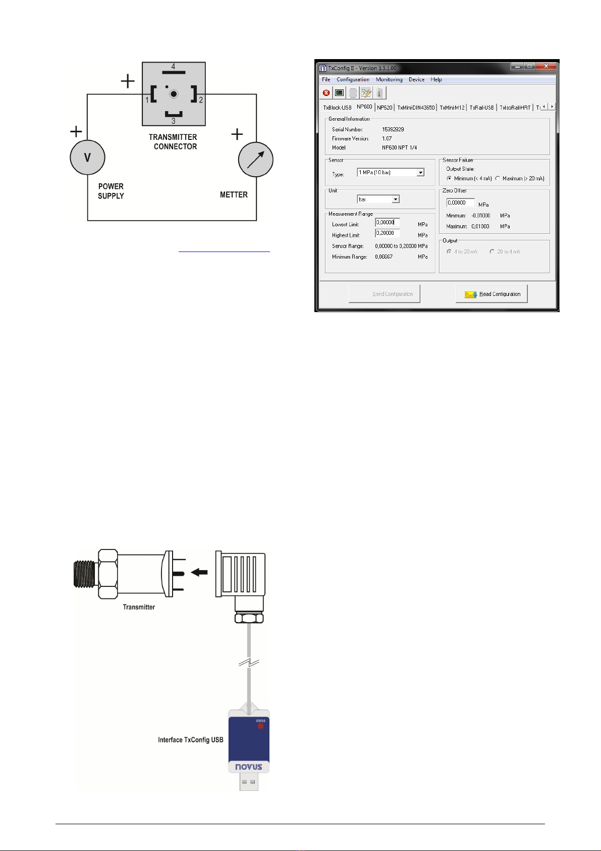
ELECTRICAL CONNECTIONS
Fig. 2 – Electrical Connections
For troubleshooting, visit our FAQ at www.novusautomation.com.
Recommendations for installation
•
Sensor signals conductors must go through the plant system
separate from power leads (loop), if possible in grounded
conduits.
•
The instruments must be powered from the instrumentation power
supply circuit.
•
It is mandatory the use of RC FILTERS (electrical noise
suppressors) in contactor coils, solenoids, etc.
•
To improve the stability, immunity and safety of the measurement,
it is recommended to use the system grounding.
CONFIGURATION
When the transmitter is used with the factory setting, no further
action is required and the transmitter is ready to be installed.
When a new configuration is required, you should use the
Transmitter Configuration Kit. This it includes the TxConfig-II
software, distributed free on the Novus website, and the TxConfig-
USB-DIN43650 interface, which can be purchased in our distribution
and reseller networ .
To install the TxConfig-II software, run the setup file
TxConfigIISetup.exe and follow the instructions of the installer.
The TxConfig interface must be connected to the transmitter
according to Fig. 3. The interface itself provides the electrical power
necessary for transmitter operation during configuration.
Fig. 3 – Connection of the TxConfig-USB
SOFTWARE CONFIGURATION
Fig. 4 – TxConfig II software main screen
When you run the TxConfig-II software, it will recognize
automatically the transmitter and will display the following
information:
1. General Information:
This field shows information that identifying the transmitter. This
information should be sent to the manufacturer in an eventual
request for technical assistance.
2. Unit:
Setting the pressure unit assumed for the measuring range
setting fields.
3. Meas ring Range:
Setting the measurement range assumed by the transmitter.
Lower Limit: target pressure value for 4 mA current.
Upper Limit: target pressure value for 20 mA current.
Minim m Range
Do not set a lower band (span) that the Minim m Range
indicated below in this same field.
4. Sensor Fail re: Sets the current output behaviour when the
transmitter experiences a fault:
Minim m: output current goes to < 4 mA
Maxim m: output current goes to > 20 mA
5. Zero Correction: It corrects small deviations presented in the
transmitter output, when there is no applied pressure.
6. Send Config ration: It applies the new setup. Once sent, the
setup will be immediately adopted by the transmitter.
7. Read Config ration: Reads the current setup in the transmitter
connected. The screen now presents the current setup that may
be changed by the user.
NP600 Pressure Transmitter
NOVUS AUTOMATION 3/3
DIMENSIONS
Fig. 5 – Transmitter dimensions
THREAD
A (mm) B (mm) WEIGHT (g)
NPT ¼ 15.5 46.5 106
NPT ½ 20.0 51.0 159
BSP ½ 14.0 45.0 121
G ¼ 14.0 45.0 121
Table 1 – Dimensions
WARRANTY
Warranty conditions are available on our website
www.novusautomation.com/warranty.

Other Novus Transmitter manuals

Novus TxIsoRail User manual

Novus

Novus TxIsoRail User manual

Novus TXMINI-M12 User manual

Novus

Novus TXMINI-M12 User manual

Novus RHT-WM User manual

Novus

Novus RHT-WM User manual

Novus RHT Climate WM User manual

Novus

Novus RHT Climate WM User manual

Novus TxBlock-USB User manual

Novus

Novus TxBlock-USB User manual

Novus TxIsoRail0-10Vdc User manual

Novus

Novus TxIsoRail0-10Vdc User manual

Novus TxIsoRail User manual

Novus

Novus TxIsoRail User manual

Novus NP785 User manual

Novus

Novus NP785 User manual

Novus TxIsoBlock-HRT User manual

Novus

Novus TxIsoBlock-HRT User manual

Novus TxIsoBlock-HRT User manual

Novus

Novus TxIsoBlock-HRT User manual

Novus TxIsoRail-HRT User manual

Novus

Novus TxIsoRail-HRT User manual

Novus TxIsoRail 0-10 Vdc User manual

Novus

Novus TxIsoRail 0-10 Vdc User manual

Novus RHT-WM-485-LCD User manual

Novus

Novus RHT-WM-485-LCD User manual

Novus TxIsoPack User manual

Novus

Novus TxIsoPack User manual

Novus TxIsoRail-HRT User manual

Novus

Novus TxIsoRail-HRT User manual

Novus TXMINI-M12-485 User manual

Novus

Novus TXMINI-M12-485 User manual

Novus NP640 User manual

Novus

Novus NP640 User manual

Novus TxRail User manual

Novus

Novus TxRail User manual

Novus TxRail User manual

Novus

Novus TxRail User manual

Novus RHT-P10 User manual

Novus

Novus RHT-P10 User manual

Novus TL400-I User manual

Novus

Novus TL400-I User manual

Novus TEMP-WM User manual

Novus

Novus TEMP-WM User manual

Novus NP400 User manual

Novus

Novus NP400 User manual

Novus NVPT-131VTP-HD User manual

Novus

Novus NVPT-131VTP-HD User manual

Popular Transmitter manuals by other brands

Bellman & Symfon BE1520 instruction manual

Bellman & Symfon

Bellman & Symfon BE1520 instruction manual

FISCHER DE46 operating manual

FISCHER

FISCHER DE46 operating manual

Inovonics EN1215WEOL installation instructions

Inovonics

Inovonics EN1215WEOL installation instructions

FISCHER DE45 series Data Sheet and Instruction Manual

FISCHER

FISCHER DE45 series Data Sheet and Instruction Manual

Anywave ATSC 25W quick start guide

Anywave

Anywave ATSC 25W quick start guide

Vega VEGAWELL 52 operating instructions

Vega

Vega VEGAWELL 52 operating instructions

Comtech EF Data FOT3 Product guide

Comtech EF Data

Comtech EF Data FOT3 Product guide

Becker TC445 operating instructions

Becker

Becker TC445 operating instructions

DELTA DORE TTRTC TYXAL+ user guide

DELTA DORE

DELTA DORE TTRTC TYXAL+ user guide

FeinTech ABT00102 instruction manual

FeinTech

FeinTech ABT00102 instruction manual

Vega VEGABAR 80 Series Supplementary instructions

Vega

Vega VEGABAR 80 Series Supplementary instructions

Setra Systems 206 operating instructions

Setra Systems

Setra Systems 206 operating instructions

Firetide HotPort 3203 Hardware installation guide

Firetide

Firetide HotPort 3203 Hardware installation guide

Rose electronics UltraLink E Series Installation and operation manual

Rose electronics

Rose electronics UltraLink E Series Installation and operation manual

Seip SKR2W quick start guide

Seip

Seip SKR2W quick start guide

Furuno LH-3000 Operator's manual

Furuno

Furuno LH-3000 Operator's manual

Uniq UNIQCar manual

Uniq

Uniq UNIQCar manual

Canon WFT-R10 Advanced user's guide

Canon

Canon WFT-R10 Advanced user's guide

manuals.online logo
manuals.online logoBrands
  • About & Mission
  • Contact us
  • Privacy Policy
  • Terms and Conditions

Copyright 2025 Manuals.Online. All Rights Reserved.